EP0919783B1 - Vorrichtung zum Programmieren eines Projektils im Innern eines Waffenrohres - Google Patents
Vorrichtung zum Programmieren eines Projektils im Innern eines Waffenrohres Download PDFInfo
- Publication number
- EP0919783B1 EP0919783B1 EP19980122026 EP98122026A EP0919783B1 EP 0919783 B1 EP0919783 B1 EP 0919783B1 EP 19980122026 EP19980122026 EP 19980122026 EP 98122026 A EP98122026 A EP 98122026A EP 0919783 B1 EP0919783 B1 EP 0919783B1
- Authority
- EP
- European Patent Office
- Prior art keywords
- tube
- programming
- projectile
- reflector
- gun barrel
- Prior art date
- Legal status (The legal status is an assumption and is not a legal conclusion. Google has not performed a legal analysis and makes no representation as to the accuracy of the status listed.)
- Expired - Lifetime
Links
Images

Classifications
-
- F—MECHANICAL ENGINEERING; LIGHTING; HEATING; WEAPONS; BLASTING
- F42—AMMUNITION; BLASTING
- F42C—AMMUNITION FUZES; ARMING OR SAFETY MEANS THEREFOR
- F42C17/00—Fuze-setting apparatus
- F42C17/04—Fuze-setting apparatus for electric fuzes
Definitions
- the technical field of the invention is that of projectile devices, in particular for field artillery or wholesale tank ammunition caliber.
- the current projectiles are more and more often equipped with multi-mode rockets, impact, proximity, chronometric, which are adapted to different targets.
- This type of projectiles it appears necessary, even essential, in order to increase the probabilities of attacks lethal target, to be able to transmit data to them relative to their potential target.
- This data can be the nature and coordinates of the target, the trajectory, but also weather information ...
- patent FR2608267 describes a device allowing the programming of a projectile by optical means.
- This device requires optical emission means and means of monitoring the projectile up to the phase of programming.
- the projectile must also have at its rear part means for receiving light signals. The follow-up of the projectile is binding, because until the programming the weapon system is inoperative and a very good barrier-free intervisibility between the projectile and the tracking means is required.
- the programming of the projectile can be carried out when it is inside the gun barrel, either when it is still stationed, or when of its ballistic phase inside the tube.
- patent EP0023365 proposes a measuring device the speed and / or programming of a projectile to inside a gun barrel.
- the device provides for the installation of an antenna in a bore made in the wall of the barrel of the weapon or in the orifices muzzle brake.
- the antenna which is connected to a source of energy, sends microwave radiation inside of the barrel. These microwave radiation allow the measurement of the initial velocity of the projectile and / or program it.
- This device poses many problems.
- the antenna being placed perpendicular to the axis from the barrel, the radiation from the source energy are diffused in all directions. Indeed, with this device the programming of the projectile is possible as well when this is in the tube the weapon only after its exit, therefore on trajectory. Only one small part of the radiation is therefore directed towards inside the tube towards the ammunition, which generates an unfavorable energy balance, therefore poor reliability of programming in the tube.
- the subject of the invention is a device for programming a projectile inside a weapon barrel comprising a receiver secured to the projectile which is characterized in that it comprises a reflector integral with the weapon barrel and positioned in close proximity to the muzzle of the barrel, the reflector receiving waves sent by a transmitter placed outside the tube the weapon and reflecting them towards the inside of the tube tear.
- the reflector is a mirror.
- the reflector is a reflecting surface integral with a blade of a brake mouth.
- the programming device comprises a transmission line between the transmitter and the reflector can be a coaxial line or a waveguide.
- the frequency of the waves electromagnetic emission is greater than or equal to 2.5 GHz.
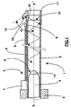
- a weapon for example of large caliber, is conventionally composed of a tube 2 mounted on a cylinder head 3. Ammunition 4 is stationed at inside the tube 2, ready to be drawn.
- the weapon 1 is equipped with a device programming of ammunition 4 composed of a transmitter electromagnetic waves 5 of the microwave type and a wave receiver 6.
- the wave emitter 5 includes a wave generator 7 and a transmission line 9.
- the wave generator 7 is positioned on the outside of the tube 2, so that the transmission line 9 opens substantially near the front end 10 of the tube 2.
- the transmission line 9 here is a coaxial line which is preferably provided an antenna 8 at its front end in order to optimize the directivity of the waves emitted.
- the wave receiver 6 is an antenna housed at the level of a rocket 14 of the ammunition 4. An electronic of received wave processing is also integrated into the ammunition 4.
- a metal reflector 11 is mounted at the end of the tube 2, for example by screwing on the outside of the tube. he has a flat reflecting surface 12 inclined by relation to the axis XX 'of weapon 1 at an angle ⁇ less than 90 ° C, for example of the order of 60 ° C.
- the reflector 11 has at least one radial opening 13 positioned at neighborhood of the reflecting surface 12. The angle ⁇ is chosen so that an incident ray on the surface reflecting is reflected towards the inside of the tube tear.
- Programming or data transmission can also be carried out during the entire course of the projectile down the barrel to the mouth.
- the device for programming a projectile according to the invention therefore does not require any machining which weakens the wall of the barrel.
- Directed reflection of radiation from the surface reflective 12 towards the inside of the barrel allows improve the energy balance penetrating inside the gun barrel.
- Elements sensitive to shooting constraints are distant from the mouth of the tube and could, alternatively, be placed outside of the muzzle, as on the vehicle turret, having a line of slightly longer transmission.
- the reflector 11 could be a mirror fixed in front of the tube and oriented so as to direct the radiation inside the barrel of the weapon.
- the coaxial line can be replaced by a waveguide which would assume the role of transmission line.
- This waveguide would also positioned on the outside of the tube and its front end would be open.
- the waveguide presents several advantages: on the one hand the energy losses during the transmission are less than with a coaxial line, and on the other hand its hardiness gives it a better mechanical protection against external aggressions.
- end of the waveguide on the reflector side, it is possible to add a horn antenna intended to improve the radiation directivity.
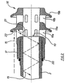
- Figure 2 shows the end of a weapon tube according to a second embodiment of the invention.
- the tube 2 has at its front end a brake mouth 16 secured to the tube by means of a thread 17.
- a nut 20 secures the assembly muzzle brake / tube.
- the muzzle brake 16 has two groups of openings or gills 18a and 18b, here six in number per group.
- the openings 18a, 18b are extended respectively by vanes 19a, 19b which each have a flat surface 21 and a concave surface 22 whose concavity is oriented towards the back of the gun.
- the concavity of the vanes 19a, 19b is adopted, in a known manner, to compensate for the effort exerted by combustion gases.
- the wave transmitter 5 and the receiver 6 described in the first embodiment shown in Figure 1 are included in this second embodiment but are not represented.
- the front end of the line 9 will be placed near an opening 18a muzzle brake 16.
- Concavity 22 of dawn 19a of the muzzle brake is defined so as to ensure the directivity of the radiation towards the interior of the tube tear.
- the muzzle brake 16 is advantageously used as a reflector and the surface concave 22 of dawn 19a as a reflecting surface.
- the angle of inclination or the radius of curvature of the reflective surface will be easily determined by humans of the trade according to the internal diameter of the tube 2 of the weapon, from the distance from the reflective surface to the front end 10 of the tube, as well as the place of reflection of the radiation on the reflecting surface.
- a person skilled in the art will also easily define the bands usable frequencies. These depend on the diameter inner tube, dimensions of the brake opening mouth, surface and surface shape reflective, as well as the type of receiving antenna and the type of transmission lines. The most important criterion binding is the dimension of the brake opening of mouth. Thus, to allow the minimum attenuation of the signal when the wave passes from the outside to inside the tube through the opening 18a of the brake mouth, we will choose an emission wavelength less than or equal to twice the largest dimension of the opening.
- a muzzle brake 16 shown partially and schematically, is secured to the front end of a tube 2 of a weapon.
- the tube 2 is here a smooth tube with internal diameter D equal to 140 mm.
- the muzzle brake 16 has at least one opening 18a of length L and width 1. It also presents, in front of the opening 18a, at least one blade 19 intended to compensate the effort exerted by the combustion gases.
- the blade 19 has an inclined surface 23, of length h in projection on a plane perpendicular to the XX 'axis, forming a truncated cone and a concave surface 22.
- the frustoconical surface 23, which receives a wave 15 emitted by a wave transmitter not shown and which will be described later has a half angle at the top ⁇ substantially equal to 60 ° C.
- the angle ⁇ is the average of two angles ⁇ 1 and ⁇ 2.
- the angle ⁇ 1 corresponds to the minimum angle of inclination of the reflective surface 23 allowing the reflected wave 24 to penetrate into the core of the tube, without leaving through the openings 18a and the angle ⁇ 2 corresponds to the maximum angle allowing the reflected wave 25 penetrating into the core of the tube, without interfere with the front 10 of the tube.
- reflected wave 15 by the surface 23, which is inclined at an angle ⁇ penetrates to inside the barrel of the weapon without interference according to a direction 26, then spreads in the latter until the ammunition.
- the muzzle brake opening 18a has a length L equal to 60 mm which allows the reflected wave to penetrate at inside the tube core without interference.
- the opening is positioned between the blade 19 and the front 10 of the tube 2.
- Sa width 1 is 30 mm.
- a lower emission wavelength or equal to twice the largest dimension of the opening here the length L of 60 mm.
- the length L is the longest dimension of the opening.
- ⁇ the wavelength of the radiation.
- the wave transmitter will preferably be composed of a electromagnetic wave generator, capable of emitting under a frequency substantially equal to 10 GHz, of the klystron type or magnetron and a transmission line which could be a waveguide filled with air.
- the wave receiver housed inside the projectile could be a thin "patch” type antenna.
- the device can be used for weapons of any caliber, in particular for the programming of ammunition of means caliber, even small caliber.
Landscapes
- Engineering & Computer Science (AREA)
- General Engineering & Computer Science (AREA)
- Aiming, Guidance, Guns With A Light Source, Armor, Camouflage, And Targets (AREA)
Claims (7)
- Vorrichtung zur Programmierung eines Projektils (4) im Inneren eines Waffenrohres (2) mit einem fest mit dem Projektil verbundenen Empfänger (6), dadurch gekennzeichnet, dass sie einen Reflektor (11) umfasst, der fest mit dem Waffenrohr verbundenen und in unmittelbarer Nähe der Mündung des Waffenrohrs angeordnet ist, wobei der Reflektor die von einem, außerhalb des Waffenrohrs angeordneten, Sender (5) ausgesandten Wellen (15) empfängt und sie ins Innere des Waffenrohrs reflektiert.
- Programmiervorrichtung nach Anspruch 1, dadurch gekennzeichnet, dass der Reflektor (11) ein Spiegel ist.
- Programmiervorrichtung nach Anspruch 1, dadurch gekennzeichnet, dass der Reflektor (11) eine mit einem Flügel (19) einer Mündungsbremse (16) fest verbundene reflektierende Oberfläche ist.
- Programmiervorrichtung nach irgendeinem der Ansprüche 1 bis 3, dadurch gekennzeichnet, dass sie eine Übertragungsleitung (9) zwischen dem Sender (5) und dem Reflektor (11) umfasst.
- Programmiervorrichtung nach Anspruch 4, dadurch gekennzeichnet, dass die Übertragungsleitung (9) eine Koaxialleitung ist.
- Programmiervorrichtung nach Anspruch 4, dadurch gekennzeichnet, dass die Übertragungsleitung (9) ein Wellenleiter ist.
- Programmiervorrichtung nach irgendeinem der Ansprüche 1 bis 6, dadurch gekennzeichnet, dass die Frequenz der ausgestrahlten elektromagnetischen Wellen höher als oder gleich 2,5 GHz ist.
Applications Claiming Priority (2)
| Application Number | Priority Date | Filing Date | Title |
|---|---|---|---|
| FR9714973 | 1997-11-28 | ||
| FR9714973A FR2771807B1 (fr) | 1997-11-28 | 1997-11-28 | Dispositif de programmation d'un projectile a l'interieur d'un tube d'arme |
Publications (2)
| Publication Number | Publication Date |
|---|---|
| EP0919783A1 EP0919783A1 (de) | 1999-06-02 |
| EP0919783B1 true EP0919783B1 (de) | 2003-02-05 |
Family
ID=9513913
Family Applications (1)
| Application Number | Title | Priority Date | Filing Date |
|---|---|---|---|
| EP19980122026 Expired - Lifetime EP0919783B1 (de) | 1997-11-28 | 1998-11-20 | Vorrichtung zum Programmieren eines Projektils im Innern eines Waffenrohres |
Country Status (3)
| Country | Link |
|---|---|
| EP (1) | EP0919783B1 (de) |
| DE (1) | DE69811187T2 (de) |
| FR (1) | FR2771807B1 (de) |
Cited By (2)
| Publication number | Priority date | Publication date | Assignee | Title |
|---|---|---|---|---|
| US8984999B2 (en) | 2010-02-01 | 2015-03-24 | Rheinmetall Air Defence Ag | Programmable ammunition |
| US20250244096A1 (en) * | 2021-10-21 | 2025-07-31 | AIRSHARE, Inc. | Vibration signaling for a gun |
Families Citing this family (3)
| Publication number | Priority date | Publication date | Assignee | Title |
|---|---|---|---|---|
| DE102005031749A1 (de) * | 2005-07-07 | 2007-01-11 | Rheinmetall Waffe Munition Gmbh | Nicht letales, programmier- und/oder tempierbares Geschoss |
| DE102010006528B4 (de) * | 2010-02-01 | 2013-12-12 | Rheinmetall Air Defence Ag | Verfahren und Vorrichtung zur Programmierung eines Projektils |
| DE102010006529B4 (de) * | 2010-02-01 | 2013-12-12 | Rheinmetall Air Defence Ag | Verfahren und Vorrichtung zur Übertragung von Energie auf ein Projektil |
Family Cites Families (4)
| Publication number | Priority date | Publication date | Assignee | Title |
|---|---|---|---|---|
| US4283989A (en) | 1979-07-31 | 1981-08-18 | Ares, Inc. | Doppler-type projectile velocity measurement and communication apparatus, and method |
| FR2608267B1 (fr) | 1986-12-11 | 1992-12-31 | Seat Bourges Sa | Munition programmable par voie optique et systeme d'arme en comportant application |
| DE3835889A1 (de) * | 1988-08-22 | 1990-03-01 | Rheinmetall Gmbh | Vorrichtung zur zuendereinstellung |
| DE3835678A1 (de) * | 1988-10-20 | 1990-04-26 | Asea Brown Boveri | Rohrwaffensystem |
-
1997
- 1997-11-28 FR FR9714973A patent/FR2771807B1/fr not_active Expired - Fee Related
-
1998
- 1998-11-20 EP EP19980122026 patent/EP0919783B1/de not_active Expired - Lifetime
- 1998-11-20 DE DE1998611187 patent/DE69811187T2/de not_active Expired - Fee Related
Cited By (2)
| Publication number | Priority date | Publication date | Assignee | Title |
|---|---|---|---|---|
| US8984999B2 (en) | 2010-02-01 | 2015-03-24 | Rheinmetall Air Defence Ag | Programmable ammunition |
| US20250244096A1 (en) * | 2021-10-21 | 2025-07-31 | AIRSHARE, Inc. | Vibration signaling for a gun |
Also Published As
| Publication number | Publication date |
|---|---|
| FR2771807A1 (fr) | 1999-06-04 |
| EP0919783A1 (de) | 1999-06-02 |
| DE69811187T2 (de) | 2003-07-24 |
| DE69811187D1 (de) | 2003-03-13 |
| FR2771807B1 (fr) | 1999-12-31 |
Similar Documents
| Publication | Publication Date | Title |
|---|---|---|
| FR2722873A1 (fr) | Systeme de protection d'une cible contre des missiles | |
| EP0273787B1 (de) | Geschoss zum indirekten Angriff auf Panzerfahrzeuge | |
| FR2739921A1 (fr) | Dispositif de protection pour vehicule blinde | |
| FR2526149A1 (fr) | Systeme d'arme et munition de survol | |
| EP0800054B1 (de) | Geschoss dessen Sprengladung durch einen Zielanzeiger ausgelöst wird | |
| EP0646232B1 (de) | Waffensystem für die verteidigung eines gebietes | |
| EP0919783B1 (de) | Vorrichtung zum Programmieren eines Projektils im Innern eines Waffenrohres | |
| FR2518734A1 (fr) | Systeme de defense de zone a effet de saturation | |
| EP0918205B1 (de) | Projektil mit radialer Wirkrichtung | |
| FR2796454A1 (fr) | Arme montee sur un aeronef furtif et pourvue d'un missile, ainsi qu'un systeme d'arme comprenant un aeronef furtif et une telle arme | |
| EP2600097B1 (de) | Kontrollverfahren zur Auslösung eines Gefechtskopfes, Kontrollvorrichtung und Zünder eines Geschosses, in dem ein solches Verfahren zur Anwendung kommt | |
| FR2781043A1 (fr) | Procede et dispositif de brouillage d'une munition guidee en phase finale | |
| EP0388264A1 (de) | Zielmarkierungsvorrichtung zum Anziehen von zielsuchenden Geschossen | |
| FR2771486A1 (fr) | Agencement detecteur pour munition a tete chercheuse | |
| EP0748999B1 (de) | Gefechtskopf, insbesondere mit Hohlladung | |
| EP0624805A1 (de) | Verfahren zur Verbesserung des Richtens einer Waffe mittels Vorläufergranaten und derartige Granate | |
| EP0913662B1 (de) | Hohlladungsprojektil und dazugehöriges Waffensystem | |
| FR2673462A1 (fr) | Projectile anti-blindage. | |
| FR2863055A1 (fr) | Procede de detection de l'approche d'une cible, dispositif de detection et dispositif de protection mettant en oeuvre ce procede | |
| FR2716966A1 (fr) | Système de défense anti-aérienne à très courte portée, de type missile sol-air. | |
| EP4113052B1 (de) | Selbstlenkende vorrichtung für rakete | |
| EP3913317B1 (de) | Unterkalibergeschoss und verfahren zur neutralisierung eines ziels unter verwendung eines solchen geschosses | |
| FR2747185A1 (fr) | Projectile generateur d'eclats dont la charge explosive est declenchee au moyen d'un designateur de cible | |
| CH699028B1 (fr) | Procédé et dispositif de détermination de paramètres de tir. | |
| EP1565703A2 (de) | Verfahren zur flugbahneinrichtung eines drallstabilisierten flugkörpers und ein nach diesem verfahren funktionierenden flugkörper |
Legal Events
| Date | Code | Title | Description |
|---|---|---|---|
| PUAI | Public reference made under article 153(3) epc to a published international application that has entered the european phase |
Free format text: ORIGINAL CODE: 0009012 |
|
| AK | Designated contracting states |
Kind code of ref document: A1 Designated state(s): DE GB SE |
|
| AX | Request for extension of the european patent |
Free format text: AL;LT;LV;MK;RO;SI |
|
| 17P | Request for examination filed |
Effective date: 19991124 |
|
| AKX | Designation fees paid |
Free format text: DE GB SE |
|
| GRAG | Despatch of communication of intention to grant |
Free format text: ORIGINAL CODE: EPIDOS AGRA |
|
| 17Q | First examination report despatched |
Effective date: 20020404 |
|
| GRAG | Despatch of communication of intention to grant |
Free format text: ORIGINAL CODE: EPIDOS AGRA |
|
| GRAH | Despatch of communication of intention to grant a patent |
Free format text: ORIGINAL CODE: EPIDOS IGRA |
|
| GRAH | Despatch of communication of intention to grant a patent |
Free format text: ORIGINAL CODE: EPIDOS IGRA |
|
| GRAA | (expected) grant |
Free format text: ORIGINAL CODE: 0009210 |
|
| AK | Designated contracting states |
Designated state(s): DE GB SE |
|
| REG | Reference to a national code |
Ref country code: GB Ref legal event code: FG4D Free format text: NOT ENGLISH |
|
| GBT | Gb: translation of ep patent filed (gb section 77(6)(a)/1977) |
Effective date: 20030205 |
|
| REF | Corresponds to: |
Ref document number: 69811187 Country of ref document: DE Date of ref document: 20030313 Kind code of ref document: P |
|
| REG | Reference to a national code |
Ref country code: SE Ref legal event code: TRGR |
|
| PLBE | No opposition filed within time limit |
Free format text: ORIGINAL CODE: 0009261 |
|
| STAA | Information on the status of an ep patent application or granted ep patent |
Free format text: STATUS: NO OPPOSITION FILED WITHIN TIME LIMIT |
|
| 26N | No opposition filed |
Effective date: 20031106 |
|
| PGFP | Annual fee paid to national office [announced via postgrant information from national office to epo] |
Ref country code: DE Payment date: 20071113 Year of fee payment: 10 |
|
| PGFP | Annual fee paid to national office [announced via postgrant information from national office to epo] |
Ref country code: SE Payment date: 20071025 Year of fee payment: 10 |
|
| PGFP | Annual fee paid to national office [announced via postgrant information from national office to epo] |
Ref country code: GB Payment date: 20071029 Year of fee payment: 10 |
|
| EUG | Se: european patent has lapsed | ||
| GBPC | Gb: european patent ceased through non-payment of renewal fee |
Effective date: 20081120 |
|
| PG25 | Lapsed in a contracting state [announced via postgrant information from national office to epo] |
Ref country code: DE Free format text: LAPSE BECAUSE OF NON-PAYMENT OF DUE FEES Effective date: 20090603 |
|
| PG25 | Lapsed in a contracting state [announced via postgrant information from national office to epo] |
Ref country code: GB Free format text: LAPSE BECAUSE OF NON-PAYMENT OF DUE FEES Effective date: 20081120 |
|
| PG25 | Lapsed in a contracting state [announced via postgrant information from national office to epo] |
Ref country code: SE Free format text: LAPSE BECAUSE OF NON-PAYMENT OF DUE FEES Effective date: 20081121 |