EP0919824A2 - Bobines RF endocavitaires pour l'imagerie par résonance magnétique - Google Patents
Bobines RF endocavitaires pour l'imagerie par résonance magnétique Download PDFInfo
- Publication number
- EP0919824A2 EP0919824A2 EP98309291A EP98309291A EP0919824A2 EP 0919824 A2 EP0919824 A2 EP 0919824A2 EP 98309291 A EP98309291 A EP 98309291A EP 98309291 A EP98309291 A EP 98309291A EP 0919824 A2 EP0919824 A2 EP 0919824A2
- Authority
- EP
- European Patent Office
- Prior art keywords
- outer cover
- closure
- endocavity
- probe
- coil
- Prior art date
- Legal status (The legal status is an assumption and is not a legal conclusion. Google has not performed a legal analysis and makes no representation as to the accuracy of the status listed.)
- Granted
Links
- 239000000523 sample Substances 0.000 claims abstract description 53
- 239000012530 fluid Substances 0.000 claims description 20
- 238000005202 decontamination Methods 0.000 claims description 18
- 230000003588 decontaminative effect Effects 0.000 claims description 18
- 238000000034 method Methods 0.000 claims description 5
- 230000000249 desinfective effect Effects 0.000 claims description 4
- 239000000463 material Substances 0.000 claims description 4
- 238000009413 insulation Methods 0.000 claims description 3
- 230000000630 rising effect Effects 0.000 claims description 3
- 230000015572 biosynthetic process Effects 0.000 claims description 2
- 238000007789 sealing Methods 0.000 claims description 2
- 238000002595 magnetic resonance imaging Methods 0.000 description 16
- 229920000122 acrylonitrile butadiene styrene Polymers 0.000 description 6
- 210000003679 cervix uteri Anatomy 0.000 description 6
- 238000003384 imaging method Methods 0.000 description 5
- 239000004816 latex Substances 0.000 description 5
- 229920000126 latex Polymers 0.000 description 5
- 210000002307 prostate Anatomy 0.000 description 5
- 210000003484 anatomy Anatomy 0.000 description 4
- 239000000853 adhesive Substances 0.000 description 3
- 230000001070 adhesive effect Effects 0.000 description 3
- 230000004888 barrier function Effects 0.000 description 3
- MHAJPDPJQMAIIY-UHFFFAOYSA-N Hydrogen peroxide Chemical compound OO MHAJPDPJQMAIIY-UHFFFAOYSA-N 0.000 description 2
- 210000000436 anus Anatomy 0.000 description 2
- 238000010276 construction Methods 0.000 description 2
- 230000005284 excitation Effects 0.000 description 2
- 230000001939 inductive effect Effects 0.000 description 2
- 231100000252 nontoxic Toxicity 0.000 description 2
- 230000003000 nontoxic effect Effects 0.000 description 2
- 230000035515 penetration Effects 0.000 description 2
- 229920003023 plastic Polymers 0.000 description 2
- 239000004033 plastic Substances 0.000 description 2
- 239000002904 solvent Substances 0.000 description 2
- 238000004611 spectroscopical analysis Methods 0.000 description 2
- RNFJDJUURJAICM-UHFFFAOYSA-N 2,2,4,4,6,6-hexaphenoxy-1,3,5-triaza-2$l^{5},4$l^{5},6$l^{5}-triphosphacyclohexa-1,3,5-triene Chemical compound N=1P(OC=2C=CC=CC=2)(OC=2C=CC=CC=2)=NP(OC=2C=CC=CC=2)(OC=2C=CC=CC=2)=NP=1(OC=1C=CC=CC=1)OC1=CC=CC=C1 RNFJDJUURJAICM-UHFFFAOYSA-N 0.000 description 1
- LFQSCWFLJHTTHZ-UHFFFAOYSA-N Ethanol Chemical compound CCO LFQSCWFLJHTTHZ-UHFFFAOYSA-N 0.000 description 1
- SXRSQZLOMIGNAQ-UHFFFAOYSA-N Glutaraldehyde Chemical compound O=CCCCC=O SXRSQZLOMIGNAQ-UHFFFAOYSA-N 0.000 description 1
- 238000005481 NMR spectroscopy Methods 0.000 description 1
- 238000004026 adhesive bonding Methods 0.000 description 1
- 230000005540 biological transmission Effects 0.000 description 1
- 239000008280 blood Substances 0.000 description 1
- 210000004369 blood Anatomy 0.000 description 1
- 239000003990 capacitor Substances 0.000 description 1
- 230000008878 coupling Effects 0.000 description 1
- 238000010168 coupling process Methods 0.000 description 1
- 238000005859 coupling reaction Methods 0.000 description 1
- 239000000645 desinfectant Substances 0.000 description 1
- 230000005684 electric field Effects 0.000 description 1
- 239000003063 flame retardant Substances 0.000 description 1
- 230000001976 improved effect Effects 0.000 description 1
- 230000005415 magnetization Effects 0.000 description 1
- 239000012528 membrane Substances 0.000 description 1
- 210000003097 mucus Anatomy 0.000 description 1
- 230000002265 prevention Effects 0.000 description 1
- 210000000664 rectum Anatomy 0.000 description 1
- 230000002040 relaxant effect Effects 0.000 description 1
- 239000000126 substance Substances 0.000 description 1
- 238000003466 welding Methods 0.000 description 1
Images




Classifications
-
- G—PHYSICS
- G01—MEASURING; TESTING
- G01R—MEASURING ELECTRIC VARIABLES; MEASURING MAGNETIC VARIABLES
- G01R33/00—Arrangements or instruments for measuring magnetic variables
- G01R33/20—Arrangements or instruments for measuring magnetic variables involving magnetic resonance
- G01R33/28—Details of apparatus provided for in groups G01R33/44 - G01R33/64
- G01R33/285—Invasive instruments, e.g. catheters or biopsy needles, specially adapted for tracking, guiding or visualization by NMR
Definitions
- the present invention relates to magnetic resonance imaging. It finds particular application in conjunction with medical magnetic resonance imaging systems and will be described with particular reference thereto. It is to be appreciated, however, that the present invention may also find application in conjunction with other types of magnetic resonance imaging systems, magnetic resonance spectroscopy systems, and the like.
- a substantially uniform main magnetic field is generated within an examination region.
- the main magnetic field polarizes the nuclear spin system of a subject being imaged within the examination region.
- Magnetic resonance is excited in dipoles which align with the main magnetic field by transmitting radio frequency excitation signals into the examination region.
- radio frequency pulses transmitted via a radio frequency coil assembly tip the dipoles out of alignment with the main magnetic field and cause a macroscopic magnetic moment vector to precess around an axis parallel to the main magnetic field.
- the precessing magnetic moment in turn, generates a corresponding radio frequency magnetic signal as it relaxes and returns to its former state of alignment with the main magnetic field.
- the radio frequency magnetic resonance signal is received by the radio frequency coil assembly, and from the received signals. an image representation is reconstructed for display on a human viewable display.
- RF receive coils of the intracavitary or endocavitary type are generally used to image these regions as the proximity of the coils in such applications provides improved signal-to-noise ratio over a limited field of view and depth of penetration.
- intracavitary or endocavitary RF receive coils made use of an active RF coil element contained within an inflatable non-permeable balloon.
- An electrical cable interfaced the active RF coil to external electrical circuitry that was used to interface the coil with the magnetic resonance imaging system.
- the device would be inserted into a cavity associated with the region of interest, for example a patients rectum, and the balloon would then be inflated. Finally, the external electrical interface would be used to tune and match the coil to the MRI system.
- endocavitary coils were disposable and would not be reused for multiple scans.
- the active RF coil element was not rigidly formed, and as such, each individual probe had to be tuned and matched.
- Another previous form of an endocavitary probe was reusable for a limited number of times before disposal. This form employed additional latex sheathing which could be disposed of between patient uses. However. the device was reused for only a limited number of times.
- the previous endocavity RF coil probes employed external tuning and matching circuitry as part of the interface with the MRI system.
- the electronic tuning procedures were performed for each individual patient the coil was use on.
- the active RF coil element was not fixed in location within the probe and could not be repeatedly fixed in position relative to the anatomy being imaged, image performance was not repeatable.
- the present invention contemplates an endocavity RF coil assembly for an MRI apparatus which overcomes the above referenced disadvantages.
- an endocavity RF coil assembly for an MRI apparatus.
- the endocavity RF coil assembly includes a reusable probe.
- the reusable probe includes a hollow outer cover having a closed distal end and an open proximate end. The distal end is formed to fit into a cavity of a subject being examined.
- An active RF coil element is rigidly formed about an internal sleeve which is located within the distal end of the outer cover.
- a tuning and matching circuit disposed within the outer cover on the proximate end side of the active RF coil element is arranged on a printed circuit board and attached to the active RF coil element.
- An over-moulded form is connected to the proximate end of the outer cover. The over-moulded form is arranged such that it seals the proximate end of the outer cover closed.
- a main magnetic field control 10 controls superconducting or resistive magnets 12 such that a substantially uniform, temporally constant main magnetic field is created along a z axis through an examination region 14 .
- a magnetic resonance echo means applies a series of radio frequency (RF) and magnetic field gradient pulses to invert or excite magnetic spins, induce magnetic resonance, refocus magnetic resonance, manipulate magnetic resonance, spatially and otherwise encode the magnetic resonance, to saturate spin, and the like to generate magnetic resonance imaging and spectroscopy sequences.
- gradient pulse amplifiers 20 apply current pulses to selected ones or pairs of whole-body gradient coils 22 to create magnetic field gradients along x, y and z-axes of the examination region 14 .
- a digital radio frequency transmitter 24 transmits radio frequency pulses or pulse packets to a whole-body RF coil 26 to transmit RF pulses into the examination region.
- a typical radio frequency pulse is composed of a packet of immediately contiguous pulse segments of short duration which taken together with each other and any applied gradients achieve a selected magnetic resonance manipulation.
- the RF pulses are used to saturate, excite resonance. invert magnetization. refocus resonance. or manipulate resonance in selected portions of the examination region.
- the resonance signals are commonly picked up by the whole-body RF coil 26 .
- a receive-only local radio frequency coil can be used to receive resonance signals introduced by body-coil RF transmissions, such as an endocavitary RF coil assembly probe 30 .
- the resultant radio frequency signals are picked up by the whole-body RF coil 26 or other specialized RF coils and demodulated by a receiver 32 preferably including a preamplifier (not illustrated).
- a sequence control circuit 40 controls the gradient pulse amplifiers 20 and the transmitter 24 to generate any of a plurality of multiple echo sequences such as echo planar imaging, echo volume imaging, gradient and spin echo imaging, fast spin echo imaging, and the like.
- the receiver 32 receives a plurality of data lines in rapid succession following each RF excitation pulse.
- An analog-to-digital converter 42 converts each data line to a digital format.
- the analog-to-digital converter is disposed between the radio frequency receiving coil and the receiver for digital receivers and is disposed downstream from the receiver for analog receivers.
- the radio frequency signals received are demodulated and reconstructed into an image representation by a reconstruction processor 50 which applies a two-dimensional Fourier transform or other appropriate reconstruction algorithm.
- the image may represent a planar slice through the patient. an array of parallel planar slices. a three-dimensional volume, or the like.
- the image is then stored in an image memory 52 where it may be accessed by a display, such as a video monitor 54 which provides a man-readable display of the resultant image.
- an endocavity RF coil assembly is used to pick up radio frequency signals generated by relaxing magnetic dipoles.
- the endocavity RF coil assembly includes a reusable probe 30 which is inserted into a cavity of a subject being examined so as to be contiguous to a region of interest, such as the anus. the prostate, the cervix, or the like.
- the coil's proximity to the region of interest provides for a relatively high signal-to-noise ratio.
- the reusable probe 30 is constructed from a hollow outer cover 60 having a closed distal end 62 and an open proximate end 64 , the closed distal end 62 formed to fit into the cavity of the subject being examined.
- the outer cover 60 is constructed of medical grade ABS plastic.
- the ABS material is appropriately flame retardant and is specifically intended for limited exposure to mucus membrane or blood barrier contact.
- An internal sleeve 70 preferably also made out of medical grade ABS material, is formed to be seated within the hollow outer cover 60 .
- An active RF coil element 72 is positioned within machine grooves along the internal sleeve 70 at the end located within the distal end 62 of the outer cover 60 .
- the end of the internal sleeve which is located within the proximate end 64 of the outer cover 60 holds a tuning and matching circuit which is arranged on a printed circuit board 74 .
- the printed circuit board 74 is attached to the active RF coil element 72 .
- the electronic components mounted on the printed circuit board 74 that make up the tuning and matching circuit are preferably non-magnetic or minimally magnetic.
- the printed circuit board layout for electronic component placement and the distance of the printed circuit board 74 from the active coil element 72 are specifically designed to reduce or eliminate image anomalies caused by the magnetic content of the electronic components used.
- a specially constructed RF cable 80 connects the output of the tuning and matching circuit to the MRI system preamplifier.
- the cable 80 has been constructed from a non-magnetic version of a standard RG174 cable.
- a non-toxic PVC outer jacket Over the outer cable insulation, a non-toxic PVC outer jacket has been moulded.
- the PVC jacket provides an appropriate non-toxic contact with a patient and also provides an electrical field insulating distance between the patient and the outer electrical shield of the cable thereby preventing the risk of RF burn.
- An over-moulded form (closure formation) 90 seals the open proximate end of the hollow outer cover.
- the over-moulded form 90 is constructed of PVC plastic, and can be moulded or fashioned by any appropriate technique.
- the over-moulded form 90 is formed over the outer surface of the proximate end 64 and covers the grooves 66 and flat grooved quadrants 68 .
- the RF cable 80 extends from the tuning and matching circuit out of the open proximate end 64 through the over-moulded form 90 forming a fluid tight seal therewith.
- the over-moulded form 90 As a portion of the over-moulded form 90 is embedded in the circumferential grooves 66 formed on the outer surface of the hollow outer cover 60 , a tight mechanical seal is provided therebetween which is appropriately resistant to the ingress of fluid.
- the interface between the over-moulded form 90 and RF cable 80 is appropriately resistant to the ingress of fluid due to a chemical PVC-to-PVC seal provided therebetween. Further, being that the over-moulded form 90 is formed around the flat grooved quadrants 68 , the over-moulded form 90 will not rotate with respect to the outer cover 60 .
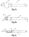
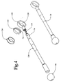
- the endocavity RF coil assembly includes a probe 30 for examination of the prostate.
- the prostate probe includes an internal shell 100 , preferably constructed of medical grade ABS plastic, which has a form for locating and mounting a small printed circuit board (not illustrated) for mounting a resonating capacitor 102 and for locating and mounting the active RF coil element 72 .
- a cover 104 also preferably made out of medical-grade ABS plastic, seals the internal shell 100 providing a barrier between the outside and the components formed on the internal shell 100 .
- a shaft assembly is threaded and joined with a method such as adhesive bonding or solvent bonding to the internal shell 100 .
- the shaft assembly 106 is hollow and connects the internal shell 100 to a printed circuit board outer cover 108 .
- Semi rigid coaxial cables 110 extend through the hollow shaft assembly 106 and connect the active RF coil element 72 to a printed circuit board 74 which resides in the printed circuit board outer cover 108 .
- the printed circuit board 74 holds the tuning and matching circuitry. While not shown, the printed circuit board outer cover 108 includes grooves and flat grooved quadrants, over-moulded form, and specially constructed RF cable in the same manner as the previously discussed preferred embodiment.
- the endocavity RF coil assembly includes a cervical probe 30 .
- the cervical probe 30 includes a hollow annular portion 120 in which the active RF coil element 72 is rigidly secured.
- the active RF coil element 72 is laid out on a flexible printed circuit board 122 .
- the flexible printed circuit board 122 is rigidly secured between an internal ring cover 124 and an external ring-to-shaft assembly 126 .
- Both the internal ring cover 124 and the external ring-to-shaft assembly 126 are preferably constructed of medical grade ABS plastic.
- the external ring-to-shaft assembly 126 is connected to a shaft assembly 128 which houses a printed circuit board 74 containing the tuning and matching circuitry.
- Two 18AWG wires 130 are attached to the printed circuit board and extend therefrom to the active RF coil element through the external ring-to-shaft assembly 126 .
- an insulating sleeve is placed over the two wires.
- the internal ring cover 124 , external ring-to-shaft assembly 126 , and shaft assembly 128 are all appropriately glued to seal the probe 30 from the ingress of fluids.
- this embodiment also employs the specially constructed RF cable and the grooves and flat groove quadrants of the previous embodiments.
- the cervix probe 30 also includes an outer latex cover 132 .
- the outer latex cover 132 is selectively expanded 134 or collapsed 136 to selectively allow the cervix anatomy to reside in a pocket therein such that the anatomy would be located within the ring formed by the annular portion of the probe.
- the latex cover 132 may be expanded and collapsed by inflating and deflating it.
- the endocavity RF coil assembly includes a decontamination vessel 140 for disinfecting the outer cover of the probes.
- the decontamination vessel 140 is compatible with all embodiments of the various probes.
- An upper lip 142 is arranged at the top of the vessel such that it cradles the over-moulded form 90 .
- the upper lip 142 can be constructed to cooperate with the over-moulded form 90 by having the same shape.
- the upper lip 142 holds the probe at a prescribed height so that the outer cover is fully immersed in a decontamination fluid which resides in a reservoir 144 of the decontamination vessel 140 .
- the disinfecting fluid may be glutaraldehyde, alcohol, hydrogen peroxide, or like disinfectant.
- the rectangular throat 146 allows the outer cover of the probes 30 to extend into the disinfecting fluid but will not allow the over-moulded form 90 to pass through.
- a cap 148 is also provided for sealing the decontamination vessel 140 when not in use.
- the decontamination vessel 140 also has an overflow spillway 150 which prevents the decontamination fluid from rising above the prescribed level. That is to say, if the level of the decontamination fluid is too high when the probe 30 is inserted, as the probe 30 displaces the fluid and the level rises, it spills through the overflow spillway 150 rather than rising above the predetermined level.
- an adjustable clamp 160 having jaws 162 adapted to selectively engage the over-moulded form 90 is used to hold the probe 30 in a fixed relationship within the cavity of the subject being examined.
- the adjustable clamp jaws 162 are selectively engaged by turning a backnut 164.
- the jaws are formed to the shape of the over-moulded form 90 to allow maximum freedom in the positioning of the probe 30 .
- the probe does not include a specially constructed RF cable. Rather, the over-moulded form 90 completely seals the open end of the hollow outer cover.
- An electrical component 170 such as an inductive coil, within the over-moulded form 90 is connected to the tuning and matching circuit which is in turn connected to the active RF coil element 72 of the probe 30 .
- the electrical component 170 in the over-moulded form 90 is electronically coupled to electrical components 172 , such as inductive coils, housed within the jaws 162 of the adjustable clamp 160 .
- the electrical components 172 in the jaws 162 of the adjustable clamp 160 are then in turn connected to a preamplifier of the MRI apparatus via cable 172 . In this manner, the probe is connected to the preamplifier of the MRI apparatus without the use of extraneous RF cables.
- the over-moulded form 90 may take on other appropriate shapes.
- the over-moulded form 90 takes the shape of a polyhedron. Each side of the polyhedron is marked with appropriate indicia. In this manner, the over-moulded form 90 can be exploited for indexing the relative orientation of the probe 30 and the active RF coil element 72 rigidly secured therein with respect to the patient.
- the probe 30 may include materials in its construction which emit a limited nuclear magnetic resonance signal. Again, this allows the relative position and orientation of the probe 30 within the subject to be determined relative to the anatomy being imaged.
- One advantageous aspect of the present invention is the fact that the probe 30 is sealed to prevent the ingress of fluids. While described with reference to grooves 66 in which the over-moulded form 90 was embedded to make a mechanical seal, it is appreciated that other means such as ultrasonically welding or use of medical-grade adhesive in construction may be used to create the appropriate seals. As well, seals between any other two interfaces of the probe may be ultrasonically welded, solvent bonded or adhesive bonded with a medical-grade adhesive to create a barrier which prevents the ingress of fluids.
- the preamplifier is integrated into the probe 30 and mounted on the same printed circuit board 74 as the tuning and matching circuit.
- the probes are reusable. Another advantage is that they can be manufactured to meet the electrical and mechanical required compliance standards such as UL 544 and IEC 601. Another advantage is that the active RF coil element location may be fixed with respect to the anatomy being imaged. Another advantage is that external circuitry for performing tuning and matching adjustments on a per-patient basis is eliminated. Another advantage is the reduction of motion artifacts by clamping the probe in a fixed position while performing the scan. Another advantage is the prevention of the ingress of fluids into the interior of the reusable probe. Another advantage is the protection of subjects from RF burn.
Landscapes
- Physics & Mathematics (AREA)
- Health & Medical Sciences (AREA)
- General Health & Medical Sciences (AREA)
- Pathology (AREA)
- Condensed Matter Physics & Semiconductors (AREA)
- General Physics & Mathematics (AREA)
- Magnetic Resonance Imaging Apparatus (AREA)
Applications Claiming Priority (2)
| Application Number | Priority Date | Filing Date | Title |
|---|---|---|---|
| US08/979,053 US6051974A (en) | 1997-11-26 | 1997-11-26 | MRI endocavitary coils and decontamination |
| US979053 | 1997-11-26 |
Publications (3)
| Publication Number | Publication Date |
|---|---|
| EP0919824A2 true EP0919824A2 (fr) | 1999-06-02 |
| EP0919824A3 EP0919824A3 (fr) | 2000-10-25 |
| EP0919824B1 EP0919824B1 (fr) | 2005-12-28 |
Family
ID=25526652
Family Applications (1)
| Application Number | Title | Priority Date | Filing Date |
|---|---|---|---|
| EP98309291A Expired - Lifetime EP0919824B1 (fr) | 1997-11-26 | 1998-11-13 | Bobines RF endocavitaires pour l'imagerie par résonance magnétique |
Country Status (4)
| Country | Link |
|---|---|
| US (1) | US6051974A (fr) |
| EP (1) | EP0919824B1 (fr) |
| JP (1) | JP4307603B2 (fr) |
| DE (1) | DE69832950T2 (fr) |
Cited By (2)
| Publication number | Priority date | Publication date | Assignee | Title |
|---|---|---|---|---|
| WO2002039134A2 (fr) | 2000-11-09 | 2002-05-16 | Koninklijke Philips Electronics N.V. | Bobine d'irm d'endocavite simple a desinfecter |
| DE102007046169A1 (de) * | 2007-09-26 | 2009-04-09 | Schleifring Und Apparatebau Gmbh | Endorektalspule für Kernspintomographen |
Families Citing this family (21)
| Publication number | Priority date | Publication date | Assignee | Title |
|---|---|---|---|---|
| US6263229B1 (en) | 1998-11-13 | 2001-07-17 | Johns Hopkins University School Of Medicine | Miniature magnetic resonance catheter coils and related methods |
| US6549800B1 (en) | 1996-04-25 | 2003-04-15 | Johns Hopkins Unversity School Of Medicine | Methods for in vivo magnetic resonance imaging |
| US7236816B2 (en) * | 1996-04-25 | 2007-06-26 | Johns Hopkins University | Biopsy and sampling needle antennas for magnetic resonance imaging-guided biopsies |
| US6675033B1 (en) | 1999-04-15 | 2004-01-06 | Johns Hopkins University School Of Medicine | Magnetic resonance imaging guidewire probe |
| US6898454B2 (en) | 1996-04-25 | 2005-05-24 | The Johns Hopkins University | Systems and methods for evaluating the urethra and the periurethral tissues |
| WO2000028896A1 (fr) * | 1998-11-18 | 2000-05-25 | Cardiac M.R.I. Inc. | Bobine de reception extensible pour imagerie par resonance magnetique |
| US6356081B1 (en) | 1998-11-25 | 2002-03-12 | Medrad, Inc. | Multimode operation of quadrature phased array MR coil systems |
| US6798206B2 (en) | 1998-11-25 | 2004-09-28 | Medrad, Inc. | Neurovascular coil system and interface and system therefor and method of operating same in a multitude of modes |
| US6344745B1 (en) | 1998-11-25 | 2002-02-05 | Medrad, Inc. | Tapered birdcage resonator for improved homogeneity in MRI |
| US7848788B2 (en) | 1999-04-15 | 2010-12-07 | The Johns Hopkins University | Magnetic resonance imaging probe |
| CA2398967A1 (fr) | 2000-02-01 | 2001-08-09 | Albert C. Lardo | Antenne aiguille transseptale pour irm |
| EP1269206A2 (fr) | 2000-03-24 | 2003-01-02 | Surgi-Vision | Dispositif, systemes et procedes d'imagerie par resonance magnetique in vivo |
| US6832108B2 (en) | 2001-04-19 | 2004-12-14 | Koninklijke Philips Electronics, N.V. | Endovaginal MRI receiver coil |
| US7084629B2 (en) | 2002-11-27 | 2006-08-01 | Medrad, Inc. | Parallel imaging compatible birdcage resonator |
| US20040158144A1 (en) * | 2003-02-03 | 2004-08-12 | Topshooter Medical Imri Inc. | NMR probe particularly useful for intra-luminal imaging |
| US20080129295A1 (en) * | 2005-03-10 | 2008-06-05 | Koninklijke Philips Electronics N.V. | Seamless Enclosures for Mr Rf Coils |
| US7945308B2 (en) * | 2005-12-27 | 2011-05-17 | General Electric Company | Systems, methods and apparatus for an endo-rectal receive-only probe |
| US9913596B2 (en) | 2010-11-25 | 2018-03-13 | Invivo Corporation | Systems and methods for MRI guided trans-orifice and transperineal intervention apparatus with adjustable biopsy needle insertion |
| CN105228520B (zh) * | 2011-12-15 | 2019-03-01 | 艾姆瑞科医疗系统有限公司 | Mr主动跟踪系统 |
| BR112014030216A2 (pt) | 2012-06-07 | 2017-06-27 | Koninklijke Philips Nv | bobina de radiofrequência local de ressonância magnética; sistema de ressonância magnética; método para obtenção de imagem de uma região com a ressonância magnética; meio não transitório legível em computador; e sistema |
| EP2967423B1 (fr) | 2013-03-15 | 2021-06-30 | Synaptive Medical Inc. | Dispositifs d'imagerie insérables pour procédures chirurgicales |
Family Cites Families (6)
| Publication number | Priority date | Publication date | Assignee | Title |
|---|---|---|---|---|
| US5050607A (en) * | 1987-03-04 | 1991-09-24 | Huntington Medical Research Institutes | High resolution magnetic resonance imaging of body cavities |
| US5348010A (en) * | 1989-02-24 | 1994-09-20 | Medrea, Inc., Pennsylvania Corp., Pa. | Intracavity probe and interface device for MRI imaging and spectroscopy |
| CA2010899A1 (fr) * | 1989-02-27 | 1990-08-27 | George J. Misic | Sonde intracavitaire et dispositif d'interface utilises en irm et en spectroscopie |
| CA2079974C (fr) * | 1991-10-07 | 1996-07-23 | Edward J. Rhinehart | Sonde d'imagerie et de spectroscopie a resonance magnetique, particulierement pour la region cervicale |
| JPH07303625A (ja) * | 1994-03-18 | 1995-11-21 | Olympus Optical Co Ltd | 磁気共鳴断層撮影装置用器具 |
| JPH09103415A (ja) * | 1995-10-11 | 1997-04-22 | Olympus Optical Co Ltd | 磁気共鳴観測装置 |
-
1997
- 1997-11-26 US US08/979,053 patent/US6051974A/en not_active Expired - Fee Related
-
1998
- 1998-11-13 DE DE69832950T patent/DE69832950T2/de not_active Expired - Lifetime
- 1998-11-13 EP EP98309291A patent/EP0919824B1/fr not_active Expired - Lifetime
- 1998-11-26 JP JP33557798A patent/JP4307603B2/ja not_active Expired - Fee Related
Cited By (4)
| Publication number | Priority date | Publication date | Assignee | Title |
|---|---|---|---|---|
| WO2002039134A2 (fr) | 2000-11-09 | 2002-05-16 | Koninklijke Philips Electronics N.V. | Bobine d'irm d'endocavite simple a desinfecter |
| WO2002039134A3 (fr) * | 2000-11-09 | 2002-08-01 | Marconi Medical Sys Inc | Bobine d'irm d'endocavite simple a desinfecter |
| US6501980B1 (en) | 2000-11-09 | 2002-12-31 | Koninklijke Philips Electronics N.V. | Easily decontaminated MRI endocavity coils |
| DE102007046169A1 (de) * | 2007-09-26 | 2009-04-09 | Schleifring Und Apparatebau Gmbh | Endorektalspule für Kernspintomographen |
Also Published As
| Publication number | Publication date |
|---|---|
| EP0919824B1 (fr) | 2005-12-28 |
| DE69832950D1 (de) | 2006-02-02 |
| US6051974A (en) | 2000-04-18 |
| JPH11233333A (ja) | 1999-08-27 |
| EP0919824A3 (fr) | 2000-10-25 |
| DE69832950T2 (de) | 2006-08-24 |
| JP4307603B2 (ja) | 2009-08-05 |
Similar Documents
| Publication | Publication Date | Title |
|---|---|---|
| US6051974A (en) | MRI endocavitary coils and decontamination | |
| JP3854667B2 (ja) | 磁気共鳴システム及び磁気共鳴作像兼追跡システム | |
| JP2955484B2 (ja) | 医療器具を追跡する磁気共鳴画像装置 | |
| US4932411A (en) | Intervivo coil for a nuclear magnetic resonance tomographic apparatus | |
| US5271400A (en) | Tracking system to monitor the position and orientation of a device using magnetic resonance detection of a sample contained within the device | |
| JP3983666B2 (ja) | 容易に除染されるmri腔内コイル | |
| EP0754954B1 (fr) | Procédé et appareil de résonance magnétique | |
| US6975896B2 (en) | Fiducial markers for MRI | |
| EP0864102B1 (fr) | Dispositif effractif destine a etre utilise dans un appareil d'imagerie a resonance magnetique | |
| EP0604587B1 (fr) | Sonde colique pour imagerie par resonance magnetique et spectroscopie | |
| US5318025A (en) | Tracking system to monitor the position and orientation of a device using multiplexed magnetic resonance detection | |
| US6317091B1 (en) | Apparatus for inductively coupling a nuclear magnetic resonance signal into a reception antenna, and medical instrument incorporating such an apparatus | |
| WO1999027390A1 (fr) | Imagerie par resonance magnetique employant des coordonnees cylindriques et une antenne de catheter | |
| US6832108B2 (en) | Endovaginal MRI receiver coil | |
| US7031763B1 (en) | MRI shoulder coil | |
| US20090082664A1 (en) | Endorectal Coil for Magnetic Resonance Tomograph | |
| USRE40587E1 (en) | Antenna for magnetic resonance imaging and method of use | |
| JPH10179553A (ja) | 核磁気共鳴像形成装置 | |
| EP0922965B1 (fr) | Arrangement de bobines r.f.pour la résonance magnétique | |
| JPH10277009A (ja) | 磁気共鳴検査装置において被検体内に挿入した挿入器具の位置を監視する装置および方法 | |
| WO2003102616A1 (fr) | Recipient jetable a utiliser avec un systeme d'imagerie par resonance magnetique ouvert | |
| CN222028404U (zh) | 线圈固定装置以及磁共振成像设备 | |
| US20050043613A1 (en) | System and method to reduce artifacts and improve coverage in mr spectroscopy | |
| JP3244376B2 (ja) | 磁気共鳴観測装置 | |
| JPS6343650A (ja) | 磁気共鳴装置 |
Legal Events
| Date | Code | Title | Description |
|---|---|---|---|
| PUAI | Public reference made under article 153(3) epc to a published international application that has entered the european phase |
Free format text: ORIGINAL CODE: 0009012 |
|
| AK | Designated contracting states |
Kind code of ref document: A2 Designated state(s): DE FR NL |
|
| AX | Request for extension of the european patent |
Free format text: AL;LT;LV;MK;RO;SI |
|
| RIN1 | Information on inventor provided before grant (corrected) |
Inventor name: BRAUM, WILLIAM O. Inventor name: STERN, BENJAMIN R. Inventor name: CARLON, JOHN T. Inventor name: MOLYNEAUX, DAVID A. Inventor name: REISKER, THEODORE, J. |
|
| PUAL | Search report despatched |
Free format text: ORIGINAL CODE: 0009013 |
|
| AK | Designated contracting states |
Kind code of ref document: A3 Designated state(s): AT BE CH CY DE DK ES FI FR GB GR IE IT LI LU MC NL PT SE |
|
| AX | Request for extension of the european patent |
Free format text: AL;LT;LV;MK;RO;SI |
|
| RAP1 | Party data changed (applicant data changed or rights of an application transferred) |
Owner name: MARCONI MEDICAL SYSTEMS, INC. |
|
| 17P | Request for examination filed |
Effective date: 20010418 |
|
| AKX | Designation fees paid |
Free format text: DE FR NL |
|
| RAP1 | Party data changed (applicant data changed or rights of an application transferred) |
Owner name: PHILIPS MEDICAL SYSTEMS (CLEVELAND), INC. |
|
| RAP1 | Party data changed (applicant data changed or rights of an application transferred) |
Owner name: KONINKLIJKE PHILIPS ELECTRONICS N.V. |
|
| 17Q | First examination report despatched |
Effective date: 20041011 |
|
| GRAP | Despatch of communication of intention to grant a patent |
Free format text: ORIGINAL CODE: EPIDOSNIGR1 |
|
| GRAS | Grant fee paid |
Free format text: ORIGINAL CODE: EPIDOSNIGR3 |
|
| GRAA | (expected) grant |
Free format text: ORIGINAL CODE: 0009210 |
|
| AK | Designated contracting states |
Kind code of ref document: B1 Designated state(s): DE FR NL |
|
| PG25 | Lapsed in a contracting state [announced via postgrant information from national office to epo] |
Ref country code: NL Free format text: LAPSE BECAUSE OF FAILURE TO SUBMIT A TRANSLATION OF THE DESCRIPTION OR TO PAY THE FEE WITHIN THE PRESCRIBED TIME-LIMIT Effective date: 20051228 |
|
| REF | Corresponds to: |
Ref document number: 69832950 Country of ref document: DE Date of ref document: 20060202 Kind code of ref document: P |
|
| NLV1 | Nl: lapsed or annulled due to failure to fulfill the requirements of art. 29p and 29m of the patents act | ||
| ET | Fr: translation filed | ||
| PLBE | No opposition filed within time limit |
Free format text: ORIGINAL CODE: 0009261 |
|
| STAA | Information on the status of an ep patent application or granted ep patent |
Free format text: STATUS: NO OPPOSITION FILED WITHIN TIME LIMIT |
|
| 26N | No opposition filed |
Effective date: 20060929 |
|
| PGFP | Annual fee paid to national office [announced via postgrant information from national office to epo] |
Ref country code: FR Payment date: 20111214 Year of fee payment: 14 |
|
| PGFP | Annual fee paid to national office [announced via postgrant information from national office to epo] |
Ref country code: DE Payment date: 20120131 Year of fee payment: 14 |
|
| REG | Reference to a national code |
Ref country code: FR Ref legal event code: ST Effective date: 20130731 |
|
| REG | Reference to a national code |
Ref country code: DE Ref legal event code: R119 Ref document number: 69832950 Country of ref document: DE Effective date: 20130601 |
|
| PG25 | Lapsed in a contracting state [announced via postgrant information from national office to epo] |
Ref country code: DE Free format text: LAPSE BECAUSE OF NON-PAYMENT OF DUE FEES Effective date: 20130601 |
|
| PG25 | Lapsed in a contracting state [announced via postgrant information from national office to epo] |
Ref country code: FR Free format text: LAPSE BECAUSE OF NON-PAYMENT OF DUE FEES Effective date: 20121130 |