EP0919893A2 - Machine d'usinage avec appareil à commande numérique - Google Patents
Machine d'usinage avec appareil à commande numérique Download PDFInfo
- Publication number
- EP0919893A2 EP0919893A2 EP98309800A EP98309800A EP0919893A2 EP 0919893 A2 EP0919893 A2 EP 0919893A2 EP 98309800 A EP98309800 A EP 98309800A EP 98309800 A EP98309800 A EP 98309800A EP 0919893 A2 EP0919893 A2 EP 0919893A2
- Authority
- EP
- European Patent Office
- Prior art keywords
- axis
- predetermined
- cutting blade
- workpiece
- data
- Prior art date
- Legal status (The legal status is an assumption and is not a legal conclusion. Google has not performed a legal analysis and makes no representation as to the accuracy of the status listed.)
- Withdrawn
Links
Images


Classifications
-
- B—PERFORMING OPERATIONS; TRANSPORTING
- B23—MACHINE TOOLS; METAL-WORKING NOT OTHERWISE PROVIDED FOR
- B23C—MILLING
- B23C3/00—Milling particular work; Special milling operations; Machines therefor
- B23C3/16—Working surfaces curved in two directions
-
- B—PERFORMING OPERATIONS; TRANSPORTING
- B27—WORKING OR PRESERVING WOOD OR SIMILAR MATERIAL; NAILING OR STAPLING MACHINES IN GENERAL
- B27C—PLANING, DRILLING, MILLING, TURNING OR UNIVERSAL MACHINES FOR WOOD OR SIMILAR MATERIAL
- B27C5/00—Machines designed for producing special profiles or shaped work, e.g. by rotary cutters; Equipment therefor
-
- B—PERFORMING OPERATIONS; TRANSPORTING
- B27—WORKING OR PRESERVING WOOD OR SIMILAR MATERIAL; NAILING OR STAPLING MACHINES IN GENERAL
- B27M—WORKING OF WOOD NOT PROVIDED FOR IN SUBCLASSES B27B - B27L; MANUFACTURE OF SPECIFIC WOODEN ARTICLES
- B27M3/00—Manufacture or reconditioning of specific semi-finished or finished articles
- B27M3/20—Manufacture or reconditioning of specific semi-finished or finished articles of lasts; of shoes, e.g. sabots; of parts of shoes, e.g. heels
-
- G—PHYSICS
- G05—CONTROLLING; REGULATING
- G05B—CONTROL OR REGULATING SYSTEMS IN GENERAL; FUNCTIONAL ELEMENTS OF SUCH SYSTEMS; MONITORING OR TESTING ARRANGEMENTS FOR SUCH SYSTEMS OR ELEMENTS
- G05B19/00—Program-control systems
- G05B19/02—Program-control systems electric
- G05B19/18—Numerical control [NC], i.e. automatically operating machines, in particular machine tools, e.g. in a manufacturing environment, so as to execute positioning, movement or co-ordinated operations by means of program data in numerical form
- G05B19/4097—Numerical control [NC], i.e. automatically operating machines, in particular machine tools, e.g. in a manufacturing environment, so as to execute positioning, movement or co-ordinated operations by means of program data in numerical form characterised by using design data to control NC machines, e.g. CAD/CAM
- G05B19/4099—Surface or curve machining, making three-dimensional [3D] objects, e.g. desktop manufacturing
-
- G—PHYSICS
- G05—CONTROLLING; REGULATING
- G05B—CONTROL OR REGULATING SYSTEMS IN GENERAL; FUNCTIONAL ELEMENTS OF SUCH SYSTEMS; MONITORING OR TESTING ARRANGEMENTS FOR SUCH SYSTEMS OR ELEMENTS
- G05B2219/00—Program-control systems
- G05B2219/30—Nc systems
- G05B2219/33—Director till display
- G05B2219/33263—Conversion, transformation of coordinates, cartesian or polar
-
- G—PHYSICS
- G05—CONTROLLING; REGULATING
- G05B—CONTROL OR REGULATING SYSTEMS IN GENERAL; FUNCTIONAL ELEMENTS OF SUCH SYSTEMS; MONITORING OR TESTING ARRANGEMENTS FOR SUCH SYSTEMS OR ELEMENTS
- G05B2219/00—Program-control systems
- G05B2219/30—Nc systems
- G05B2219/34—Director, elements to supervisory
- G05B2219/34103—Taking planar slices from a 3-D shape
-
- G—PHYSICS
- G05—CONTROLLING; REGULATING
- G05B—CONTROL OR REGULATING SYSTEMS IN GENERAL; FUNCTIONAL ELEMENTS OF SUCH SYSTEMS; MONITORING OR TESTING ARRANGEMENTS FOR SUCH SYSTEMS OR ELEMENTS
- G05B2219/00—Program-control systems
- G05B2219/30—Nc systems
- G05B2219/37—Measurements
- G05B2219/37573—In-cycle, insitu, during machining workpiece is measured continuously
-
- G—PHYSICS
- G05—CONTROLLING; REGULATING
- G05B—CONTROL OR REGULATING SYSTEMS IN GENERAL; FUNCTIONAL ELEMENTS OF SUCH SYSTEMS; MONITORING OR TESTING ARRANGEMENTS FOR SUCH SYSTEMS OR ELEMENTS
- G05B2219/00—Program-control systems
- G05B2219/30—Nc systems
- G05B2219/45—Nc applications
- G05B2219/45243—Shoe, footwear making
-
- Y—GENERAL TAGGING OF NEW TECHNOLOGICAL DEVELOPMENTS; GENERAL TAGGING OF CROSS-SECTIONAL TECHNOLOGIES SPANNING OVER SEVERAL SECTIONS OF THE IPC; TECHNICAL SUBJECTS COVERED BY FORMER USPC CROSS-REFERENCE ART COLLECTIONS [XRACs] AND DIGESTS
- Y10—TECHNICAL SUBJECTS COVERED BY FORMER USPC
- Y10T—TECHNICAL SUBJECTS COVERED BY FORMER US CLASSIFICATION
- Y10T29/00—Metal working
- Y10T29/51—Plural diverse manufacturing apparatus including means for metal shaping or assembling
- Y10T29/5104—Type of machine
- Y10T29/5109—Lathe
- Y10T29/5114—Lathe and tool
-
- Y—GENERAL TAGGING OF NEW TECHNOLOGICAL DEVELOPMENTS; GENERAL TAGGING OF CROSS-SECTIONAL TECHNOLOGIES SPANNING OVER SEVERAL SECTIONS OF THE IPC; TECHNICAL SUBJECTS COVERED BY FORMER USPC CROSS-REFERENCE ART COLLECTIONS [XRACs] AND DIGESTS
- Y10—TECHNICAL SUBJECTS COVERED BY FORMER USPC
- Y10T—TECHNICAL SUBJECTS COVERED BY FORMER US CLASSIFICATION
- Y10T409/00—Gear cutting, milling, or planing
- Y10T409/30—Milling
- Y10T409/30084—Milling with regulation of operation by templet, card, or other replaceable information supply
- Y10T409/300896—Milling with regulation of operation by templet, card, or other replaceable information supply with sensing of numerical information and regulation without mechanical connection between sensing means and regulated means [i.e., numerical control]
-
- Y—GENERAL TAGGING OF NEW TECHNOLOGICAL DEVELOPMENTS; GENERAL TAGGING OF CROSS-SECTIONAL TECHNOLOGIES SPANNING OVER SEVERAL SECTIONS OF THE IPC; TECHNICAL SUBJECTS COVERED BY FORMER USPC CROSS-REFERENCE ART COLLECTIONS [XRACs] AND DIGESTS
- Y10—TECHNICAL SUBJECTS COVERED BY FORMER USPC
- Y10T—TECHNICAL SUBJECTS COVERED BY FORMER US CLASSIFICATION
- Y10T409/00—Gear cutting, milling, or planing
- Y10T409/30—Milling
- Y10T409/304536—Milling including means to infeed work to cutter
- Y10T409/305544—Milling including means to infeed work to cutter with work holder
- Y10T409/305656—Milling including means to infeed work to cutter with work holder including means to support work for rotation during operation
- Y10T409/305712—Milling including means to infeed work to cutter with work holder including means to support work for rotation during operation and including means to infeed cutter toward work axis
-
- Y—GENERAL TAGGING OF NEW TECHNOLOGICAL DEVELOPMENTS; GENERAL TAGGING OF CROSS-SECTIONAL TECHNOLOGIES SPANNING OVER SEVERAL SECTIONS OF THE IPC; TECHNICAL SUBJECTS COVERED BY FORMER USPC CROSS-REFERENCE ART COLLECTIONS [XRACs] AND DIGESTS
- Y10—TECHNICAL SUBJECTS COVERED BY FORMER USPC
- Y10T—TECHNICAL SUBJECTS COVERED BY FORMER US CLASSIFICATION
- Y10T409/00—Gear cutting, milling, or planing
- Y10T409/30—Milling
- Y10T409/306664—Milling including means to infeed rotary cutter toward work
- Y10T409/30756—Machining arcuate surface
Definitions
- the present invention relates to a processing machine with a numerical control apparatus for processing a workpiece into a predetermined solid or three-dimensional shape, e.g. a last for a shoe having a predetermined shape. Also, this invention relates to a computing apparatus for preparing cutter blade movement data in accordance with which a cutter blade of the processing machine is moved.
- a processing machine with a numerical control apparatus comprises a rotary cutter blade adapted to rotate about an axis.
- the processing machine includes memory means for storing therein cutter blade movement data in accordance with which the cutter blade is to be moved relative to a workpiece rotating about a predetermined axis to thereby process the workpiece into a three-dimensional object having a predetermined three-dimensional shape.
- the processing machine further comprises moving means for causing relative movement of the cutter blade in accordance with the cutter blade movement data.
- the predetermined three-dimensional shape comprises a number of cross-sections in planes perpendicular to the predetermined axis. At least one of the cross-sections is non-circular, has a different shape or size from at least one of the remaining cross-sections or is rotated about the predetermined axis relative to at least one of the remaining cross-sections.
- the cutter blade movement data referred to herein is data which provides such relative movement of the rotary cutter blade that if the finally resulting object having the predetermined three-dimensional shape (hereinafter sometimes referred to as predetermined three-dimensional object) were rotated about the predetermined axis, the surface of the body of revolution of the rotary cutter blade would contact the surface of the object at respective rotational positions of the three-dimensional object.
- the cutter blade movement data may be prepared in the following manner. Let it be assumed that the three-dimensional object is rotated by an increment of a given angle about the said predetermined axis.
- the cutter blade movement data is prepared from data representing respective points on the contour lines of respective ones of the cross-sections of the three-dimensional object at its respective rotational positions, and data representing respective points on the locus drawn by the cutting edge of the rotating cutter blade.
- the cutter blade movement data may be prepared in the following manner. Let it be assumed that the three-dimensional object is placed in a three dimensional coordinate system with its Z-axis being in alignment with the predetermined axis about which the three-dimensional object is rotated.
- the movement data is prepared from data obtained by rotating about the Z-axis data of the X, Y and Z coordinates of respective ones of various points on the contour line of each cross-section of the three-dimensional object by a predetermined incremental angle, and from data of the X, Y and Z coordinates of respective ones of points on the locus of the rotation of the rotary cutter blade.
- the cutter blade movement data may be data in accordance with which, at each of the rotational positions of the three-dimensional object rotated by the predetermined incremental angle, the cutting edge of the cutter blade is positioned at a location corresponding to the maximum one of the X coordinates of points on a part of the contour line of each cross-section spanning over a predetermined angular range including the X-Z plane.
- the cutter blade may have a center axis extending at a predetermined angle with respect to the Z-axis, and have a cutting edge in the shape of a semi-circle having a diameter extending in parallel with the center axis.
- the cutter blade movement data may be data in accordance with which, at each of the rotational positions of the object, spaced from each other by the predetermined incremental angle, the cutting edge of the cutter blade is positioned at a location where it contacts the maximum one of the X coordinates of points on contour lines of a plurality of cross-sections within a predetermined range along the Z-axis.
- the points are the ones on parts of the contour lines spanning over a predetermined angular range of the contour lines.
- the computation system computes cutter blade movement data for moving a rotary cutter blade of a processing machine with a numerical control apparatus.
- the rotary cutter blade rotates about an axis.
- the processing machine further includes memory means for storing therein the cutter blade movement data as computed by the computation system, in accordance with which the cutter blade is to be moved relative to a workpiece rotating about a predetermined axis to thereby process the workpiece into a three-dimensional object having a predetermined three-dimensional shape.
- the processing machine further comprises moving means for causing relative movement of the cutter blade in accordance with the cutter blade movement data.
- the three-dimensional object may be a body having a plurality of cross-sections perpendicular to the predetermined axis. At least one of the cross-sections is non-circular, has a different shape or size from at least one of the remaining cross-sections or rotated about the predetermined axis relative to at least one of the remaining cross-sections.
- the cutter blade movement data referred to herein is data to provide such relative movement of the rotary cutter blade that if the ultimately resulting object having the predetermined three-dimensional shape were rotated about the predetermined axis, the surface of the body o revolution of the rotary cutter blade would contact the surface of the three-dimensional object at its respective rotational positions.
- the computation system may be used to prepare cutter blade movement data in accordance with which a cutting edge of a rotary cutter blade is to be moved to cut the workpiece into a last for a shoe, and may include computation means for computing data of coordinates of each of respective points on the locus of the cutting edge of the cutter blade in accordance with the following equations.
- the workpiece is placed in a three-dimensional coordinate system with its Z-axis being in alignment with the predetermined axis about which the workpiece is rotated, and that the cutter blade has a semi-circular cutting edge.
- R is the radius of the body of revolution of the cutting blade
- r is the radius of the semi-circle of the cutting edge
- t is a parameter representing an angle between the radius of the semi-circle passing through a point and a reference plane to specify the position of the point on the cutting edge
- ⁇ is a parameter representing an angle between the radius of the body of revolution of the cutting blade passing through the point on the cutting edge and a reference plane
- ⁇ is a predetermined angle between the Z-axis and the axis of rotation of the cutting blade
- P 0x is the
- the computation means may use data of coordinates of respective points on the locus of the cutter blade and data of coordinates of respective points on the contour lines of cross-sections of the predetermined three-dimensional object. At each of the rotational positions of the object successively rotated by an increment of a predetermined angle, that one of the points on parts, extending over an angular range predetermined with respect to the X-Z plane, of the respective contour lines of cross-sections within a predetermined range along the Z-axis which has the largest X coordinate is determined, and the computation means corrects the X coordinate of the point on the cutter blade to coincide with the determined largest X coordinate.
- a processing machine with a numerical control apparatus is an apparatus for making, for example, a last for a shoe having a desired shape from a workpiece of wood, plastics or the like by cutting the workpiece with a milling cutter moved in accordance with milling cutter movement data stored in a memory unit.
- the milling cutter movement data is computed by a computer, e.g. a personal computer, which is independent of the processing machine, and is stored in a record medium, e.g. a floppy disc.
- the movement data stored in the floppy disc is supplied to the processing machine so that it moves the milling cutter in accordance with the supplied data.
- the milling cutter cuts the workpiece into a last having a shape as defined by the movement data.
- the processing machine with numerical control apparatus includes a workpiece rotating arrangement 1, a milling cutter rotating arrangement 2, and a milling cutter moving arrangement 3.
- the workpiece rotating arrangement 1 includes a base 4, on which bearings 5a and 5b are mounted substantially in line with each other, with a spacing disposed between them.
- the bearings 5a and 5b rotatably support shaft-like portions 7a and 7b, respectively, which extend from opposed ends of the workpiece 6.
- the workpiece 6 is rotatably supported.
- a coordinate system may be provided with the Z-axis, which is the axis about which the workpiece 6 rotates, the X-axis which is orthogonal to the Z-axis and extends horizontally, and the Y-axis which is orthogonal to both the Z-axis and X-axis.
- the distal end of the shaft-like portion 7b of the workpiece 6 is connected to a rotary shaft 8, which is connected through cog wheels 9 and 10 to the rotary shaft of a workpiece driving motor (servo motor) 11.
- a workpiece driving motor (servo motor) 11.
- the milling cutter rotating arrangement 2 includes a bearing 13, which supports rotatably a rotary shaft 15 of the cutter blade or milling cutter 14.
- a pulley 16 is mounted on the end portion of the rotary shaft 15 opposite to the milling cutter 14.
- the pulley 16 is connected via a power transmission belt 17 and a pulley 18 to the rotary shaft of a milling cutter driving motor 19.
- the motor 19 may be a fixed rotation rate motor with a speed changing system. Thus, by operating the milling cutter driving motor 19, the milling cutter 14 can be rotated at a fixed rate.
- the center axis of the rotary shaft 15 of the milling cutter 14 lies in the same plane as the center line of the shaft-like portions 7a and 7b of the workpiece 6, and an angle of ⁇ is formed between them.
- the milling cutter moving arrangement or moving means 3 includes an X-direction driving device 20 which can move the milling cutter rotating arrangement 2 along the X-axis, and a Z-direction driving device 21 which can move the milling cutter rotating arrangement 2 along the Z-axis.
- the X-direction driving device 20 includes two guide rails 23a and 23b extending in parallel along the X-axis.
- the two guide rails 23a and 23b are mounted on the top surface of a base 22 movable along the Z-axis as will be described later.
- Carriers 24a and 24b are mounted on the guide rails 23a and 23b, respectively, in such a manner that they can move along the rails 23a and 23b.
- a base 25 movable along the X-axis is supported on the carriers 24a and 24b.
- the milling cutter rotating arrangement 2 is mounted on the top surface of the base 25.
- An X-direction driving motor (servomotor) 26 is mounted at a location along one edge of the base 25 on the bottom surface of the base 25.
- a pinion (not shown) is secured to the rotary shaft of the X-direction driving motor 26, and a straight rack 27 which can engage with the pinion is secured along one edge of the bottom surface of the base 22 which is movable along the Z-axis.
- the Z-axis driving device 21 includes two guide rails 28a and 28b extending in parallel along the Z-axis with a spacing between them.
- the guide rails 28a and 28b are fixed on the top surface of the fixed base 4.
- Carriers 29a and 29b are mounted on the guide rails 28a and 28b, respectively in such a manner as to be movable on the respective rails 28a and 28b.
- the base 22, which is movable along the Z-axis, is mounted on the carriers 29a and 29b.
- a Z-direction driving motor (servomotor) 30 is mounted at a location along one edge of the bottom surface of the base 22.
- a pinion (not shown) is secured to the rotary shaft of the motor 30, which engages with a straight rack 31 mounted along one edge of the bottom surface of the fixed base 4.
- the workpiece driving motor 11, the X-direction driving motor 26, the Z-direction driving motor 30 and the milling cutter driving motor 19 are coupled through a motor drive control unit 32 to an operation control unit (CPU) 33.
- An input unit 34 and a memory unit 35 are connected to the operation control unit 33.
- the input unit 34 includes an operating switch through which the processing machine can be turned on and off.
- the memory unit 35 includes a ROM in which stored is a program for operating and stopping the workpiece driving motor 11, the X-direction driving motor 26, the Z-direction driving motor 30 and the milling cutter driving motor 19, in a given sequence.
- the memory unit 35 includes also a floppy disc driver for driving a floppy disc with milling cutter movement data stored therein, in accordance with which the workpiece 6 is cut with the milling cutter 14 into a last of desired shape.
- the movement data includes data relating to the timing of the operation of the workpiece driving motor 11, the X-direction driving motor 26 and the Z-direction driving motor 30, and data relating to angles by which the rotary shafts of the respective motors are to be rotated.
- the movement data has been computed by a later-mentioned computer and recorded on the floppy disc.
- the processing machine with numerical control apparatus rotates the workpiece 6 in the predetermined direction 12 about the Z-axis, while moving the milling cutter 14 along the X-axis and/or Z-axis, so that the workpiece 6 is cut into, for example, a last having a desired shape determined by the movement data.
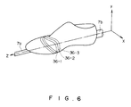
- the three-dimensional shape of the completed last is shown in FIGURE 6, in which distances from the Z-axis to points at the same X-coordinate or Y-coordinate on contour lines 36-1, 36-2, 36-3, ... depicting cross-sections of the last perpendicular to the Z-axis may include different ones.
- the cross-sections of the three-dimensional shape of the last include non-circular cross-sections.
- the movement data is data in accordance with which the rotating cutter 14 is moved along the X-axis and the Z-axis in such a manner that if the last having a predetermined three-dimensional shape to be prepared from the workpiece 6 were rotated about the Z-axis, the surface of the body of revolution of the rotating cutter 14 would contact the surface of the last at respective rotational positions of the last.
- the movement data comprises data of a reference point, e.g. the tip end P 5 , for the rotating milling cutter 14, e.g. data of the X coordinate x j of the tip end P 5 of the milling cutter 14, at the Z coordinate Z i of the reference point P 5 shown in FIGURE 5 when the workpiece 6 is rotated from its reference position by an angle of ⁇ .
- the Z coordinate z i of the reference point P 5 changes by, for example, 0.5 mm over the range of from a location on the toe side shaft-like portion 7a to a location on the heel end side shaft-like portion 7b of the last.
- the angle ⁇ is incremented by, for example, 1°, and preferably an angle of from 0.1° to 1°, over a range of from 0° (the reference position) to 360°.
- additional movement data is required, in accordance with which the cutter 14 is to be additionally moved along the Z-axis over a distance corresponding to the thickness of the cutter 14.
- Such additional movement data is not taken into account in the above calculation, but it is stored in the floppy disc.
- an operator mounts a workpiece 6 to be worked on the bearings 5a and 5b, and turns on the operating switch in the input unit 34 (FIGURE 2).
- the CPU 33 drives the milling cutter driving motor 19 to rotate the cutter 14 in the predetermined direction at a predetermined speed.
- the CPU 33 causes the milling cutter 14 to move to a position where the reference point P 5 on the milling cutter 14 is positioned near the heel-side shaft-like portion 7b.
- the movement of the milling cutter 14 is carried out by operating the X-direction and Z-direction driving motors 26 and 30 in accordance with the movement data stored in the memory unit 35.
- the CPU 33 operates the workpiece driving motor 11, the X-direction driving motor 26 and the Z-direction driving motor 30 in accordance with the movement data to cut the workpiece 6 into the last shown in FIGURE 6.
- the rotating milling cutter 14 can move to a position where the reference point P 5 on the cutter 14 shown in FIGURE 5 assumes an X coordinate x j when the reference point P 5 is at the Z coordinate z i and the workpiece 6 is at a rotational position spaced from its reference position by an angle ⁇ .
- the milling cutter 14 were moved along both the X-axis and the Z-axis in accordance with the movement data, and, at the same time, the completed last were rotated about the Z-axis, the surface of the body of revolution of the rotating milling cutter 14 would contact the surface of the last at each rotational position of the last.
- the workpiece 6 can be processed into a last having an exactly desired shape.
- the movement data (z, ⁇ , x) is prepared by computing the position, on the Z-X plane, of the milling cutter 14 when the surface of the last rotating about the Z-axis, as represented by the last coordinate data (x, y, z) contacts the surface of the body of revolution of the cutter edges 37 as expressed in the section 1-(5). Such position of the milling cutter 14 is determined for each of the rotational positions of the last.
- the computation is performed by the following steps (1)-(8).
- the processing steps (1)-(8) are performed by the CPU of the personal computer.
- the program in accordance with which the CPU uses to compute the movement data is stored in the memory unit connected to the CPU.
- the processing according to the steps (1)-(8) can eliminate error in processing which would otherwise be caused by the fact that the position where the cutting edges 37 cut the workpiece 6 varies due to the non-circular shape of the respective cross-sections of the last.
- the processing according to the steps (1) through (8) can also eliminate error in processing which would otherwise be caused by the shape and thickness of the cutting edges 37, which is semi-circular with the radius r of 10 mm.
- the rotation axis 15 of the milling cutter 14 is placed at an angle of ⁇ with respect to the Z-axis in order to provide a spacing between the side of the cutter 14 and the workpiece 6, which can prevent the contact between them.
- the above-described processing machine with a numerical control apparatus can be used to manufacture not only a last for shoes, but also other models and wooden, plastic or metallic specimens of articles.
- the present invention can be used with a machine with a rotary grindstone for processing a workpiece 6.
- stepping motors which have been described as being used as the workpiece driving motor 11
- the X-direction driving motor 26 and the Z-direction driving motor 30 stepping motors may be used.
- the workpiece 6 may be moved, while the milling cutter 14 is kept stationary.
Landscapes
- Engineering & Computer Science (AREA)
- Life Sciences & Earth Sciences (AREA)
- Manufacturing & Machinery (AREA)
- Mechanical Engineering (AREA)
- Wood Science & Technology (AREA)
- Forests & Forestry (AREA)
- Human Computer Interaction (AREA)
- Physics & Mathematics (AREA)
- General Physics & Mathematics (AREA)
- Automation & Control Theory (AREA)
- Numerical Control (AREA)
- Milling Processes (AREA)
Applications Claiming Priority (4)
| Application Number | Priority Date | Filing Date | Title |
|---|---|---|---|
| JP34725397 | 1997-12-01 | ||
| JP34725397A JP3740265B2 (ja) | 1997-12-01 | 1997-12-01 | 切刃の移動データを算出するためのプログラムを記録した記憶媒体 |
| JP347253/97 | 1997-12-01 | ||
| US09/420,268 US20010026740A1 (en) | 1997-12-01 | 1999-10-18 | Processing machine with numerical control apparatus |
Publications (2)
| Publication Number | Publication Date |
|---|---|
| EP0919893A2 true EP0919893A2 (fr) | 1999-06-02 |
| EP0919893A3 EP0919893A3 (fr) | 2000-09-13 |
Family
ID=26578462
Family Applications (1)
| Application Number | Title | Priority Date | Filing Date |
|---|---|---|---|
| EP98309800A Withdrawn EP0919893A3 (fr) | 1997-12-01 | 1998-11-30 | Machine d'usinage avec appareil à commande numérique |
Country Status (3)
| Country | Link |
|---|---|
| US (1) | US20010026740A1 (fr) |
| EP (1) | EP0919893A3 (fr) |
| JP (1) | JP3740265B2 (fr) |
Cited By (2)
| Publication number | Priority date | Publication date | Assignee | Title |
|---|---|---|---|---|
| CN106181393A (zh) * | 2016-08-31 | 2016-12-07 | 福州旭乐数控设备有限公司 | 鞋楦粗加工复合机及加工方法 |
| CN111152276A (zh) * | 2019-12-12 | 2020-05-15 | 龚清旺 | 一种鞋楦切割机 |
Families Citing this family (8)
| Publication number | Priority date | Publication date | Assignee | Title |
|---|---|---|---|---|
| CH696429A5 (de) * | 2002-01-31 | 2007-06-15 | Alstom Technology Ltd | Verfahren und Vorrichtung zur Rundum-Bearbeitung eines Rohlings. |
| CN100363849C (zh) * | 2004-08-04 | 2008-01-23 | 鼎维工业股份有限公司 | 加工铣刀的参数设定方法 |
| US9839253B2 (en) * | 2014-12-10 | 2017-12-12 | Nike, Inc. | Last system for braiding footwear |
| US10060057B2 (en) | 2015-05-26 | 2018-08-28 | Nike, Inc. | Braiding machine with non-circular geometry |
| US10238176B2 (en) | 2015-05-26 | 2019-03-26 | Nike, Inc. | Braiding machine and method of forming a braided article using such braiding machine |
| US10280538B2 (en) | 2015-05-26 | 2019-05-07 | Nike, Inc. | Braiding machine and method of forming an article incorporating a moving object |
| US9920462B2 (en) | 2015-08-07 | 2018-03-20 | Nike, Inc. | Braiding machine with multiple rings of spools |
| CN113798919B (zh) * | 2021-09-18 | 2022-07-26 | 清华大学 | 一种切削力测量方法、装置、电子设备及存储介质 |
Family Cites Families (5)
| Publication number | Priority date | Publication date | Assignee | Title |
|---|---|---|---|---|
| JPS5424156B1 (fr) * | 1971-02-03 | 1979-08-18 | ||
| WO1985000676A1 (fr) * | 1983-07-28 | 1985-02-14 | The Boeing Company | Procede d'usinage de contours tridimensionnels utilisant un tour a commande numerique |
| JPS60263211A (ja) * | 1984-06-11 | 1985-12-26 | Toyoda Mach Works Ltd | 対話形数値制御工作機械のデ−タ入力装置 |
| US5677855A (en) * | 1995-01-31 | 1997-10-14 | Smith & Nephew, Inc. | Method of generating grinding paths from a computer model for controlling a numerically controlled grinder |
| JP3490534B2 (ja) * | 1995-03-23 | 2004-01-26 | オークマ株式会社 | 非円形工作物の研削加工方法及び装置 |
-
1997
- 1997-12-01 JP JP34725397A patent/JP3740265B2/ja not_active Expired - Fee Related
-
1998
- 1998-11-30 EP EP98309800A patent/EP0919893A3/fr not_active Withdrawn
-
1999
- 1999-10-18 US US09/420,268 patent/US20010026740A1/en not_active Abandoned
Cited By (3)
| Publication number | Priority date | Publication date | Assignee | Title |
|---|---|---|---|---|
| CN106181393A (zh) * | 2016-08-31 | 2016-12-07 | 福州旭乐数控设备有限公司 | 鞋楦粗加工复合机及加工方法 |
| CN106181393B (zh) * | 2016-08-31 | 2018-03-06 | 福州旭乐数控设备有限公司 | 鞋楦粗加工复合机及加工方法 |
| CN111152276A (zh) * | 2019-12-12 | 2020-05-15 | 龚清旺 | 一种鞋楦切割机 |
Also Published As
| Publication number | Publication date |
|---|---|
| EP0919893A3 (fr) | 2000-09-13 |
| US20010026740A1 (en) | 2001-10-04 |
| JPH11161316A (ja) | 1999-06-18 |
| JP3740265B2 (ja) | 2006-02-01 |
Similar Documents
| Publication | Publication Date | Title |
|---|---|---|
| US5193314A (en) | Computer controlled grinding machine for producing objects with complex shapes | |
| KR0174275B1 (ko) | 에어포일의 가공 방법 | |
| EP0919893A2 (fr) | Machine d'usinage avec appareil à commande numérique | |
| US6022132A (en) | Method and apparatus for programming a CNC machine with a probe | |
| US12090596B2 (en) | Control device for machine tool and machine tool | |
| CN102814706B (zh) | 自由形态切割机 | |
| EP3799996B1 (fr) | Système et méthode de découpe avec une torche plasma | |
| KR100222372B1 (ko) | 프리즘형의 문자와 그래픽 이미지를 가진 표지를 생성하기 위한 방법 및 장치 | |
| EP0784253A1 (fr) | Méthode et appareil pour la programmation d'une machine à commande numérique | |
| KR100310814B1 (ko) | 스크롤상공작물의가공방법및장치 | |
| JP4443026B2 (ja) | インコーナ切削加工方法および数値制御装置 | |
| JPS6399114A (ja) | ポリゴン加工制御装置 | |
| JPH11138321A (ja) | カムシャフト加工機 | |
| US12350749B2 (en) | Gear machining apparatus | |
| US6658317B2 (en) | Method for setting a moving position in a machine tool | |
| JPH033716A (ja) | デバリング方法 | |
| JPS6384845A (ja) | 非真円形工作物の加工方法 | |
| JPH10118889A (ja) | 切削条件決定方法 | |
| CN1162240C (zh) | 钥匙铣齿机 | |
| JPH11179628A (ja) | Nc工作機械 | |
| US5368422A (en) | Method for manufacturing golf club heads or their prototypes | |
| JP2001269816A (ja) | 歯車加工方法及び歯車加工装置 | |
| JP3748099B2 (ja) | 切削加工方法及びこの切削加工方法を行うためのncデータ作成装置 | |
| JP2021171864A (ja) | 歯車加工装置 | |
| US5178498A (en) | X-Z-Theta cutting method |
Legal Events
| Date | Code | Title | Description |
|---|---|---|---|
| PUAI | Public reference made under article 153(3) epc to a published international application that has entered the european phase |
Free format text: ORIGINAL CODE: 0009012 |
|
| AK | Designated contracting states |
Kind code of ref document: A2 Designated state(s): DE FR IT |
|
| AX | Request for extension of the european patent |
Free format text: AL;LT;LV;MK;RO;SI |
|
| PUAL | Search report despatched |
Free format text: ORIGINAL CODE: 0009013 |
|
| AK | Designated contracting states |
Kind code of ref document: A3 Designated state(s): AT BE CH CY DE DK ES FI FR GB GR IE IT LI LU MC NL PT SE |
|
| AX | Request for extension of the european patent |
Free format text: AL;LT;LV;MK;RO;SI |
|
| RIC1 | Information provided on ipc code assigned before grant |
Free format text: 7G 05B 19/18 A, 7G 05B 19/41 B, 7G 05B 19/4099 B |
|
| 17P | Request for examination filed |
Effective date: 20010306 |
|
| AKX | Designation fees paid |
Free format text: DE FR IT |
|
| 17Q | First examination report despatched |
Effective date: 20020410 |
|
| STAA | Information on the status of an ep patent application or granted ep patent |
Free format text: STATUS: THE APPLICATION IS DEEMED TO BE WITHDRAWN |
|
| 18D | Application deemed to be withdrawn |
Effective date: 20020821 |