EP0920011A1 - Cartouche de disque magnetique - Google Patents
Cartouche de disque magnetique Download PDFInfo
- Publication number
- EP0920011A1 EP0920011A1 EP96926590A EP96926590A EP0920011A1 EP 0920011 A1 EP0920011 A1 EP 0920011A1 EP 96926590 A EP96926590 A EP 96926590A EP 96926590 A EP96926590 A EP 96926590A EP 0920011 A1 EP0920011 A1 EP 0920011A1
- Authority
- EP
- European Patent Office
- Prior art keywords
- shutter
- magnetic disk
- bending
- sheet member
- shutter member
- Prior art date
- Legal status (The legal status is an assumption and is not a legal conclusion. Google has not performed a legal analysis and makes no representation as to the accuracy of the status listed.)
- Withdrawn
Links
- 238000005452 bending Methods 0.000 claims abstract description 26
- 230000002093 peripheral effect Effects 0.000 claims description 4
- 238000005299 abrasion Methods 0.000 abstract description 4
- 239000000843 powder Substances 0.000 abstract description 3
- 239000000428 dust Substances 0.000 description 4
- 230000009545 invasion Effects 0.000 description 4
- 239000002184 metal Substances 0.000 description 4
- 239000000463 material Substances 0.000 description 3
- 230000007246 mechanism Effects 0.000 description 3
- 238000003780 insertion Methods 0.000 description 1
- 230000037431 insertion Effects 0.000 description 1
- 210000003141 lower extremity Anatomy 0.000 description 1
- 239000002991 molded plastic Substances 0.000 description 1
- 239000004033 plastic Substances 0.000 description 1
- 238000004080 punching Methods 0.000 description 1
- 238000004513 sizing Methods 0.000 description 1
- 210000001364 upper extremity Anatomy 0.000 description 1
Images

Classifications
-
- G—PHYSICS
- G11—INFORMATION STORAGE
- G11B—INFORMATION STORAGE BASED ON RELATIVE MOVEMENT BETWEEN RECORD CARRIER AND TRANSDUCER
- G11B23/00—Record carriers not specific to the method of recording or reproducing; Accessories, e.g. containers, specially adapted for co-operation with the recording or reproducing apparatus ; Intermediate mediums; Apparatus or processes specially adapted for their manufacture
- G11B23/02—Containers; Storing means both adapted to cooperate with the recording or reproducing means
- G11B23/03—Containers for flat record carriers
- G11B23/033—Containers for flat record carriers for flexible discs
-
- G—PHYSICS
- G11—INFORMATION STORAGE
- G11B—INFORMATION STORAGE BASED ON RELATIVE MOVEMENT BETWEEN RECORD CARRIER AND TRANSDUCER
- G11B23/00—Record carriers not specific to the method of recording or reproducing; Accessories, e.g. containers, specially adapted for co-operation with the recording or reproducing apparatus ; Intermediate mediums; Apparatus or processes specially adapted for their manufacture
- G11B23/02—Containers; Storing means both adapted to cooperate with the recording or reproducing means
- G11B23/03—Containers for flat record carriers
- G11B23/0301—Details
- G11B23/0308—Shutters
Definitions
- the present invention relates to a magnetic disk cartridge, more particularly to an improved structure of a shutter for opening and closing a magnetic head access opening in a magnetic disk cartridge having a rotatable magnetic disk encased in a cassette shell.
- a magnetic disk cartridge comprises a magnetic disk for magnetically recording analog and/or digital signals rotatably encased in a thin cassette shell.
- the cassette shell is formed in the shape of a flat prism (substantially a hexahedron) with a top surface slightly larger than the magnetic disk, a bottom surface having an opening through which a center core supporting the center of the magnetic disk is exposed and narrow side surfaces extending between the outer peripheral edges of the top and bottom surfaces.
- the magnetic disk cartridge is provided with a magnetic head access opening for insertion/withdrawal of magnetic heads used for magnetic recording and reproducing so as to enable the magnetic heads to be brought into contact with, or close to, the opposite surfaces of the magnetic disk from the exterior.
- the magnetic head access opening is equipped with a shutter member for preventing invasion of dust and the like when the magnetic disk cartridge is not in use.
- the magnetic head access opening of the prior art magnetic disk cartridge is a slender opening of substantially rectangular shape formed in the top and bottom surfaces of the cassette shell to extend in the radial direction of the magnetic disk.
- the shutter member for opening/closing the magnetic head access opening is a piece of thin sheet metal of -shaped section which extends along both the top and bottom surfaces of the cassette shell and also over the side surface between them.
- the magnetic head access opening it is not absolutely necessary for the magnetic head access opening to be formed in the top and bottom surfaces of the cassette shell to extend in the radial direction of the magnetic disk. Specifically, it can be provided at any location so long as it enables the magnetic heads to be brought in contact with, or close to, the opposite surfaces of the magnetic disk over the full radius thereof from the exterior.
- the opening is preferably as small as possible so as to minimize invasion of dust into the cartridge.
- the ability to fabricate smaller magnetic heads has afforded greater freedom in the positioning and sizing of the magnetic head access opening and has even made it possible to realize the desired small magnetic head access opening by providing the opening only in a side surface rather than in the top and/or bottom surface.
- the shutter member for opening and closing this type of magnetic head access opening has, as interconnected, an upper wing, a lower wing and a shutter section extending along the top and bottom surfaces and one side surface of the cassette shell, respectively, and the shutter section is provided with a window for opening the magnetic head access opening.
- the shutter member is obtained by first punching a sheet material (sheet metal or the like) to form a sheet member of prescribed developed (flat) shape while simultaneously forming the shutter window, and then bending the sheet member into -shape.
- the object of this invention is to overcome the aforesaid problems by providing a magnetic disk cartridge wherein deformation of the shutter member at the bent edge portions of the shutter window is prevented to enable opening and closing of the magnetic head access opening by sliding the shutter member along the cassette shell while maintaining an optimum state of abrasion-free contact therewith.
- the present invention provides a magnetic disk cartridge comprising a cassette shell formed as a flat prism with a top surface slightly larger than a magnetic disk encased in the cassette shell, a bottom surface of approximately the same shape as, and parallel to, the top surface, and narrow side surfaces extending between outer peripheral edges of the top and bottom surfaces, a magnetic head access opening formed in one side surface of the cassette shell for enabling magnetic reproducing and recording heads to be brought in contact with, or close to, opposite surfaces of the magnetic disk from the exterior, and a shutter member constituted as a sectionally -shaped sheet member formed of an upper wing, a shutter section with a shutter window and a lower wing that are interconnected and extend respectively along said top, one side and bottom surfaces, wherein the shutter member is provided on the cassette shell to be slidable along said surfaces for enabling the shutter window of the shutter section to open and close the magnetic head access opening, the shutter member is formed by bending the sheet member from an initial flat state, and the window is formed in the flat sheet member before bending to have upper and
- Each bent portion of the shutter member preferably has a radius of curvature equal to or greater than the sheet member thickness.
- the invention provides the magnetic head access opening of the magnetic disk cartridge in one side surface of the cassette shell, the magnetic head access opening can be made small to minimize invasion of dust and the like into the interior of the cartridge.
- the shutter member for opening and closing the magnetic head access opening which is constituted as a sectionally -shaped sheet member formed by interconnecting an upper wing, a shutter section and a lower wing that extend respectively along the top, one side and bottom surfaces of the cassette shell, is fabricated from a flat sheet member formed with a window at the portion destined to become the shutter section by bending the flat sheet member along bending lines in such manner that each of the upper and lower edges of the shutter window is defined to fall farther toward the outer edge of the sheet member than the corresponding bending line by a distance which is at least three times the magnitude of the thickness of the sheet member.
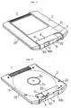
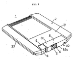
- FIGS 1 to 3 show a magnetic disk cartridge which is an embodiment of the invention.
- the magnetic disk cartridge is shown in perspective view from the top with its shutter member closed in Figure 1, from the bottom with its shutter member closed in Figure 2, and from the top with its shutter member open in Figure 3.
- the center portion of the magnetic disk 3 (recording medium) is fixed to a rotating member 3a.
- the rotating member 3a faces into a circular opening 2a in the bottom surface 22 of the cassette shell 2 (see Figure 2).
- the rotating member 3a is adapted to be engaged by a spindle for rapidly rotating the magnetic disk 3.
- a slidable shutter member 8 for opening and closing the magnetic head access opening 6 is provided on the cassette shell 2.
- the shutter member 8 is constituted as a sectionally -shaped metal sheet member comprising, as interconnected, an upper wing 81 extending along the top surface 21, a shutter section 82 extending along the one side surface 4 and a lower wing 83 extending along the bottom surface 22.
- the shutter member 8 moves along these surfaces. It is further provided with a shutter window 82a. It can therefore open and close the magnetic head access opening 6 depending whether the magnetic disk cartridge 1 is in storage or operation.
- portions of the top surface 21, the side surface 4 and the bottom surface 22 of the cassette shell 2 adjacent to the magnetic head access opening 6 are formed with a shallow recess 9 for retaining and guiding the upper wing 81, the shutter section 82 and the lower wing 83 of the shutter member 8.
- the upper wing 81, shutter section 82 and lower wing 83 of the shutter member 8 are received in and guided by the recess 9 to be slidable laterally along the surfaces of the cassette shell 2.
- the magnetic disk cartridge 1 of this embodiment is used in the same manner as the prior-art magnetic disk cartridge. Specifically, it is loaded into the magnetic recording and reproducing device (hereinafter called simply "device") in the state shown in Figure 1, i.e. with the magnetic head access opening 6 closed by the shutter member 8. At this time, an operating member provided in the device responds to the loading operation by sliding the shutter member 8 to the open position shown in Figure 3. Then, when the operator performs a prescribed operation for removing the magnetic disk cartridge from the device, for instance, when the operator presses a prescribed operating button of the device, the operating member of the device responds by closing the shutter member 8 to the position shown in Figure 1.
- the magnetic recording and reproducing device hereinafter called simply "device"
- each of the upper and lower edges of the shutter window 82a is defined to fall farther toward the outer edge of the sheet member (in the direction of the upper wing 81 or the lower wing 83) than the corresponding bending line A by a distance d which is at least three times the magnitude of the thickness t of the sheet member. Since the shutter window 82a is therefore defined to extend from within the region of the upper wing 81 to within the region of the lower wing 83, the accuracy to which the positioning of the bending lines is required to be controlled during the bending operation for defining the shutter section 82 is lower than in the past.
- the cassette shell 2 is preferably provided with biasing means (e.g., a spring) for urging the shutter member 8 in the closing direction. Since such a biasing means also serves to retain the shutter member 8 in the closed position at all times when the cartridge is not in use, its provision is also preferable from the viewpoint of preventing invasion of dust and the like.
- biasing means e.g., a spring
Landscapes
- Feeding And Guiding Record Carriers (AREA)
Applications Claiming Priority (1)
| Application Number | Priority Date | Filing Date | Title |
|---|---|---|---|
| PCT/JP1996/002235 WO1998007151A1 (fr) | 1996-08-08 | 1996-08-08 | Cartouche de disque magnetique |
Publications (2)
| Publication Number | Publication Date |
|---|---|
| EP0920011A1 true EP0920011A1 (fr) | 1999-06-02 |
| EP0920011A4 EP0920011A4 (fr) | 1999-08-11 |
Family
ID=14153655
Family Applications (1)
| Application Number | Title | Priority Date | Filing Date |
|---|---|---|---|
| EP96926590A Withdrawn EP0920011A4 (fr) | 1996-08-08 | 1996-08-08 | Cartouche de disque magnetique |
Country Status (3)
| Country | Link |
|---|---|
| EP (1) | EP0920011A4 (fr) |
| CA (1) | CA2262703C (fr) |
| WO (1) | WO1998007151A1 (fr) |
Cited By (1)
| Publication number | Priority date | Publication date | Assignee | Title |
|---|---|---|---|---|
| FR2816441A1 (fr) * | 2000-11-03 | 2002-05-10 | Albi Media Mfg | Cartouche de disque magnetique |
Family Cites Families (8)
| Publication number | Priority date | Publication date | Assignee | Title |
|---|---|---|---|---|
| US4503474A (en) * | 1982-06-04 | 1985-03-05 | Syquest Technology | Disc drive cartridge arrangement |
| JPS6043280A (ja) * | 1983-08-04 | 1985-03-07 | シクエスト・テクノロジ− | ハ−ドデイスクカ−トリツジ装置 |
| JPS6289287A (ja) * | 1985-10-16 | 1987-04-23 | Hitachi Ltd | 記録媒体保護ケ−ス |
| JPS62164657U (fr) * | 1986-04-07 | 1987-10-19 | ||
| IE891454L (en) * | 1989-05-04 | 1990-11-04 | Bray Prec Tooling Co Ltd | Forming a micro disc shutter |
| JPH0371480U (fr) * | 1989-11-13 | 1991-07-19 | ||
| EP0576719A1 (fr) * | 1992-07-03 | 1994-01-05 | Sigma Japan Co., Ltd. | Procédé de fabrication d'un obturateur en une pièce pour l'orifice dans la cartouche d'une disquette, en particulier pour une microdisquette à partir d'un matériaux sans fin |
| US5650891A (en) * | 1994-10-18 | 1997-07-22 | Iomega Corporation | Apparatus for performing multiple functions in a data storage device using a single electro-mechanical device |
-
1996
- 1996-08-08 EP EP96926590A patent/EP0920011A4/fr not_active Withdrawn
- 1996-08-08 WO PCT/JP1996/002235 patent/WO1998007151A1/fr not_active Ceased
- 1996-08-08 CA CA002262703A patent/CA2262703C/fr not_active Expired - Fee Related
Cited By (1)
| Publication number | Priority date | Publication date | Assignee | Title |
|---|---|---|---|---|
| FR2816441A1 (fr) * | 2000-11-03 | 2002-05-10 | Albi Media Mfg | Cartouche de disque magnetique |
Also Published As
| Publication number | Publication date |
|---|---|
| WO1998007151A1 (fr) | 1998-02-19 |
| EP0920011A4 (fr) | 1999-08-11 |
| CA2262703A1 (fr) | 1998-02-19 |
| CA2262703C (fr) | 2002-01-01 |
Similar Documents
| Publication | Publication Date | Title |
|---|---|---|
| US6094327A (en) | Disk drive cartridge door | |
| EP0778571B1 (fr) | Cassette à disque | |
| EP0406943A1 (fr) | Système d'enregistrement/reproduction de signaux sur/de bande magnétique, et appareil et cassette à utiliser dans ce système | |
| JP2520275Y2 (ja) | ディスクカセット | |
| EP0421775B1 (fr) | Cassette à disque | |
| US5724217A (en) | Magnetic disk cartridge with shutter spring engaging portion and guide projection | |
| US6023398A (en) | Disk cartridge with rotatable cartridge door | |
| US5761015A (en) | Magnetic disk cartridge having a shutter member provided with a slit at a corner portion | |
| CA2262703C (fr) | Cartouche de disque magnetique | |
| EP0059946B1 (fr) | Cassette à bande | |
| EP0459743A2 (fr) | Cassettes à disques et procédé de fabrication de telles cassettes | |
| EP0918329B1 (fr) | Cartouche de disque magnetique | |
| EP0920012B1 (fr) | Cartouche de disque magnetique | |
| US5892642A (en) | Magnetic disk cartridge | |
| CA2262638C (fr) | Cartouche de disque magnetique | |
| EP0557726A2 (fr) | Lecteur de cassette à bande compatible avec des cassettes à bande de différent format | |
| US5237479A (en) | Tape cassette with slidable cover | |
| JP3478356B2 (ja) | 磁気ディスクカートリッジ | |
| US5898551A (en) | Magnetic disk cartridge | |
| JP2632546B2 (ja) | 磁気テープカートリッジ | |
| JP3502894B2 (ja) | 磁気ディスクカートリッジ | |
| JPH0624073Y2 (ja) | 磁気テープカートリッジ | |
| EP0920009A1 (fr) | Cartouche de disque magnetique | |
| JPH08221932A (ja) | 磁気ディスクカートリッジ | |
| JPS63171486A (ja) | ディスクカセット |
Legal Events
| Date | Code | Title | Description |
|---|---|---|---|
| PUAI | Public reference made under article 153(3) epc to a published international application that has entered the european phase |
Free format text: ORIGINAL CODE: 0009012 |
|
| 17P | Request for examination filed |
Effective date: 19990226 |
|
| AK | Designated contracting states |
Kind code of ref document: A1 Designated state(s): DE FR GB IT |
|
| A4 | Supplementary search report drawn up and despatched |
Effective date: 19990624 |
|
| AK | Designated contracting states |
Kind code of ref document: A4 Designated state(s): DE FR GB IT |
|
| 17Q | First examination report despatched |
Effective date: 20020314 |
|
| STAA | Information on the status of an ep patent application or granted ep patent |
Free format text: STATUS: THE APPLICATION IS DEEMED TO BE WITHDRAWN |
|
| 18D | Application deemed to be withdrawn |
Effective date: 20020725 |