EP0920083B1 - Assemblage de connexion électrique avec un bloc de jonction ayant une face laterale prolongée - Google Patents
Assemblage de connexion électrique avec un bloc de jonction ayant une face laterale prolongée Download PDFInfo
- Publication number
- EP0920083B1 EP0920083B1 EP98122384A EP98122384A EP0920083B1 EP 0920083 B1 EP0920083 B1 EP 0920083B1 EP 98122384 A EP98122384 A EP 98122384A EP 98122384 A EP98122384 A EP 98122384A EP 0920083 B1 EP0920083 B1 EP 0920083B1
- Authority
- EP
- European Patent Office
- Prior art keywords
- semi
- cylinder
- junction block
- connection unit
- pull
- Prior art date
- Legal status (The legal status is an assumption and is not a legal conclusion. Google has not performed a legal analysis and makes no representation as to the accuracy of the status listed.)
- Expired - Lifetime
Links
- 230000000295 complement effect Effects 0.000 claims description 4
- 210000000078 claw Anatomy 0.000 description 4
- 238000010276 construction Methods 0.000 description 2
- 238000003780 insertion Methods 0.000 description 2
- 230000037431 insertion Effects 0.000 description 2
- 238000004078 waterproofing Methods 0.000 description 2
- 238000010668 complexation reaction Methods 0.000 description 1
- 238000009434 installation Methods 0.000 description 1
- 238000012986 modification Methods 0.000 description 1
- 230000004048 modification Effects 0.000 description 1
- 230000000717 retained effect Effects 0.000 description 1
Images

Classifications
-
- H—ELECTRICITY
- H01—ELECTRIC ELEMENTS
- H01R—ELECTRICALLY-CONDUCTIVE CONNECTIONS; STRUCTURAL ASSOCIATIONS OF A PLURALITY OF MUTUALLY-INSULATED ELECTRICAL CONNECTING ELEMENTS; COUPLING DEVICES; CURRENT COLLECTORS
- H01R13/00—Details of coupling devices of the kinds covered by groups H01R12/70 or H01R24/00 - H01R33/00
- H01R13/46—Bases; Cases
- H01R13/516—Means for holding or embracing insulating body, e.g. casing, hoods
- H01R13/518—Means for holding or embracing insulating body, e.g. casing, hoods for holding or embracing several coupling parts, e.g. frames
-
- H—ELECTRICITY
- H01—ELECTRIC ELEMENTS
- H01R—ELECTRICALLY-CONDUCTIVE CONNECTIONS; STRUCTURAL ASSOCIATIONS OF A PLURALITY OF MUTUALLY-INSULATED ELECTRICAL CONNECTING ELEMENTS; COUPLING DEVICES; CURRENT COLLECTORS
- H01R13/00—Details of coupling devices of the kinds covered by groups H01R12/70 or H01R24/00 - H01R33/00
- H01R13/66—Structural association with built-in electrical component
-
- Y—GENERAL TAGGING OF NEW TECHNOLOGICAL DEVELOPMENTS; GENERAL TAGGING OF CROSS-SECTIONAL TECHNOLOGIES SPANNING OVER SEVERAL SECTIONS OF THE IPC; TECHNICAL SUBJECTS COVERED BY FORMER USPC CROSS-REFERENCE ART COLLECTIONS [XRACs] AND DIGESTS
- Y10—TECHNICAL SUBJECTS COVERED BY FORMER USPC
- Y10S—TECHNICAL SUBJECTS COVERED BY FORMER USPC CROSS-REFERENCE ART COLLECTIONS [XRACs] AND DIGESTS
- Y10S439/00—Electrical connectors
- Y10S439/949—Junction box with busbar for plug-socket type interconnection with receptacle
Definitions
- the present Invention is directed to an electrical connection unit which contains a junction block and a main box.
- the unit is primarily intended for mounting in the engine compartment of a vehicle and to provide power to various electrical elements contained therein or used therewith.
- a typical prior art unit of the same general type as claimed herein comprises a connector with a wire harness extending therefrom.
- the connector is directly assembled with a junction block on which electrical parts such as fuses or relays are mounted. It is also known to have such a unit wherein the junction block is mounted in a main box and the connector is mounted in the junction block.
- a cover is attached to the lower end of a side wall of the block or main box which seals the lower end thereof and provides desired waterproofing.
- a plurality of legs may be provided on the lower portion of the side wall of the junction block or main box which permits the block or box to be spaced apart from the portion of the vehicle body to which it is attached.
- EP-0 248 181 shows an electrical connection unit according to the preamble part of claim 1. It is an object of the present invention to further improve the connection unit to show a more compact size.
- At least one pull-out section is provided on the extended portion of the side walls and the wire harnesses pass therethrough. It has been found particularly advantageous if the pull-out section comprises first and second semi-cylinders which are complementary to each other. They are connected at one edge by a hinge, whereby the second semi-cylinder pivots about the hinge into contact with the first semi-cylinder, thereby retaining the wire harness in the pull-out section.
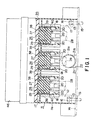
- connection unit comprises cover 46, junction block 35 and main box 11.
- Junction block 35 contains, for example, fuses 36 and relays 37. It is attached to main box 11 by fastening bolts 43. Projections 39 on the underside of junction block 35 fit into cavity grooves 19 and thereby guide junction block 35 into main box 11.
- Connectors 26 with female contacts 27 are inserted into main box 11 from the lower end as shown in Figure 2.
- Retainers 32 with insertion holes 30 are located on female contacts 27 so that fastening bolts 43, passing through bolt openings 41, engage nut 31 and secure junction block 35 to main box 11.
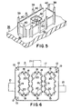
- Support plate 17 is at the center portion of main box 11 and connector cavities 18 are at predetermined intervals on the support plate. Claws 20 are located at the lower ends of connector cavities 18 and serve as support members. Harness opening 22 opens downward from the bottom end of side wall 11a of main box 11.
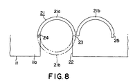
- First semi-cylinder 21a is integral with the upper edge of harness opening 22 and extends outward from the main box.
- Second semi-cylinder 21b is connected at one edge to first semi-cylinder 21a by hinge 23.
- second semi-cylinder 21b has an open position, as shown in full lines in Figure 8, and a closed position, as shown in broken lines in Figure 8.
- the edges of both semi-cylinders remote from hinge 23 are provided with female latch 24 and male latch 25. As can be seen best in Figure 8, when second semi-cylinder 21b is in its closed position, female latch 24 mates with male latch 25, whereby wire harness 28 (see Figures 1 and 7) is secured in pull-out section 21.
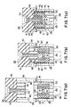
- connectors 26 are inserted into connector cavities 18 of main box 11 from below. They fit loosely in these cavities and are supported by claws 20 in the preliminary position as shown in Figure 7(a).
- Each wire harness 28 is connected to female contacts 27, extends from the lower portion of connectors 26, is passed through harness opening 22, and is secured in pull-out section 21 by first semi-cylinder 21a and second semi-cylinder 21b.
- Tapered surfaces 29 are on the upper outer edges of connectors 26. Insertion hole 30 is located vertically at the center of connector 26 and nut 31 is imbedded therein within retainer 32. The retainer prevents nut 31 from turning when fastening bolt 43 is inserted and tightened.
- junction block 35 is mounted inside main box 11 from above as shown in Figure 2.
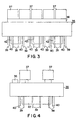
- Fuses 36 and relays 37 are mounted on the upper surface of junction block 35 and a plurality of male contacts 38, connected to these electrical parts, is mounted on the lower surface.
- projections 39 there is also provided a plurality of projections 39, in three groups in the present case, which extend from the lower surface of junction block 35 and surround male contacts 38.
- junction block 35 When junction block 35 is mounted in main box 11, projections 39 are inserted into and engaged in cavity grooves 19 in connector cavities 18. Slanted surfaces 40, at the lower inner perimeter edge of projections 39, bear against tapered surfaces 29, as junction block 35 enters main box 11 (see particularly Figures 7(b) and (c)). Engagement elements 42, in the form of four-sided rings, surround bolt openings 41 in junction block 35. Bolts 43, which serve as tightening means, are inserted into bolt openings 41 and are screwed into nuts 31 within connectors 26.
- junction block 35 is urged against connectors 26 and male contacts 38 are firmly connected to female contacts 27 when bolts 43 are fully tightened. Elements 42 engage retainers 32 of connectors 26, thus further securing junction block 35 in its assembled position. As shown in Figures 1 and 2, cover 46 is placed over the upper end of main box 11.
- Connector 26 is inserted into connector cavity 18 of main box 11 from below.
- Claws 20 loosely support connector 26 at a preliminary position.
- Wire harness 28, extending from connector 26, is passed through harness opening 22 which carries first semi-cylinder 21a at its upper end.
- second semi-cylinder 21b is pivoted about hinge 23 from the position as shown in solid lines in Figure 8 to the position shown in broken lines in Figure 8.
- Female latch 24 and male latch 25 are engaged to secure wire harness 28 in pull-out section 21.
- junction block 35 As junction block 35 is mounted, slanted surface 40 engages tapered surface 29.
- connector 26, which was loosely held in connector cavity 18, is both centered and moved to its connection position (see particularly Figure 7(b)).
- Fastening bolts 43 are passed through bolt openings 41 from above and are screwed into nuts 31, as shown in Figure 7(c).
- Engagement element 42 engages retainer 32, and fastening bolt 43 is screwed into nut 32 of connector 26.
- the final step is to place cover 46 over the upper surface of junction block 35. The assembly of the unit is now complete.
- a simplified waterproof connection unit can be provided, without the necessity of a bottom cover or the use of a plurality of legs bearing against the vehicle body.
- the wire harness can easily be passed through the space created by the extended side walls, led out through the harness opening, and secured by the pull-out section.
- the construction of the pull-out section permits wide opening of the semi-cylinders by pivoting the second semi-cylinder about the hinge in a direction away from the first semi-cylinder. When in this open position, it is an easy matter to lay the wire harness in the first semi-cylinder and, thereafter, pivot the second semi-cylinder about the hinge toward the first semi-cylinder. This closes the pull-out section and the male and female latches engage so as to secure it in this closed position. This provides a reliable means of locking the wire harness in its proper position.
- the main box be affixed to the vehicle body before the junction block is inserted.
Landscapes
- Connection Or Junction Boxes (AREA)
- Coupling Device And Connection With Printed Circuit (AREA)
Claims (5)
- Unité de connexion électrique adaptée pour être fixée sur une partie d'une caisse de véhicule (14), comprenant un bloc de jonction de jonction (35) et une pluralité de connecteurs (26), ledit bloc de jonction portant une pluralité d'éléments électriques (36, 37), lesdits connecteurs (26) étant montés sur ledit bloc de jonction (35) et en contact électrique avec lesdits éléments, une pluralité de faisceaux électriques (28) se prolongeant à partir desdits connecteurs,
et comprenant un boítier principal (11) enfermant lesdits connecteurs (26) et ayant des extensions qui forment des parois latérales(11a) qui se prolongent au-delà desdits connecteurs (26) dans un sens s'éloignant desdits éléments (36, 37) pour créer un espace entre lesdits connecteurs (26) et les bords inférieurs desdites parois latérales (11a) distantes desdits éléments, lesdits bords étant adaptés pour reposer contre ladite partie de ladite caisse du véhicule (14),
caractérisé en ce que les prolongements formant les parois latérales sont contiguës aux parois correspondantes dudit bloc de jonction (25). - Unité de connexion électrique selon la revendication 1, dans laquelle il y a au moins une section de décrochage (21) traversée par lesdits faisceaux électriques, ladite section de décrochage dépassant d'une parmi lesdites parois latérales.
- Unité de connexion électrique selon la revendication 2, dans laquelle ladite section de décrochage est placée entre ledit espace et une partie externe de ladite unité de connexion.
- Unité de connexion électrique selon la revendication 3, dans laquelle ladite section de décrochage comprend un premier demi-cylindre (21a) et un deuxième demi-cylindre (21b) complémentaire audit premier demi-cylindre, ledit deuxième demi-cylindre étant connecté audit premier demi-cylindre par une charnière (23), grâce à quoi ledit deuxième demi-cylindre peut se déplacer entre une première position, dans laquelle ledit premier demi-cylindre est ouvert pour recevoir ledit faisceau électrique, et une deuxième position, dans laquelle ledit deuxième demi-cylindre se referme par dessus le premier demi-cylindre, retenant ainsi ledit faisceau électrique dans ladite section de décrochage.
- Unité de connexion électrique selon la revendication 4, dans laquelle il y a un verrou femelle (24) sur un bord, distant de ladite charnière, d'un parmi ledit premier demi-cylindre et ledit deuxième demi-cylindre, et un verrou mâle (25), complémentaire audit verrou femelle, sur un bord, distant de ladite charnière, de l'autre parmi ledit premier demi-cylindre et ledit deuxième demi-cylindre, grâce à quoi ledit verrou mâle et ledit verrou femelle retiennent, de telle façon qu'ils pourront être déverrouillés, ladite section de décrochage dans ladite deuxième position.
Applications Claiming Priority (3)
| Application Number | Priority Date | Filing Date | Title |
|---|---|---|---|
| JP32316697A JP3248474B2 (ja) | 1997-11-25 | 1997-11-25 | 配電ボックス |
| JP32316697 | 1997-11-25 | ||
| JP323166/97 | 1997-11-25 |
Publications (2)
| Publication Number | Publication Date |
|---|---|
| EP0920083A1 EP0920083A1 (fr) | 1999-06-02 |
| EP0920083B1 true EP0920083B1 (fr) | 2004-03-03 |
Family
ID=18151824
Family Applications (1)
| Application Number | Title | Priority Date | Filing Date |
|---|---|---|---|
| EP98122384A Expired - Lifetime EP0920083B1 (fr) | 1997-11-25 | 1998-11-25 | Assemblage de connexion électrique avec un bloc de jonction ayant une face laterale prolongée |
Country Status (4)
| Country | Link |
|---|---|
| US (1) | US6010341A (fr) |
| EP (1) | EP0920083B1 (fr) |
| JP (1) | JP3248474B2 (fr) |
| DE (1) | DE69822086T2 (fr) |
Families Citing this family (19)
| Publication number | Priority date | Publication date | Assignee | Title |
|---|---|---|---|---|
| JP3506932B2 (ja) | 1998-12-09 | 2004-03-15 | 株式会社山武 | 半導体圧力センサ及びその製造方法 |
| DE19905952C2 (de) * | 1999-02-12 | 2001-04-05 | Sew Eurodrive Gmbh & Co | Verteilerkasten |
| JP2001314015A (ja) | 2000-04-27 | 2001-11-09 | Sumitomo Wiring Syst Ltd | コネクタ仮止め構造付きの電気接続箱 |
| JP2002186136A (ja) * | 2000-12-14 | 2002-06-28 | Yazaki Corp | 電気接続箱 |
| JP3945306B2 (ja) * | 2002-05-07 | 2007-07-18 | 住友電装株式会社 | 電気接続箱 |
| KR100516513B1 (ko) * | 2004-02-19 | 2005-09-26 | 타이코에이엠피 주식회사 | 차량용 정션박스 및 그 조립방법 |
| JP2006062563A (ja) * | 2004-08-27 | 2006-03-09 | Sumitomo Wiring Syst Ltd | 電気接続箱 |
| KR100823349B1 (ko) | 2007-06-28 | 2008-04-28 | 한국단자공업 주식회사 | 차량용 정션박스의 파워커넥터 결합 구조 |
| JP4825900B2 (ja) * | 2009-06-30 | 2011-11-30 | トヨタ自動車株式会社 | ジャンクションブロックおよび自動車 |
| JP5333849B2 (ja) * | 2009-07-10 | 2013-11-06 | 住友電装株式会社 | 電気接続箱 |
| DE102009036411B3 (de) * | 2009-08-06 | 2011-02-03 | Tyco Electronics Amp Gmbh | Kombinierter elektrischer Steckverbinder mit Toleranzausgleich |
| US8419479B2 (en) * | 2009-09-17 | 2013-04-16 | Matthew Leigh Vroom | Docking station for an electronic device with improved electrical interface |
| JP5608470B2 (ja) * | 2010-08-23 | 2014-10-15 | 矢崎総業株式会社 | 電気接続箱 |
| CN105140857A (zh) * | 2012-07-18 | 2015-12-09 | 茹朝贵 | 一种接线盒 |
| JP5822001B1 (ja) * | 2014-07-11 | 2015-11-24 | 株式会社明電舎 | アクチュエータ用フラットケーブル |
| GB2548741B (en) * | 2015-01-16 | 2021-09-08 | Halliburton Energy Services Inc | Collar-mountable bobbin antenna having coil and ferrite slots |
| US9257788B1 (en) * | 2015-01-23 | 2016-02-09 | Oracle International Corporation | Connector retention and alignment assembly for use in computer and data storage mounting racks |
| CN108535826A (zh) * | 2018-05-28 | 2018-09-14 | 江苏欣佰建设工程有限公司 | 一种家用光纤布线箱的箱盖结构 |
| CN109348666B (zh) * | 2018-11-12 | 2021-09-21 | 苏州佳世达光电有限公司 | 车载电子设备 |
Family Cites Families (6)
| Publication number | Priority date | Publication date | Assignee | Title |
|---|---|---|---|---|
| DE3619183A1 (de) * | 1986-06-06 | 1987-12-10 | Audi Ag | Sicherungs- und verteilerkasten fuer kraftfahrzeuge |
| US4954102A (en) * | 1988-03-25 | 1990-09-04 | Yazaki Corporation | Wiring connection apparatus |
| JPH01143231U (fr) * | 1988-03-25 | 1989-10-02 | ||
| US4956561A (en) * | 1988-12-27 | 1990-09-11 | Caterpillar Inc. | Smart power connector |
| JP2515735Y2 (ja) * | 1990-11-21 | 1996-10-30 | 住友電装株式会社 | ワイヤーハーネスのコネクタカバー |
| US5788529A (en) * | 1997-06-09 | 1998-08-04 | General Motors Corporation | Top down electrical distribution center assembly |
-
1997
- 1997-11-25 JP JP32316697A patent/JP3248474B2/ja not_active Expired - Fee Related
-
1998
- 1998-11-25 DE DE69822086T patent/DE69822086T2/de not_active Expired - Lifetime
- 1998-11-25 US US09/199,863 patent/US6010341A/en not_active Expired - Lifetime
- 1998-11-25 EP EP98122384A patent/EP0920083B1/fr not_active Expired - Lifetime
Also Published As
| Publication number | Publication date |
|---|---|
| DE69822086T2 (de) | 2009-09-24 |
| JPH11164445A (ja) | 1999-06-18 |
| EP0920083A1 (fr) | 1999-06-02 |
| US6010341A (en) | 2000-01-04 |
| DE69822086D1 (de) | 2004-04-08 |
| JP3248474B2 (ja) | 2002-01-21 |
Similar Documents
| Publication | Publication Date | Title |
|---|---|---|
| US6010341A (en) | Electrical connection unit with a junction block or main box having an extended side wall | |
| EP0920087B1 (fr) | Assemblage de connexion électrique | |
| CA1292047C (fr) | Prise d'electricite et son logement | |
| JPH0438468Y2 (fr) | ||
| EP1170828B1 (fr) | Couvercle de protection | |
| US7766695B1 (en) | Power inlet box with removable socket mounting member | |
| KR100641814B1 (ko) | 배선덕트의 연결구조 | |
| AU703483B2 (en) | Electrical assembly including a connection box having a junction block therein | |
| JP2597713Y2 (ja) | 分岐接続箱 | |
| US5190482A (en) | Bulkhead connector assembly | |
| JP3290387B2 (ja) | 電気接続箱 | |
| JPH0837054A (ja) | モジュール構造の電気的差し込みコネクタ装置 | |
| US6508452B2 (en) | Mounting device for mounting an electrical device on trunking | |
| JP3262979B2 (ja) | ヒュージブルリンクブロック用カバーの保持構造 | |
| JPH10302887A (ja) | 電気接続箱のコネクタ接続構造 | |
| CN216530359U (zh) | 线缆槽构件 | |
| JPH058743Y2 (fr) | ||
| JP2957063B2 (ja) | 電気接続箱 | |
| JP3248473B2 (ja) | 配電ボックス及びその組み付け方法 | |
| JP3669540B2 (ja) | 電気接続箱の端子取付け構造 | |
| JPH055667Y2 (fr) | ||
| EP0475798B1 (fr) | Boîte de montage modulaire pour appareil électrique | |
| JP3248472B2 (ja) | 配電ボックス | |
| JPS5821309Y2 (ja) | ケ−ブル布設用防災トラフ | |
| KR0119176Y1 (ko) | 자동차의 사이드미러용 도어 내측 커버패널 체결구조 |
Legal Events
| Date | Code | Title | Description |
|---|---|---|---|
| PUAI | Public reference made under article 153(3) epc to a published international application that has entered the european phase |
Free format text: ORIGINAL CODE: 0009012 |
|
| 17P | Request for examination filed |
Effective date: 19990211 |
|
| AK | Designated contracting states |
Kind code of ref document: A1 Designated state(s): DE FR GB IT |
|
| AX | Request for extension of the european patent |
Free format text: AL;LT;LV;MK;RO;SI |
|
| AKX | Designation fees paid |
Free format text: DE FR GB IT |
|
| 17Q | First examination report despatched |
Effective date: 20010528 |
|
| GRAH | Despatch of communication of intention to grant a patent |
Free format text: ORIGINAL CODE: EPIDOS IGRA |
|
| GRAS | Grant fee paid |
Free format text: ORIGINAL CODE: EPIDOSNIGR3 |
|
| GRAA | (expected) grant |
Free format text: ORIGINAL CODE: 0009210 |
|
| AK | Designated contracting states |
Kind code of ref document: B1 Designated state(s): DE FR GB IT |
|
| PG25 | Lapsed in a contracting state [announced via postgrant information from national office to epo] |
Ref country code: IT Free format text: LAPSE BECAUSE OF FAILURE TO SUBMIT A TRANSLATION OF THE DESCRIPTION OR TO PAY THE FEE WITHIN THE PRE;WARNING: LAPSES OF ITALIAN PATENTS WITH EFFECTIVE DATE BEFORE 2007 MAY HAVE OCCURRED AT ANY TIME BEFORE 2007. THE CORRECT EFFECTIVE DATE MAY BE DIFFERENT FROM THE ONE RECORDED.SCRIBED TIME-LIMIT Effective date: 20040303 Ref country code: FR Free format text: LAPSE BECAUSE OF FAILURE TO SUBMIT A TRANSLATION OF THE DESCRIPTION OR TO PAY THE FEE WITHIN THE PRESCRIBED TIME-LIMIT Effective date: 20040303 |
|
| REG | Reference to a national code |
Ref country code: GB Ref legal event code: FG4D |
|
| REF | Corresponds to: |
Ref document number: 69822086 Country of ref document: DE Date of ref document: 20040408 Kind code of ref document: P |
|
| PLBE | No opposition filed within time limit |
Free format text: ORIGINAL CODE: 0009261 |
|
| STAA | Information on the status of an ep patent application or granted ep patent |
Free format text: STATUS: NO OPPOSITION FILED WITHIN TIME LIMIT |
|
| EN | Fr: translation not filed | ||
| 26N | No opposition filed |
Effective date: 20041206 |
|
| PGFP | Annual fee paid to national office [announced via postgrant information from national office to epo] |
Ref country code: DE Payment date: 20101117 Year of fee payment: 13 |
|
| PGFP | Annual fee paid to national office [announced via postgrant information from national office to epo] |
Ref country code: GB Payment date: 20101124 Year of fee payment: 13 |
|
| GBPC | Gb: european patent ceased through non-payment of renewal fee |
Effective date: 20111125 |
|
| REG | Reference to a national code |
Ref country code: DE Ref legal event code: R119 Ref document number: 69822086 Country of ref document: DE Effective date: 20120601 |
|
| PG25 | Lapsed in a contracting state [announced via postgrant information from national office to epo] |
Ref country code: GB Free format text: LAPSE BECAUSE OF NON-PAYMENT OF DUE FEES Effective date: 20111125 |
|
| PG25 | Lapsed in a contracting state [announced via postgrant information from national office to epo] |
Ref country code: DE Free format text: LAPSE BECAUSE OF NON-PAYMENT OF DUE FEES Effective date: 20120601 |