EP0920101B1 - Kabelverbindung mit Erdungsverbindung und/oder Schirmauskreuzung für Energiekabl - Google Patents
Kabelverbindung mit Erdungsverbindung und/oder Schirmauskreuzung für Energiekabl Download PDFInfo
- Publication number
- EP0920101B1 EP0920101B1 EP97402882A EP97402882A EP0920101B1 EP 0920101 B1 EP0920101 B1 EP 0920101B1 EP 97402882 A EP97402882 A EP 97402882A EP 97402882 A EP97402882 A EP 97402882A EP 0920101 B1 EP0920101 B1 EP 0920101B1
- Authority
- EP
- European Patent Office
- Prior art keywords
- cable joint
- metallic member
- metallic
- tube
- cable
- Prior art date
- Legal status (The legal status is an assumption and is not a legal conclusion. Google has not performed a legal analysis and makes no representation as to the accuracy of the status listed.)
- Expired - Lifetime
Links
- 239000004020 conductor Substances 0.000 claims description 34
- 238000009413 insulation Methods 0.000 claims description 23
- 239000012212 insulator Substances 0.000 claims description 14
- 239000000463 material Substances 0.000 claims description 7
- 239000011521 glass Substances 0.000 claims description 5
- 239000008188 pellet Substances 0.000 claims description 5
- 229920000728 polyester Polymers 0.000 claims description 4
- 229920005989 resin Polymers 0.000 claims description 4
- 239000011347 resin Substances 0.000 claims description 4
- 238000012216 screening Methods 0.000 claims description 2
- 239000004593 Epoxy Substances 0.000 description 5
- 238000009434 installation Methods 0.000 description 3
- 230000004888 barrier function Effects 0.000 description 2
- 229920005749 polyurethane resin Polymers 0.000 description 2
- 238000005476 soldering Methods 0.000 description 2
- XLYOFNOQVPJJNP-UHFFFAOYSA-N water Substances O XLYOFNOQVPJJNP-UHFFFAOYSA-N 0.000 description 2
- 239000011248 coating agent Substances 0.000 description 1
- 238000000576 coating method Methods 0.000 description 1
- 230000003247 decreasing effect Effects 0.000 description 1
- 238000010292 electrical insulation Methods 0.000 description 1
- 239000002184 metal Substances 0.000 description 1
- 239000007769 metal material Substances 0.000 description 1
- 229920001225 polyester resin Polymers 0.000 description 1
- 239000004645 polyester resin Substances 0.000 description 1
Images

Classifications
-
- H—ELECTRICITY
- H02—GENERATION; CONVERSION OR DISTRIBUTION OF ELECTRIC POWER
- H02G—INSTALLATION OF ELECTRIC CABLES OR LINES, OR OF COMBINED OPTICAL AND ELECTRIC CABLES OR LINES
- H02G15/00—Cable fittings
- H02G15/08—Cable junctions
- H02G15/10—Cable junctions protected by boxes, e.g. by distribution, connection or junction boxes
- H02G15/103—Cable junctions protected by boxes, e.g. by distribution, connection or junction boxes with devices for relieving electrical stress
- H02G15/105—Cable junctions protected by boxes, e.g. by distribution, connection or junction boxes with devices for relieving electrical stress connected to the cable shield only
-
- H—ELECTRICITY
- H02—GENERATION; CONVERSION OR DISTRIBUTION OF ELECTRIC POWER
- H02G—INSTALLATION OF ELECTRIC CABLES OR LINES, OR OF COMBINED OPTICAL AND ELECTRIC CABLES OR LINES
- H02G15/00—Cable fittings
- H02G15/08—Cable junctions
- H02G15/10—Cable junctions protected by boxes, e.g. by distribution, connection or junction boxes
- H02G15/103—Cable junctions protected by boxes, e.g. by distribution, connection or junction boxes with devices for relieving electrical stress
Definitions
- Another type of known cable joint is for instance the "Cross-bonding joint 123kV” type: MP1.123-31/32 of "CORTAILLOD COSSONAY CABLE".
- a pre-insulated metallic tube is used for covering the whole junction body.
- the tube is soldered to the metallic screen of the cable, whilst at the other end of the cable joint, a relatively big epoxy insulator surrounds the other cable and is partially engaged into the metallic tube.
- This epoxy insulator has embedded two conductors electrically separated from each other and connected to terminals. One terminal is electrically connected to the metallic tube, whilst the other terminal is soldered to the metallic screen of the other cable.
Landscapes
- Cable Accessories (AREA)
Claims (10)
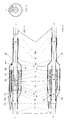
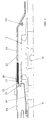
- Kabelverbindung zum Verbinden von Netzkabeln (1, 2), wobei jedes Kabel einen Leiter (4, 5) hat, welcher aufeinanderfolgend von einer ersten Isolierschicht (6A, 7A), einer halbleitenden Schicht (6B, 7B), einem metallischen Schirm (8, 9) und einer zweiten Isolierschicht (10, 11) umgeben ist,
wobei die Kabelverbindung einen Anschlußkörper (3) umfaßt, welcher Verbindungsmittel (12) umfaßt, die dazu ausgelegt sind, blankgemachte Abschnitte von Leiterenden miteinander zu verbinden, sowie erste Isoliermittel (13), die dazu ausgelegt sind, diese Verbindungsmittel (12) zu umgeben,
wobei die Verbindung ferner ein metallisches Element (14; 15, 16) umfaßt, welches eine Abschirmung über dem Anschlußkörper (3) bildet, sowie zweite Isoliermittel (23, 24), welche das metallische Element überdecken und dazu ausgelegt ist, Endabschnitte der zweiten Isolierschicht (10, 11) der Netzkabel zu überdecken,
wobei das metallische Element wenigstens zwei Teile (14; 15, 16) hat, die durch eine Abschirmungsunterbrechung (17) elektrisch getrennt sind und jeweils mit einem Anschluß (19A, 22) ausgestattet sind, die dazu ausgelegt sind, mit dem metallischen Schirm (8, 9) eines bestimmten der Netzkabel (1, 2) elektrisch gekuppelt zu werden, dadurch gekennzeichnet, daß wenigstens einer der Anschlüsse (19A, 22) ein interner Anschluß (19A) ist, welcher an der inneren Seite des metallischen Elementes (14; 15, 16) angeordnet und dazu ausgelegt ist, mit einem Ende eines isolierten Leiters (20) verbunden zu werden, welcher innerhalb des metallischen Elementes angeordnet ist und dessen anderes Ende (19B) dazu ausgelegt ist, sich nach außerhalb des metallischen Elementes zu erstrecken. - Kabelverbindung nach Anspruch 1, dadurch gekennzeichnet, daß das metallische Element (14; 15, 16) die Form eines Rohres hat, mit einem zylindrischen Teil, welcher an jedem Ende des Anschlußkörpers (3) verengt ist, wobei die Abschirmungsunterbrechung (17) in diesem zylindrischen Teil vorgesehen ist, und
daß der interne Anschluß (19A) mit einem ersten Teil (14) des metallischen Elementes verbunden und zwischen einem ersten verengten Ende des Rohres und einem entsprechenden ersten Ende des Anschlußkörpers angeordnet ist. - Kabelverbindung nach Anspruch 2, dadurch gekennzeichnet, daß der mit dem zweiten Teil (15, 16) des metallischen Elementes (14; 15, 16) verbundene Anschluß ein externer Anschluß (22) ist, welcher an dem zweiten verengten Ende (16) des Rohres angeordnet ist,
daß die ersten (14) und zweiten (15, 16) Teile des metallischen Elementes zusammen eine wasserdichte Box bilden, die den Anschlußkörper (3) umgibt, und
daß das andere Ende (19B) des isolierten Leiters (20) sich durch eine Öffnung (21) hindurch erstreckt, die in dem zweiten Teil (15, 16) des Elementes in der Nähe des externen Anschlusses (22) vorgesehen ist. - Kabelverbindung nach Anspruch 3, dadurch gekennzeichnet, daß der zweite Teil (15, 16) des metallischen Elementes (14; 15, 16) das zweite verengte Ende (16) sowie einen Abschnitt (15) des zylindrischen Teils des Rohres zwischen dem zweiten verengten Ende und der Abschirmungsunterbrechung (17) umfaßt, und
daß das zweite verengte Ende (16) den externen Anschluß (22) und die Öffnung (21) aufweist. - Kabelverbindung nach Anspruch 4, dadurch gekennzeichnet, daß der Abschnitt (15) des zylindrischen Teils des Rohres, welcher zu dem zweiten Teil (15, 16) des metallischen Elementes (14; 15, 16) gehört, die Abschirmungsunterbrechung (17) und der erste Teil (14) des metallischen Elementes einschließlich des verbleibenden zylindrischen Teils des Rohres und das erste verengte Ende starr zusammengebaut sind, und
daß das zweite verengte Ende (16) mechanisch mit dieser starren Anordnung verbunden wird. - Kabelverbindung nach Anspruch 5, dadurch gekennzeichnet, daß ein vorfabrizierter Isolator (18) an der Abschirmungsunterbrechung (17) vorgesehen ist, und daß die einander gegenüberliegenden Enden der beiden zylindrischen Teile des Rohres mechanisch mit dem Isolator verbunden sind.
- Kabelverbindung nach Anspruch 1, dadurch gekennzeichnet, daß eine Schicht aus einem Material (25) mit einer relativ hohen Dielektrizitätskonstante den isolierten Leiter (20) in dem Bereich der Abschirmungsunterbrechung (17) umgibt.
- Kabelverbindung nach Anspruch 3, dadurch gekennzeichnet, daß das andere Ende (19B) des isolierten Leiters (20) mit dem zentralen Leiter eines koaxialen Kabels verbunden ist, von welchem die Abschirmung mit dem externen Anschluß (22) verbunden ist, wobei das koaxiale Kabel für Erdungs- oder cross-bonding-Verbindungen verwendet wird.
- Kabelverbindung nach Anspruch 3, dadurch gekennzeichnet, daß die wasserdichte Box mit Glaskügelchen gefüllt ist.
- Kabelverbindung nach Anspruch 3, dadurch gekennzeichnet, daß die zweiten Isoliermittel (23, 24) eine Polyesterbox (24) umfassen, die mit Harz gefüllt ist.
Priority Applications (4)
| Application Number | Priority Date | Filing Date | Title |
|---|---|---|---|
| DE69711055T DE69711055T2 (de) | 1997-11-28 | 1997-11-28 | Kabelverbindung mit Erdungsverbindung und/oder Schirmauskreuzung für Energiekabl |
| EP97402882A EP0920101B1 (de) | 1997-11-28 | 1997-11-28 | Kabelverbindung mit Erdungsverbindung und/oder Schirmauskreuzung für Energiekabl |
| JP10308888A JPH11205987A (ja) | 1997-11-28 | 1998-10-29 | 電力ケーブルのための接地接続および/または網クロスボンドを備えるケーブル継手 |
| US09/195,436 US6040527A (en) | 1997-11-28 | 1998-11-18 | Cable joint with grounding connection and/or screen cross-bonding for power cables |
Applications Claiming Priority (1)
| Application Number | Priority Date | Filing Date | Title |
|---|---|---|---|
| EP97402882A EP0920101B1 (de) | 1997-11-28 | 1997-11-28 | Kabelverbindung mit Erdungsverbindung und/oder Schirmauskreuzung für Energiekabl |
Publications (2)
| Publication Number | Publication Date |
|---|---|
| EP0920101A1 EP0920101A1 (de) | 1999-06-02 |
| EP0920101B1 true EP0920101B1 (de) | 2002-03-13 |
Family
ID=8229915
Family Applications (1)
| Application Number | Title | Priority Date | Filing Date |
|---|---|---|---|
| EP97402882A Expired - Lifetime EP0920101B1 (de) | 1997-11-28 | 1997-11-28 | Kabelverbindung mit Erdungsverbindung und/oder Schirmauskreuzung für Energiekabl |
Country Status (4)
| Country | Link |
|---|---|
| US (1) | US6040527A (de) |
| EP (1) | EP0920101B1 (de) |
| JP (1) | JPH11205987A (de) |
| DE (1) | DE69711055T2 (de) |
Families Citing this family (20)
| Publication number | Priority date | Publication date | Assignee | Title |
|---|---|---|---|---|
| KR101135143B1 (ko) | 2004-03-01 | 2012-04-16 | 후루카와 덴키 고교 가부시키가이샤 | 케이블 접속구조 |
| AU2005339512B2 (en) | 2005-12-28 | 2011-06-16 | Prysmian Cavi E Sistemi Energia S.R.L. | Joining method and related junction for electric cables, tubular covering sleeve for electric-cable junctions and process for manufacturing the same |
| JP2007259623A (ja) * | 2006-03-24 | 2007-10-04 | Three M Innovative Properties Co | 電線用モールドスぺーサ、電線用接続キット、電線の製造方法及び電線 |
| EP2088656A1 (de) * | 2008-02-08 | 2009-08-12 | ABB Technology AG | Kabelverbindungsanordnung |
| EP2088657A1 (de) | 2008-02-08 | 2009-08-12 | ABB Technology AG | Verfahren zur Herstellung eines Kabelgehäuses, Kabelgehäuse und damit ausgestattete Kabelverbindungsanordnung |
| FR2977396B1 (fr) * | 2011-07-01 | 2013-07-05 | Nexans | Ligne electrique munie de jonctions a arrets d'ecrans |
| JP5776123B2 (ja) * | 2012-08-20 | 2015-09-09 | 株式会社ビスキャス | 電力ケーブルの接続構造および絶縁部材 |
| CN103986112B (zh) * | 2013-02-12 | 2017-03-01 | 株式会社维世佳 | 电力电缆的连接构造和绝缘部件 |
| JP5761535B2 (ja) * | 2013-02-12 | 2015-08-12 | 株式会社ビスキャス | 電力ケーブルの接続構造および絶縁部材 |
| JP6282870B2 (ja) * | 2014-01-30 | 2018-02-21 | 昭和電線ケーブルシステム株式会社 | 保護管及び電力ケーブルの中間接続部 |
| TWI574285B (zh) * | 2014-03-14 | 2017-03-11 | 吳俊宏 | 續接式防水電纜結構、續接式防水電源模組以及防水端子套組總成 |
| US9504195B2 (en) | 2014-05-16 | 2016-11-22 | Tyco Electronics Corporation | Cover assemblies, kits and methods for covering electrical cables and connections |
| JP2016010202A (ja) * | 2014-06-23 | 2016-01-18 | 株式会社ビスキャス | 電力ケーブル接続部および防食カバー |
| CN104868435A (zh) * | 2015-06-02 | 2015-08-26 | 张维秀 | 一种电缆与信号线缆转接的密封接头及其制作方法 |
| EP3104463B1 (de) * | 2015-06-12 | 2020-11-11 | Siemens Aktiengesellschaft | Unterwasserverbinder |
| WO2018098166A1 (en) | 2016-11-22 | 2018-05-31 | Te Connectivity Corporation | Cover assemblies for cables and electrical connections and pre-expanded units and methods including same |
| CN107632203B (zh) * | 2017-08-14 | 2019-09-03 | 国网湖南省电力公司 | 一种考虑大地影响的大型地网接地阻抗测试方法 |
| US12407152B2 (en) * | 2019-05-01 | 2025-09-02 | Brugg Kabel Ag | Repair and replacement of high voltage cables and joints |
| CN112670911B (zh) * | 2020-12-23 | 2023-01-03 | 长园电力技术有限公司 | 铝护套电缆与金属管的连接方法和连接结构 |
| CN115832734A (zh) * | 2022-12-26 | 2023-03-21 | 江苏中天科技电缆附件有限公司 | 具有多功能接地方式的电缆接头及电缆接头的接地方法 |
Family Cites Families (9)
| Publication number | Priority date | Publication date | Assignee | Title |
|---|---|---|---|---|
| US28837A (en) * | 1860-06-26 | Fog-alarm | ||
| GB1059270A (en) * | 1964-10-23 | 1967-02-15 | British Insulated Callenders | Improvements in joints for electric cables |
| USRE28837E (en) | 1971-12-30 | 1976-06-01 | Amerace Corporation | Shielding tape grounding device for high voltage cables |
| US4032205A (en) * | 1976-09-10 | 1977-06-28 | Rte Corporation | Adaptor for a high voltage cable |
| US4234756A (en) * | 1979-03-29 | 1980-11-18 | Reliable Electric Company | Preterminated block system and method of installing same |
| FI69943C (fi) * | 1979-07-10 | 1986-05-26 | Sumitomo Electric Industries | Foerfarande foer bildande av en foerbindning foer en polyolefinisolerad elektrisk ledning eller kabel och vaermekrympande slang foer genomfoerande av foerfarandet |
| FR2593335B1 (fr) * | 1986-01-22 | 1988-07-22 | Pirelli Treficable | Dispositif pour relier deux cables electriques isoles comportant des moyens perfectionnes de protection exterieure de la jonction |
| DE4102114C2 (de) * | 1991-01-25 | 1994-01-20 | Rheydt Kabelwerk Ag | Verfahren zum zyklischen Auskreuzen von Kabelmänteln |
| DE9415782U1 (de) * | 1994-09-23 | 1996-01-25 | Siemens AG, 80333 München | Kunststoffisolierte Hochspannungskabelanlage mit Schirmtrennstellen |
-
1997
- 1997-11-28 DE DE69711055T patent/DE69711055T2/de not_active Expired - Fee Related
- 1997-11-28 EP EP97402882A patent/EP0920101B1/de not_active Expired - Lifetime
-
1998
- 1998-10-29 JP JP10308888A patent/JPH11205987A/ja not_active Withdrawn
- 1998-11-18 US US09/195,436 patent/US6040527A/en not_active Expired - Fee Related
Also Published As
| Publication number | Publication date |
|---|---|
| EP0920101A1 (de) | 1999-06-02 |
| DE69711055T2 (de) | 2002-09-12 |
| US6040527A (en) | 2000-03-21 |
| DE69711055D1 (de) | 2002-04-18 |
| JPH11205987A (ja) | 1999-07-30 |
Similar Documents
| Publication | Publication Date | Title |
|---|---|---|
| EP0920101B1 (de) | Kabelverbindung mit Erdungsverbindung und/oder Schirmauskreuzung für Energiekabl | |
| EP0920102B1 (de) | Aussenschutz mit Abschirmungsunterbrechung für Hochspannungskabelverbindung | |
| US3307137A (en) | Conductor termination | |
| KR100394929B1 (ko) | 전력케이블접속구조체 | |
| US20070137881A1 (en) | Terminal structure of multiphase superconducting cable | |
| JP3769046B2 (ja) | 電気ケーブル端子 | |
| CN102474090B (zh) | 用于海底电缆的接头 | |
| US4424410A (en) | Splice connector with shield break | |
| US4518819A (en) | Clamp assembly for power cables | |
| US6172304B1 (en) | Device for providing leakproof protection to a splice in a high voltage cable | |
| US3792191A (en) | Enclosure for conductor of electrical transmission system | |
| JPH07193965A (ja) | 電力ケーブル接続箱 | |
| EP2088657A1 (de) | Verfahren zur Herstellung eines Kabelgehäuses, Kabelgehäuse und damit ausgestattete Kabelverbindungsanordnung | |
| US4638112A (en) | Stop joint for interconnecting two electrical cables of different types | |
| JP3601991B2 (ja) | 接地用終端接続部 | |
| CN113659494A (zh) | 10-35kV熔接式交联电缆终端的制备工艺 | |
| KR940002352Y1 (ko) | 가교폴리에틸렌 절연케이블용 프리몰드 접속함 | |
| JPH09224325A (ja) | 電力ケーブル接続部 | |
| JP3006333B2 (ja) | 光ファイバユニット内蔵形電力ケーブル用終端接続部 | |
| JPH04255682A (ja) | シールドケーブル及びその端末構造 | |
| US20250372992A1 (en) | Wet-type outdoor cable termination | |
| EP2710683B1 (de) | Kabelschuh mit geerdeter oberfläche und isolierter abschirmung | |
| SU1191954A1 (ru) | Сухой стержневой трансформатор | |
| JPH11205989A (ja) | 電力ケーブルの外部終端装置 | |
| CA1094181A (en) | Electrical cable joint casing |
Legal Events
| Date | Code | Title | Description |
|---|---|---|---|
| PUAI | Public reference made under article 153(3) epc to a published international application that has entered the european phase |
Free format text: ORIGINAL CODE: 0009012 |
|
| AK | Designated contracting states |
Kind code of ref document: A1 Designated state(s): BE DE ES FR GB IT SE |
|
| AX | Request for extension of the european patent |
Free format text: AL;LT;LV;MK;RO;SI |
|
| 17P | Request for examination filed |
Effective date: 19991202 |
|
| AKX | Designation fees paid |
Free format text: BE DE ES FR GB IT SE |
|
| 17Q | First examination report despatched |
Effective date: 20000317 |
|
| GRAG | Despatch of communication of intention to grant |
Free format text: ORIGINAL CODE: EPIDOS AGRA |
|
| GRAH | Despatch of communication of intention to grant a patent |
Free format text: ORIGINAL CODE: EPIDOS IGRA |
|
| RAP1 | Party data changed (applicant data changed or rights of an application transferred) |
Owner name: NEXANS |
|
| GRAH | Despatch of communication of intention to grant a patent |
Free format text: ORIGINAL CODE: EPIDOS IGRA |
|
| REG | Reference to a national code |
Ref country code: GB Ref legal event code: IF02 |
|
| GRAA | (expected) grant |
Free format text: ORIGINAL CODE: 0009210 |
|
| AK | Designated contracting states |
Kind code of ref document: B1 Designated state(s): BE DE ES FR GB IT SE Kind code of ref document: B1 Designated state(s): BE CH DE FR IT LI NL SE |
|
| REF | Corresponds to: |
Ref document number: 69711055 Country of ref document: DE Date of ref document: 20020418 |
|
| REG | Reference to a national code |
Ref country code: CH Ref legal event code: NV Representative=s name: CABINET ROLAND NITHARDT CONSEILS EN PROPRIETE INDU Ref country code: CH Ref legal event code: EP |
|
| RBV | Designated contracting states (corrected) |
Designated state(s): BE CH DE FR IT LI NL SE |
|
| ET | Fr: translation filed | ||
| PGFP | Annual fee paid to national office [announced via postgrant information from national office to epo] |
Ref country code: SE Payment date: 20021106 Year of fee payment: 6 |
|
| PGFP | Annual fee paid to national office [announced via postgrant information from national office to epo] |
Ref country code: FR Payment date: 20021108 Year of fee payment: 6 |
|
| PGFP | Annual fee paid to national office [announced via postgrant information from national office to epo] |
Ref country code: DE Payment date: 20021128 Year of fee payment: 6 |
|
| PGFP | Annual fee paid to national office [announced via postgrant information from national office to epo] |
Ref country code: NL Payment date: 20021129 Year of fee payment: 6 Ref country code: CH Payment date: 20021129 Year of fee payment: 6 |
|
| PLBE | No opposition filed within time limit |
Free format text: ORIGINAL CODE: 0009261 |
|
| STAA | Information on the status of an ep patent application or granted ep patent |
Free format text: STATUS: NO OPPOSITION FILED WITHIN TIME LIMIT |
|
| PGFP | Annual fee paid to national office [announced via postgrant information from national office to epo] |
Ref country code: BE Payment date: 20030121 Year of fee payment: 6 |
|
| 26N | No opposition filed |
Effective date: 20021216 |
|
| PG25 | Lapsed in a contracting state [announced via postgrant information from national office to epo] |
Ref country code: SE Free format text: LAPSE BECAUSE OF NON-PAYMENT OF DUE FEES Effective date: 20031129 |
|
| PG25 | Lapsed in a contracting state [announced via postgrant information from national office to epo] |
Ref country code: LI Free format text: LAPSE BECAUSE OF NON-PAYMENT OF DUE FEES Effective date: 20031130 Ref country code: CH Free format text: LAPSE BECAUSE OF NON-PAYMENT OF DUE FEES Effective date: 20031130 Ref country code: BE Free format text: LAPSE BECAUSE OF NON-PAYMENT OF DUE FEES Effective date: 20031130 |
|
| BERE | Be: lapsed |
Owner name: *NEXANS Effective date: 20031130 |
|
| PG25 | Lapsed in a contracting state [announced via postgrant information from national office to epo] |
Ref country code: NL Free format text: LAPSE BECAUSE OF NON-PAYMENT OF DUE FEES Effective date: 20040601 |
|
| PG25 | Lapsed in a contracting state [announced via postgrant information from national office to epo] |
Ref country code: DE Free format text: LAPSE BECAUSE OF NON-PAYMENT OF DUE FEES Effective date: 20040602 |
|
| EUG | Se: european patent has lapsed | ||
| REG | Reference to a national code |
Ref country code: CH Ref legal event code: PL |
|
| PG25 | Lapsed in a contracting state [announced via postgrant information from national office to epo] |
Ref country code: FR Free format text: LAPSE BECAUSE OF NON-PAYMENT OF DUE FEES Effective date: 20040730 |
|
| NLV4 | Nl: lapsed or anulled due to non-payment of the annual fee |
Effective date: 20040601 |
|
| REG | Reference to a national code |
Ref country code: FR Ref legal event code: ST |
|
| PG25 | Lapsed in a contracting state [announced via postgrant information from national office to epo] |
Ref country code: IT Free format text: LAPSE BECAUSE OF NON-PAYMENT OF DUE FEES;WARNING: LAPSES OF ITALIAN PATENTS WITH EFFECTIVE DATE BEFORE 2007 MAY HAVE OCCURRED AT ANY TIME BEFORE 2007. THE CORRECT EFFECTIVE DATE MAY BE DIFFERENT FROM THE ONE RECORDED. Effective date: 20051128 |