EP0920116A2 - Wechselrichteranordnung zum Antrieb eines elektrischen Motors und Filteranordnung zum Gebrauch in der Wechselrichteranordnung - Google Patents
Wechselrichteranordnung zum Antrieb eines elektrischen Motors und Filteranordnung zum Gebrauch in der Wechselrichteranordnung Download PDFInfo
- Publication number
- EP0920116A2 EP0920116A2 EP98119311A EP98119311A EP0920116A2 EP 0920116 A2 EP0920116 A2 EP 0920116A2 EP 98119311 A EP98119311 A EP 98119311A EP 98119311 A EP98119311 A EP 98119311A EP 0920116 A2 EP0920116 A2 EP 0920116A2
- Authority
- EP
- European Patent Office
- Prior art keywords
- current
- circuit
- core
- canceling
- filter
- Prior art date
- Legal status (The legal status is an assumption and is not a legal conclusion. Google has not performed a legal analysis and makes no representation as to the accuracy of the status listed.)
- Granted
Links
Images


Classifications
-
- H—ELECTRICITY
- H02—GENERATION; CONVERSION OR DISTRIBUTION OF ELECTRIC POWER
- H02M—APPARATUS FOR CONVERSION BETWEEN AC AND AC, BETWEEN AC AND DC, OR BETWEEN DC AND DC, AND FOR USE WITH MAINS OR SIMILAR POWER SUPPLY SYSTEMS; CONVERSION OF DC OR AC INPUT POWER INTO SURGE OUTPUT POWER; CONTROL OR REGULATION THEREOF
- H02M5/00—Conversion of AC power input into AC power output, e.g. for change of voltage, for change of frequency, for change of number of phases
- H02M5/40—Conversion of AC power input into AC power output, e.g. for change of voltage, for change of frequency, for change of number of phases with intermediate conversion into DC
- H02M5/42—Conversion of AC power input into AC power output, e.g. for change of voltage, for change of frequency, for change of number of phases with intermediate conversion into DC by static converters
- H02M5/44—Conversion of AC power input into AC power output, e.g. for change of voltage, for change of frequency, for change of number of phases with intermediate conversion into DC by static converters using discharge tubes or semiconductor devices to convert the intermediate DC into AC
- H02M5/453—Conversion of AC power input into AC power output, e.g. for change of voltage, for change of frequency, for change of number of phases with intermediate conversion into DC by static converters using discharge tubes or semiconductor devices to convert the intermediate DC into AC using devices of a triode or transistor type requiring continuous application of a control signal
- H02M5/458—Conversion of AC power input into AC power output, e.g. for change of voltage, for change of frequency, for change of number of phases with intermediate conversion into DC by static converters using discharge tubes or semiconductor devices to convert the intermediate DC into AC using devices of a triode or transistor type requiring continuous application of a control signal using semiconductor devices only
-
- H—ELECTRICITY
- H02—GENERATION; CONVERSION OR DISTRIBUTION OF ELECTRIC POWER
- H02M—APPARATUS FOR CONVERSION BETWEEN AC AND AC, BETWEEN AC AND DC, OR BETWEEN DC AND DC, AND FOR USE WITH MAINS OR SIMILAR POWER SUPPLY SYSTEMS; CONVERSION OF DC OR AC INPUT POWER INTO SURGE OUTPUT POWER; CONTROL OR REGULATION THEREOF
- H02M1/00—Details of apparatus for conversion
- H02M1/12—Arrangements for reducing harmonics from AC input or output
-
- H—ELECTRICITY
- H02—GENERATION; CONVERSION OR DISTRIBUTION OF ELECTRIC POWER
- H02J—ELECTRIC POWER NETWORKS; CIRCUIT ARRANGEMENTS OR SYSTEMS FOR SUPPLYING OR DISTRIBUTING ELECTRIC POWER; SYSTEMS FOR STORING ELECTRIC ENERGY
- H02J3/00—Circuit arrangements for AC mains or AC distribution networks
- H02J3/01—Arrangements for reducing harmonics or ripples
-
- H—ELECTRICITY
- H02—GENERATION; CONVERSION OR DISTRIBUTION OF ELECTRIC POWER
- H02M—APPARATUS FOR CONVERSION BETWEEN AC AND AC, BETWEEN AC AND DC, OR BETWEEN DC AND DC, AND FOR USE WITH MAINS OR SIMILAR POWER SUPPLY SYSTEMS; CONVERSION OF DC OR AC INPUT POWER INTO SURGE OUTPUT POWER; CONTROL OR REGULATION THEREOF
- H02M7/00—Conversion of AC power input into DC power output; Conversion of DC power input into AC power output
- H02M7/42—Conversion of DC power input into AC power output without possibility of reversal
- H02M7/44—Conversion of DC power input into AC power output without possibility of reversal by static converters
- H02M7/48—Conversion of DC power input into AC power output without possibility of reversal by static converters using discharge tubes with control electrode or semiconductor devices with control electrode
-
- H—ELECTRICITY
- H01—ELECTRIC ELEMENTS
- H01F—MAGNETS; INDUCTANCES; TRANSFORMERS; SELECTION OF MATERIALS FOR THEIR MAGNETIC PROPERTIES
- H01F17/00—Fixed inductances of the signal type
- H01F17/04—Fixed inductances of the signal type with magnetic core
- H01F17/06—Fixed inductances of the signal type with magnetic core with core substantially closed in itself, e.g. toroid
- H01F17/062—Toroidal core with turns of coil around it
-
- H—ELECTRICITY
- H02—GENERATION; CONVERSION OR DISTRIBUTION OF ELECTRIC POWER
- H02M—APPARATUS FOR CONVERSION BETWEEN AC AND AC, BETWEEN AC AND DC, OR BETWEEN DC AND DC, AND FOR USE WITH MAINS OR SIMILAR POWER SUPPLY SYSTEMS; CONVERSION OF DC OR AC INPUT POWER INTO SURGE OUTPUT POWER; CONTROL OR REGULATION THEREOF
- H02M1/00—Details of apparatus for conversion
- H02M1/0003—Details of control, feedback or regulation circuits
- H02M1/0009—Devices or circuits for detecting current in a converter
-
- Y—GENERAL TAGGING OF NEW TECHNOLOGICAL DEVELOPMENTS; GENERAL TAGGING OF CROSS-SECTIONAL TECHNOLOGIES SPANNING OVER SEVERAL SECTIONS OF THE IPC; TECHNICAL SUBJECTS COVERED BY FORMER USPC CROSS-REFERENCE ART COLLECTIONS [XRACs] AND DIGESTS
- Y02—TECHNOLOGIES OR APPLICATIONS FOR MITIGATION OR ADAPTATION AGAINST CLIMATE CHANGE
- Y02E—REDUCTION OF GREENHOUSE GAS [GHG] EMISSIONS, RELATED TO ENERGY GENERATION, TRANSMISSION OR DISTRIBUTION
- Y02E40/00—Technologies for an efficient electrical power generation, transmission or distribution
- Y02E40/40—Arrangements for reducing harmonics
Definitions
- the present invention relates to an inverter apparatus for use in a refrigerating apparatus having a compressor, and also to a filter apparatus for use in the inverter apparatus.
- An refrigerating apparatus such as an air conditioner or a refrigerator comprises a compressor and an inverter apparatus for driving the electric motor incorporated in the compressor.
- the inverter apparatus has a DC circuit and a switching circuit.
- the DC circuit converts the voltage of a commercially available AC power supply to a DC voltage.
- the switching circuit performs switching on the DC voltage, converting the DC voltage to a high-frequency voltage.
- the high-frequency voltage is supplied, as drive power, to the electric motor incorporated in the compressor.
- the compressor comprises a closed case, in which the electric motor is provided.
- the closed case is made of metal (e.g., iron).
- the case is connected to the earth terminal for the sake of safety.
- the electric motor is a brush-less DC motor having three phase-windings.
- Electrostatic capacitance (generally known as "stray capacitance") exists between the closed case (i.e., the earth terminal) and the phase-windings.
- stray capacitance exists between the closed case (i.e., the earth terminal) and the phase-windings.
- the high-frequency leak current dielectrically flows toward the commercially available power supply.
- the leak current may adversely influence the control of the inverter apparatus and may cause errors in other electric appliance, the breaker and the like.
- choke coils may be provided on the conduction lines that connect the output of the inverter apparatus to the electric motor.
- the switching frequency of the inverter apparatus may be lowered for the same purpose. If choke coils are so provided, however, it still difficult to reduce the high-frequency leak current sufficiently when the switching frequency of the inverter apparatus increases. If the switching frequency of the inverter apparatus, it will be impossible to enhance the performance of the compressor, resulting in an inadequate refrigerating efficiency.
- the object of the invention is to provide an inverter apparatus for use in a refrigerating apparatus having a compressor, which has a switching circuit, which can be manufactured at low cost and which can yet reliably reduce the leak current from the compressor even if the switching frequency of the switching circuit is high.
- an inverter apparatus for supplying drive power to a motor which has a plurality of phase-windings and which is contained in a closed metal case of a compressor, which is connected to the ground.
- the inverter apparatus comprising: a DC circuit for converting a voltage of an AC power supply to a DC voltage; a switching circuit for switching an output voltage of the DC circuit, thereby to convert the same to a high-frequency voltage, and for applying the high-frequency voltage as drive power for the motor; a noise-removing filter provided on lines connecting the DC circuit and the switching circuit, the filter having coils; a current-detecting coil provided in the filter, for detecting a leak current flowing from the phase-windings of the motor to the ground through the closed case, and characterized in the coil is made of a wire thinner than wires forming the coils of the filter and/or that the coil has less turns than each of the coils of the filter; and a current-canceling circuit for generating a current similar in waveform to the leak current detected
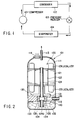
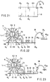
- FIG. 1 shows the refrigeration cycle relating to the first embodiment.
- the refrigeration cycle comprises a compressor 101, a condenser 102, a pressure reducer 103, and an evaporator 104.
- the pressure reducer 103 is, for example, an expansion value or a capillary tube.
- the compressor 101, condenser 102, device 103 and evaporator 104 are connected by pipes, constituting a loop.
- the refrigeration cycle thus formed is filled with refrigerant.
- the compressor 101 comprises a closed case 111 made of metal.
- a suction pipe 112 is connected to the lower end part of the case 111.
- a discharge pipe 113 and a terminal 114 are connected to the top of the case 111.
- the compressor 101 further comprises a motor 120 and a compressing section 130, which are contained in the closed case 111.
- the motor 120 is provided to drive the compressing section 130.
- the motor 120 is a brush-less DC motor comprising a stator 121 and a rotor 122. Three phase-windings 123r, 123s and 123t are wound around the stator 121.
- the rotor 122 is comprises a number of steel discs and permanent magnets (for example, four magnets). The steel discs are piled one upon another, forming a cylinder which has an axial hole.
- a shaft 124 extends through the axial hole of the cylinder composed of the steel discs.
- the permanent magnets are embedded in the cylinder, surrounding the shaft 124.
- phase-windings 123r, 123s and 123 sequentially and repeatedly, thus accomplishing commutation.
- the windings 123r, 123s and 123t generate magnetic fields, one after another.
- the magnetic fields interact with the magnetic fields of the permanent magnets in the rotor 122, generating a torque in the rotor 122.
- the compressing section 130 has a main bearing 131, a sub-bearing 132, and a cylinder 133.
- the main bearing 131 and the sub-bearing 132 support the shaft 124.
- the cylinder 133 is clamped between the bearings 131 and 132 and loosely mounted on the shaft 124.
- the shaft 124 has an eccentric part 124a, which is contained in the cylinder 133.
- a roller 134 is mounted on the eccentric part 124a.
- a compression chamber 135 is defined between the outer circumferential surface of the roller 134 and the inner circumferential surface of the cylinder 133.
- the compression chamber 135 communicates with an inlet port 136, which in turn communicates with the inlet pipe 112.
- the cylinder 133 has a discharge port (not shown), which connects the compression chamber 135 to the upper part of the closed case 111.
- Lubricant oil 140 is contained in the bottom of the closed case 111.
- the oil 140 performs two function. First, it lubricates the mechanical components of the compression section 130. Second, it cools the compression section 130.
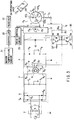
- An inverter apparatus shown in FIG. 3 is provided to supply drive power to the motor 120.
- the inverter apparatus comprises a first filter apparatus (low-pass filter, or generally known as "line filter") 2, a DC circuit 5a, a switching circuit 13, a current-canceling circuit 30, and a current-detecting coil L 3 .
- the first filter apparatus 2 is connected to a commercially available power supply 1.
- the DC circuit 5a is connected to the output of the first filter apparatus 2.
- the first filter apparatus 2 comprises two choke coils 3 and two capacitors 4.
- the first filter apparatus 2 prevents a high-frequency noise from propagating from the DC circuit 5a to the power supply 1.
- the DC circuit 5a comprises a rectifier circuit 6, a second filter apparatus (low-pass filter) 8, and a smoothing capacitor 10.
- the rectifier circuit 6 has four diodes 6a connected, forming a bridge.
- the second filter apparatus 8 is connected to the output of the rectifier circuit 6, for removing noise.
- the smoothing capacitor 10 is connected to the output of the second filter apparatus 8.
- the DC circuit 5a converts the AC voltage applied from the power supply 1 to a DC voltage.
- the output of the DC circuit 5a is connected to the switching circuit 13, which will be described later.
- the second filter apparatus 8 comprises a ferrite core 9 and a pair of coils L 1 and L 2 .
- the coils L 1 and L 2 are copper synchronous windings, both wound around the ferrite core 9.
- the coils L 1 and L 2 are provided on DC lines P and N, respectively.
- the lines P and N connect the rectifier circuit 6 to the switching circuit 13.
- a noise current flows from the noise source through the coil L 1 , which generates a magnetic field.
- the noise current flows back through the coil L 2 , which generates a magnetic field.
- the switching circuit 13 has a plurality of switching elements such as power transistors.
- the power transistors perform switching on the DC voltage applied from the DC circuit 5a, thereby converting the DC voltage to a three-phase high-frequency voltage.
- the three-phase high-frequency voltage is output from the switching circuit 13.
- the output voltage of the switching circuit 13 is applied to the phase-windings 123r, 123s and 123 of the motor 120 through conduction lines 15r, 15s and 15t, respectively.
- the closed case 111 which contains the motor 120, is connected to an earth terminal E for the sake of safety.
- the phase-windings 123r, 123s and 123t are connected to a common point Po for star connection.
- An electrostatic capacitance C (also known as "stray capacitance") exists between the closed case (i.e., the earth terminal E) and each of the phase-windings 123r, 123s and 123t.
- a common mode voltage is generated between the earth terminal E and the common point Po of the phase-windings 123r, 123s and 123t, through the electrostatic capacitances C.
- a common mode current is generated from the common mode voltage and flows from the phase-windings 123r, 123s and 123t to the earth terminal E through the capacitances C.
- the common mode current is equivalent to a high-frequency leak current I 1 .
- the current-detecting coil L 3 is designed to detect the common mode current (i.e., the high-frequency leak current I 1 ).
- the coil L 3 is characterized in at least one of the following respects. First, it is made of wire thinner than the wires forming the coils L 1 and coil L 2 of the second filter apparatus 8. Second, it has less turns than the coils L 1 and coil L 2 of the second filter apparatus 8.
- the current-detecting coil L 3 has a predetermined inductance of, for example, 100 ⁇ H or more.
- the current-canceling circuit 30 comprises an amplifier circuit, two diodes 34, a capacitor 35, and two resistors 36 and 37.
- the amplifier circuit has an NPN transistor 32 and a PNP transistor 33 and is designed to amplify the output voltage of the current-detecting coil L 3 .
- the amplifier circuit is driven to operate by the output voltage of the DC circuit 5a.
- the diodes 34 are provided for preventing a reverse electromotive force.
- the first diode 34 is connected between the collector and emitter of the transistor 32.
- the second diode 34 is connected between the collector and emitter of the transistor 33.
- the capacitor 35 is provided for removing a DC component and has a capacitance equal to the electrostatic capacitances C that exists between the closed case 111 and each of the phase-windings 123r, 123s and 123t.
- the resistors 36 and 37 are used to remove noises.
- the amplifier circuit generates a current I 2 having a waveform similar to that of the high-frequency leak current I 1 .
- the current I 2 is output through the capacitor 35 and the resistor 36, thereby to cancel out the high-frequency leak current I 1 .
- the current-canceling circuit 30 has an output terminal 30a, which is connected to the earth terminal E.
- the DC circuit 5a has grounding capacitors 7a and 7b for removing noises.
- the capacitors 7a and 7b are connected in series between DC lines P and N which connect the rectifier circuit 6 and the second filter apparatus 8.
- the DC circuit 5a further has grounding capacitors 11a and 11b for removing noises. These capacitors 11a and 11b are connected in series between DC lines P and N which connect the second filter apparatus 8 and the switching circuit 13.
- the controller 20 is provided for controlling the air conditioner.
- An indoor temperature sensor 21, a receiver 22 and a drive control circuit 23 are connected to the controller 20.
- the indoor temperature sensor 21 detects the temperature Ta in the room which is to be air-conditioned by the air conditioner.
- the receiver 22 receives the infrared rays emitted from an operating unit 24 of remote-control type.
- the operating unit transmits data for setting operating conditions into the air conditioner, in the form of infrared rays.
- the drive control circuit 23 turns on and off the power transistors of the switching circuit 13.
- the circuit 23 controls the on-drive cycle and off-drive cycle of the power transistors, i.e., the circuit 23 controls the switching frequency of each power transistor.
- the circuit 23 also performs control (PWM control) on the on-period (on-off duty) of each power transistor.
- the operating unit 24 is operated, setting a desired indoor temperature Ts.
- the unit 24 is further operated, thereby starting the air conditioner.
- the switching circuit 13 is driven.
- the output of the switching circuit 13 drives the motor 120.
- the difference ⁇ T between the indoor temperature Ta detected by the indoor temperature sensor 21 and the desired temperature Ts set by the operating unit 24 is obtained.
- the switching frequency of the switching circuit 13 is controlled in accordance with the difference ⁇ T.
- the rotational sped of the motor 120 changes.
- the change in the rotational speed of the motor 120 results in a change in the performance of the compressor 101.
- the switching circuit 13 stops operating, and the motor 120 stops, interrupting the operation of the compressor 101.
- a common mode voltage is generated between the earth terminal E and the common point Po of the phase-windings 123r, 123s and 123t, through the electrostatic capacitances C. Due to the common mode voltage, a high-frequency leak current I 1 of several megahertz flows from the phase-windings 123r, 123s and 123t to the earth terminal E through the electrostatic capacitances C.
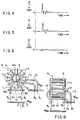
- the common mode current I 1 has such a waveform as is shown in FIG. 4.
- the high-frequency leak current I 1 dielectrically flows toward the commercially available power supply 1.
- the leak current may adversely influence the control of the inverter apparatus and may cause errors in other electric appliance, the breaker and the like.
- the leak current is made to flow into the DC circuit 5a.
- the current-detecting coil L 3 detects a current which is proportional to the high-frequency leak current I 1 .
- the output voltage of the current-detecting coil L 3 is amplified the transistors 32 and 33, providing a canceling current I 2 having a waveform similar to that of the high-frequency leak current I 1 , as is illustrated in FIG. 5.
- the canceling current I 2 has such polarity that it tends to flow from the earth terminal E toward the current-canceling circuit 30. Due to the specific polarity and waveform of the canceling current I 2 , the high-frequency leak current I 1 is canceled as if absorbed into the current-canceling circuit 30. Hence, the current I 3 flowing to the earth terminal E comes to have such a low-level waveform as is shown in FIG. 6.
- the high-frequency leak current I 1 is detected, the canceling current I 2 , is generated whose waveform is similar to that of the leak current I 1 , and the leak current I 1 is forcibly canceled with the canceling current I 2 .
- the high-frequency leak current I 1 can be reduced reliably even if the switching frequency of the switching circuit 13 is high. It follows that the switching frequency of the circuit 13 can be increased as much as desired, without adversely influencing the control of the inverter apparatus and without causing errors in other electric appliance, the breaker and the like.
- the performance of the compressor 101 can be enhanced sufficiently, enabling the air conditioner to acquire high operating efficiency.
- the refrigerant filled in the refrigeration cycle may be HFC refrigerant which has a small electrically insulating property and the lubricating oil used in the compressor 101 may be ester oil (or ether oil) which has a large dielectric constant. If so, the high-frequency leak current I 1 is likely to increase. Nevertheless, the inverter apparatus can reliably reduce the leak current I 1 which has increased due to the use of HFC refrigerant and ester oil (or ether oil).
- the current-detecting coil L 3 is made of wire thinner than the wires forming the coils L 1 and coil L 2 of the second filter apparatus 8, its use scarcely increases the manufacturing cost of the inverter apparatus.
- the coil L 3 has less turns than the coils L 1 and coil L 2 . This also serves to minimize the manufacturing cost of the inverter apparatus.
- the second filter apparatus 8 may fail to remove noises as much as is desired.
- the coil L 3 can detects the high-frequency leak current I 1 without impairing the noise-removing function of the second filter apparatus 8, because it has an inductance of, for example, 100 ⁇ H or more, as indicated above.
- the current-canceling circuit 30 outputs the canceling current I 2 , through the capacitor 35 which has a capacitance equal to the electrostatic capacitance between the closed case 111 and the phase-windings 123r, 123s and 123t and which is provided for removing a DC component. Passed through the capacitor 35, the canceling current I 2 has a waveform very similar to the waveform of the high-frequency leak current I 1 . Hence, the current I 2 cancels out the high-frequency leak current I 1 efficiently.
- the noise-removing resistor 36 is connected to the capacitor 35. Therefore, the circuit 30 cooperate with the second filter apparatus 8, removing noises with high efficiency.
- the capacitors 7a and 7b are connected in series between DC lines P and N connecting the rectifier circuit 6 and the switching circuit 13 and are located on the input side of the second filter apparatus 8. Further, as mentioned above, too, the capacitors 11a and 11b are connected in series between DC lines P and N and are located on the output side of the second filter apparatus 8. The capacitors 7a, 7b, 11a and 11b also help increase the efficiency of removing noises.
- FIGS. 7, 8 and 9 are a front view, a side view and a plan view of the apparatus 8, respectively.
- FIG. 10 is an equivalent circuit diagram of the apparatus 8.
- connection terminals 8a and 8b are connected to the ends of the coil L 1 , respectively, and are provided on the DC line P.
- Connection terminals 8c and 8d are connected to the ends of the coil L 2 , respectively, and are provided on the DC line N.
- the current-detecting coil L 3 for detecting the high-frequency leak current (an unbalanced current) I 1 has one turn or more turns.
- Connection terminals 8e and 8f are connected to the ends of the current-detecting coil L 3 , respectively.
- the connection terminals 8e and 8f are also connected to the current-canceling circuit 30.
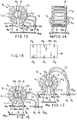
- the ferrite core 9 of the second filter apparatus 8 is ring-shaped.
- the core 9 stand upright on the circuit board (PC board) 40pc of the DC circuit 5a. More precisely, the core 9 is secured to the circuit board by means of a core stand 10.
- the core stand 10 comprises a base 10H and two holding parts 10I and 10J.
- the lower holding part 10I extends vertically from the base 10H.
- the upper holding part 10J is connected to the top of the lower holding part 10I and extends upwards therefrom.
- the lower holding part 10I holds the lower part of the ferrite core 9, while the upper holding part 10J holds the upper part of the ferrite core 9.
- the base 10H of the core stand 10 is shaped like a plate. As FIG. 9 shows, the base 10H has four U-notches 10a to 10d, which allow passage of the rod-shaped connection terminals 8a to 8d, respectively.
- FIG. 11 shows the inverter apparatus incorporated in an inverter apparatus 8 according to the second embodiment.
- This filter apparatus is characterized in three respects.
- connection terminals 8e and 8f are male-type ones.
- the circuit board 30pc of a DC circuit has female-type connectors 30e and 30f.
- the connection terminals 8e and 8f are inserted in the connectors 30e and 30f, respectively. It is therefore easy to incorporate a current-detecting coil L 3 into the filter apparatus 8 and removed the coil L 3 therefrom.
- the second embodiment is identical to the first embodiment in structure.
- FIG. 12 shows the filter apparatus 8 provided in an inverter apparatus according to the third embodiment.
- the apparatus 8 has connection terminals 8e and 8f of female-type. These connectors 8e and 8f are secured to the top of the holding part 10J of a core stand 10. Signal lines 39 are soldered at one end to the circuit board 30pc of a DC circuit, and at the other end to female-type connectors 30e and 30f. The connectors 30e and 30f are inserted in the connection terminals 8e and 8f.
- the third embodiment is identical to the first embodiment in structure.
- FIG. 13 is a front view of the filter apparatus 8 provided in an inverter apparatus according to the fourth embodiment.
- FIG. 14 is a side view of the filter apparatus 8
- FIG. 15 is a plan view of the base 10H of the core stand 10 provided in the filter apparatus 8.
- the filter apparatus 8 has rod-shaped connection terminals 8e and 8f, which are connected to the ends of the current-detecting coil L 3 , respectively.
- the base 10H of the core stand 10 has a part extending sideways and is therefore longer than its counterpart used in the second and third embodiments.
- the extending part of the base 10H has U-notches 10e and 10f, in which the rod-shaped connection terminals 8e and 8f are held. (The notches 10e and 10f may be replaced by through holes.)
- the filter apparatus 8 of the fourth embodiment has six connection terminals in all, i.e., the terminals 8a to 8f. Having six connection terminals, the filter apparatus 8 can be easily incorporated into the inverter apparatus.
- the fourth embodiment is identical to the first embodiment in structure.
- FIG. 16 illustrates the filter apparatus 8 provided in an inverter apparatus according to the fifth embodiment.
- an annular holding member 10x is set in the center space of an annular ferrite core 9.
- the holding member 10x holds a current-detecting coil L 3 , spaced from coils L 1 and L 2 .
- the member 10x is a part of a core stand 10.
- the current-detecting coil L 3 is completely insulated from the coils L 1 and L 2 .
- the coil L 3 can therefore detects noises and a high-frequency leak current I 1 , with high reliability.
- the fifth embodiment is identical to the first embodiment in structure.
- FIG. 17 shows the filter apparatus 8 provided in an inverter apparatus according to the sixth embodiment.
- a Y-shaped holding member 10y is set in the center space of an annular ferrite core 9.
- the holding member 10y holds a current-detecting coil L 3 , spaced from coils L 1 and L 2 .
- the member 10y is a part of a core stand 10.
- the current-detecting coil L 3 is completely insulated from the coils L 1 and L 2 .
- the coil L 3 can therefore detects noises and a high-frequency leak current I 1 , with high reliability.
- the sixth embodiment is identical to the first embodiment in structure.
- the means for insulating the current-detecting coil L 3 from the coils L 1 and L 2 is not limited to the holding members 10x and 10y.
- the current-detecting coil L 3 may be made of a wire in an insulting sheath.
- partitions may be provided to insulate the coil L 3 from the coils L 1 and L 2 .
- a plate having holes may be provided, guiding the current-detecting coil L 3 through the holes and spacing the same away from the coils L 1 and L 2 .
- FIG. 18 shows the filter apparatus 8 provided in an inverter apparatus according to the eighth embodiment.
- a current-detecting coil L 3 is provided, corresponding to the lower holding part 10I of a core stand 10.
- the lower holding part 10I connects the base 10H of the core stand 10 to a lower part of a ferrite core 9.
- the part 10I also holds the ferrite core 9 upright.
- the base 10H has U-notches 10e and 10f in the vicinity of the lower holding part 10I.
- Rod-shaped connection terminals 8e and 8f are held in the U-notches 10e and 10f, respectively.
- a holding member 10Z in the form of an inverted Y is provided, holding the current-detecting coil L 3 and spacing the same from the coils L 1 and L 2 .
- the current-detecting coil L 3 can be made shorter. Further, the base 10H of the core stand 10 can be made as small as is desired, though the current-detecting coil L 3 is secured to it.
- the eighth embodiment is identical to the first embodiment in structure.
- FIG. 19 shows the filter apparatus 8 provided in an inverter apparatus according to the ninth embodiment.
- the base 10H of a core stand 10 has a part extending sideways.
- Transistors 32 and 33 and capacitor 35, which constitute a current-canceling circuit 30, are attached to the extending part of the base 10H.
- the current-canceling circuit 30 is integral with the filter apparatus 8.
- the filter apparatus 8 has a current/noise-canceling section and can be handled as a single part.
- the ninth embodiment is identical to the first embodiment in structure.
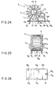
- FIG. 20 shows the filter apparatus 8 provided in an inverter apparatus according to the tenth embodiment.
- FIG. 21 is a plan view of the base 10H of the core stand 10 provided in the filter apparatus 8.
- the base 10H of a core stand 10 has a part extending sideways.
- Transistors 32 and 33 and capacitor 35, which constitute a current-canceling circuit 30, are attached to the extending part of the base 10H.
- the current-canceling circuit 30 is integral with the filter apparatus 8. It is therefore possible to connect the output terminal 30a of a canceling circuit 30 to a circuit board 40pc, by soldering a signal line 38 to the circuit board 40pc.
- the tenth embodiment is identical to the first embodiment in structure.
- FIG. 22 shows the filter apparatus 8 provided in an inverter apparatus according to the eleventh embodiment.
- the output terminal 30a of a canceling circuit 30 to one end of the signal line 38.
- the signal line 38 has a connector 38a at the other end.
- the connector 38a is connected to a circuit board 40pc.
- the output terminal 30a is electrically connected to the circuit board 40pc.
- FIG. 23 illustrates the filter apparatus 8 provided in an inverter apparatus according to the eleventh embodiment.
- a signal line 38 is connected at one end to a circuit board 40pc.
- the signal line 38 has a connector 38a at the other end.
- the connector 38a is connected to the output terminal 30a of a canceling circuit 30.
- the output terminal 30a is electrically connected to the circuit board 40pc.
- FIG. 24 shows the filter apparatus 8 incorporated in an inverter apparatus according to a thirteenth embodiment of the invention.
- FIG. 25 is a side view of the filter apparatus
- FIG. 26 is a plan view of the base of the core stand provided in the filter apparatus.
- the base 10H of a core stand 10 has a part extending sideways.
- a chip 300 is mounted on the extending part of the base 10H.
- the extending part has a U-notch 10g, in which a rod-shaped output terminal 30a is inserted and held.
- the filter apparatus has five terminals, i.e., one output terminal 30a and four connection terminals 8a, 8b, 8c and 8d.
- the thirteenth embodiment is identical to the first embodiment in structure.
- the filter apparatus 8 is provided on a single-phase line. Nonetheless, the filter apparatus 8 can operate in the same way if it is provided on a line of three or more phases.
- FIG. 27 shows the control circuit incorporating an inverter apparatus according to the fourteenth embodiment.
- the inverter apparatus and a drive control circuit 23 are contained in a metal housing 16.
- the output terminal 30a of the current-canceling circuit 30 is connected to the metal housing 16.
- the housing 16 is mounted on the outdoor unit of an air conditioner.
- the fourteenth embodiment is identical to the first embodiment in structure.
- the fourteen embodiment serves to facilitate the assembling of the air conditioner. Furthermore, the fourteenth embodiment achieves the same advantages as the first embodiment.
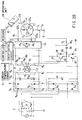
- FIG. 28 shows the control circuit incorporating an inverter apparatus according to the fifteenth embodiment.
- a DC circuit 5b is connected by the filter apparatus 2 to a commercially available power supply 1.
- the DC circuit 5b comprises a rectifier circuit 6 and a smoothing capacitor 14.
- the rectifier circuit 6 (second rectifier circuit) has four diodes 6a connected, forming a bridge.
- the smoothing capacitor 14 is connected to the output of the rectifier circuit 6.
- the DC circuit 5b converts the AC voltage applied from the power supply 1 to a DC voltage that is lower than the output voltage of a DC circuit 5a.
- the output voltage of the DC circuit 5b is applied, as an operation voltage, to a current-canceling circuit 30.
- the DC circuit 5a comprises a pair of smoothing capacitors 12a and 12b.
- the smoothing capacitors 12a and 12b are connected to the output of the rectifier circuit 6.
- the fifteenth embodiment is identical to the first embodiment in structure.
- the fifteenth embodiment can operate correctly, without breaking down the transistors 32 and 33 incorporated in the current-canceling circuit 30, even if the transistors 32 and 33 have relatively low withstand voltage.
- the fourteenth embodiment achieves the same advantages as the first embodiment.
Landscapes
- Engineering & Computer Science (AREA)
- Power Engineering (AREA)
- Inverter Devices (AREA)
- Control Of Ac Motors In General (AREA)
Applications Claiming Priority (6)
| Application Number | Priority Date | Filing Date | Title |
|---|---|---|---|
| JP28367097A JPH11122910A (ja) | 1997-10-16 | 1997-10-16 | フィルタ装置 |
| JP28367097 | 1997-10-16 | ||
| JP283670/97 | 1997-10-16 | ||
| JP355433/97 | 1997-12-24 | ||
| JP35543397 | 1997-12-24 | ||
| JP9355433A JPH11187671A (ja) | 1997-12-24 | 1997-12-24 | インバータ装置および冷凍サイクル装置 |
Publications (3)
| Publication Number | Publication Date |
|---|---|
| EP0920116A2 true EP0920116A2 (de) | 1999-06-02 |
| EP0920116A3 EP0920116A3 (de) | 2001-04-04 |
| EP0920116B1 EP0920116B1 (de) | 2003-04-16 |
Family
ID=26555133
Family Applications (1)
| Application Number | Title | Priority Date | Filing Date |
|---|---|---|---|
| EP98119311A Expired - Lifetime EP0920116B1 (de) | 1997-10-16 | 1998-10-13 | Wechselrichteranordnung zum Antrieb eines elektrischen Motors und Filteranordnung zum Gebrauch in der Wechselrichteranordnung |
Country Status (7)
| Country | Link |
|---|---|
| US (1) | US6151228A (de) |
| EP (1) | EP0920116B1 (de) |
| KR (1) | KR100305250B1 (de) |
| CN (1) | CN1087882C (de) |
| DE (1) | DE69813470T2 (de) |
| ID (1) | ID21096A (de) |
| TW (1) | TW407394B (de) |
Cited By (11)
| Publication number | Priority date | Publication date | Assignee | Title |
|---|---|---|---|---|
| EP0986165A3 (de) * | 1998-09-08 | 2001-01-17 | Kabushiki Kaisha Toshiba | Stromwandlungssystem |
| EP1220432A3 (de) * | 2000-12-19 | 2003-01-29 | Fuji Electric Co., Ltd. | Geräuschverminderungsvorrichtung für elektrische Leistungswandlungsvorrichtung |
| EP1143602A3 (de) * | 2000-03-28 | 2003-11-26 | International Rectifier Corporation | Aktives Filter zur Gleichtaktstromreduzierung |
| EP1388199A4 (de) * | 2001-05-17 | 2006-12-27 | Int Rectifier Corp | Aktives gleichtaktfilter, das in eine a-c-leitung geschaltet ist |
| CN100364201C (zh) * | 2004-01-13 | 2008-01-23 | 三洋电机株式会社 | 系统连接用逆变器装置 |
| EP1122877A3 (de) * | 1999-12-13 | 2008-12-24 | Sew-Eurodrive GmbH & Co. KG | System zur Fernbedienung |
| EP2192678A4 (de) * | 2007-09-21 | 2011-03-02 | Mitsubishi Electric Corp | Stromumrichteinrichtung für ein elektrofahrzeug |
| DE102013204638A1 (de) * | 2012-12-12 | 2014-06-12 | Panasonic Industrial Devices Europe Gmbh | Vorrichtung zur Erfassung von Fehlerströmen |
| FR3004029A1 (fr) * | 2013-03-29 | 2014-10-03 | Somfy Sas | Actionneur electrique ou electromecanique, dispositif de domotique comprenant un tel actionneur et ensemble de motorisation comprenant un tel actionneur |
| CN107078657A (zh) * | 2014-09-26 | 2017-08-18 | 大金工业株式会社 | 功率转换装置 |
| EP4412069A4 (de) * | 2021-09-30 | 2025-01-22 | Daikin Industries, Ltd. | Leistungsumwandlungsvorrichtung und kühlvorrichtung |
Families Citing this family (35)
| Publication number | Priority date | Publication date | Assignee | Title |
|---|---|---|---|---|
| US6987372B1 (en) | 2001-04-11 | 2006-01-17 | Rockwell Automation Technologies, Inc. | Integrated DC link choke and method for suppressing common-mode voltage in a motor drive |
| US7132812B1 (en) | 2001-04-11 | 2006-11-07 | Rockwell Automation Technologies, Inc. | Integrated DC link choke and method for suppressing common-mode voltage in a motor drive |
| US6617814B1 (en) | 2001-04-11 | 2003-09-09 | Rockwell Automation Technologies, Inc. | Integrated DC link choke and method for suppressing common-mode voltage in a motor drive |
| WO2003058791A2 (en) * | 2002-01-07 | 2003-07-17 | International Rectifier Corporation | Active emi filter with feed forward cancellation |
| CN100448162C (zh) * | 2002-01-07 | 2008-12-31 | 国际整流器公司 | 具有前馈补偿的有源电磁干扰滤波器 |
| JP4206668B2 (ja) * | 2002-01-08 | 2009-01-14 | ダイキン工業株式会社 | ノイズフィルタ、室外機及び空気調和機 |
| JP2003219691A (ja) * | 2002-01-17 | 2003-07-31 | Meidensha Corp | 永久磁石式同期モータの駆動システム及びその試験方法 |
| US6819076B2 (en) * | 2002-05-02 | 2004-11-16 | International Rectifier Corporation | Active EMI filter with magnetoresistive sensor for common mode noise current |
| US6788558B2 (en) * | 2002-09-19 | 2004-09-07 | International Rectifier Corporation | Passive common mode filter and method for operating a passive common mode filter |
| JP4110976B2 (ja) * | 2003-01-17 | 2008-07-02 | 松下電工株式会社 | スイッチング電源装置 |
| JP4003741B2 (ja) * | 2003-12-04 | 2007-11-07 | 松下電器産業株式会社 | モータ制御装置 |
| FR2880739B1 (fr) * | 2005-01-07 | 2009-04-24 | Technofan Sa | Etage de redressement d'un courant triphase. |
| US7529106B2 (en) * | 2005-08-12 | 2009-05-05 | Kabushiki Kaisha Toyota Jidoshokki | Voltage monitoring device and inverter device |
| JP2007116861A (ja) * | 2005-10-24 | 2007-05-10 | Hitachi Industrial Equipment Systems Co Ltd | 電力変換装置 |
| FR2898441B1 (fr) * | 2006-03-13 | 2008-04-25 | Schneider Toshiba Inverter | Procede de parametrage d'un convertisseur et convertisseur mettant en oeuvre le procede |
| US20080297275A1 (en) * | 2007-06-01 | 2008-12-04 | Robert Keith Hollenbeck | Dual configuration filter circuit |
| AU2008280932B8 (en) * | 2007-07-24 | 2011-02-24 | Panasonic Electric Works Co., Ltd. | Charging monitor |
| MX2010004420A (es) | 2007-10-24 | 2010-05-05 | Afl Telecommunications Llc | Filtro para red electrica de ca y sistema de suministro de energia. |
| JP2009213066A (ja) * | 2008-03-06 | 2009-09-17 | Nec Corp | フィルタ回路及びその制御方法 |
| FR2930093A1 (fr) * | 2008-04-10 | 2009-10-16 | Somfy Sas | Dispositif de type emetteur et/ou recepteur de signaux radioelectriques |
| JP5138551B2 (ja) * | 2008-11-06 | 2013-02-06 | サンデン株式会社 | インバータ一体型電動圧縮機 |
| CN102342010B (zh) * | 2009-03-05 | 2014-12-03 | 三菱电机株式会社 | 漏电流降低装置 |
| CN104081640A (zh) * | 2012-01-27 | 2014-10-01 | 三菱电机株式会社 | 高频电流降低装置 |
| JP5201276B1 (ja) * | 2012-01-27 | 2013-06-05 | ダイキン工業株式会社 | 電力変換回路 |
| JP5316656B2 (ja) | 2012-01-27 | 2013-10-16 | ダイキン工業株式会社 | 電力変換回路 |
| JP5974761B2 (ja) * | 2012-09-18 | 2016-08-23 | 株式会社豊田自動織機 | 車載用電動圧縮機 |
| KR101711706B1 (ko) * | 2014-11-20 | 2017-03-02 | 주식회사 엘지화학 | 공통 모드 노이즈 시뮬레이터 |
| EP3243083A1 (de) * | 2015-01-08 | 2017-11-15 | Sondex Wireline Limited | Empfindlicher gleichstrom-ungleichgewichtsdetektor und kalibrierverfahren |
| JP6525676B2 (ja) * | 2015-03-31 | 2019-06-05 | ヴィオニア日信ブレーキシステムジャパン株式会社 | ブレーキ制御装置用チョークコイル |
| JP6168211B2 (ja) * | 2015-12-28 | 2017-07-26 | ダイキン工業株式会社 | 電力変換装置 |
| JP6673468B2 (ja) | 2016-03-31 | 2020-03-25 | 株式会社豊田自動織機 | 車載用電動圧縮機 |
| DE112017001684T5 (de) * | 2016-03-31 | 2018-12-13 | Kabushiki Kaisha Toyota Jidoshokki | Fahrzeugseitiger elektrischer Kompressor |
| JP6690498B2 (ja) * | 2016-10-31 | 2020-04-28 | 株式会社豊田自動織機 | 車載用電動圧縮機 |
| JP7081554B2 (ja) * | 2019-03-29 | 2022-06-07 | 株式会社豊田自動織機 | 電動圧縮機 |
| US12273025B2 (en) * | 2020-05-20 | 2025-04-08 | Ngai Kit Franki Poon | Power supply apparatus |
Family Cites Families (13)
| Publication number | Priority date | Publication date | Assignee | Title |
|---|---|---|---|---|
| JPS6059978A (ja) * | 1983-09-12 | 1985-04-06 | Toshiba Corp | 空気調和機 |
| US4888675A (en) * | 1987-08-26 | 1989-12-19 | Harris Corporation | Switching power supply filter |
| US4833377A (en) * | 1987-12-28 | 1989-05-23 | Beta Raven Inc. | Current leakage reduction circuit |
| EP0661453B1 (de) * | 1993-12-28 | 2003-04-23 | Sanyo Electric Co. Ltd | Klimaanlage und zugehöriger Schaltkreis für den Inverter |
| JP3579075B2 (ja) * | 1994-01-12 | 2004-10-20 | 三洋電機株式会社 | 空気調和装置 |
| JP3567027B2 (ja) * | 1995-09-14 | 2004-09-15 | Fdk株式会社 | 巻線素子及びその組立方法 |
| JP3331881B2 (ja) * | 1995-12-21 | 2002-10-07 | 三菱電機株式会社 | インバータ装置、圧縮機 |
| JP3044650B2 (ja) * | 1996-03-27 | 2000-05-22 | 勲 高橋 | 電力変換装置のノイズ低減装置 |
| JPH1042585A (ja) * | 1996-05-21 | 1998-02-13 | Toshiba Corp | 冷凍サイクル装置のインバータ装置および冷凍サイクル装置 |
| KR100199507B1 (en) * | 1996-12-13 | 1999-06-15 | Korea Electro Technology Res Inst | A device to improving quality for ac power source |
| JPH11122910A (ja) * | 1997-10-16 | 1999-04-30 | Toshiba Corp | フィルタ装置 |
| US5905642A (en) * | 1997-11-11 | 1999-05-18 | Robicon Corporation | Apparatus and method to reduce common mode voltage from current source drives |
| US5936856A (en) * | 1998-02-13 | 1999-08-10 | Baldor Electric Companh | Method and apparatus for active common-mode voltage compensation in induction motor systems |
-
1998
- 1998-09-30 TW TW087116273A patent/TW407394B/zh not_active IP Right Cessation
- 1998-10-13 EP EP98119311A patent/EP0920116B1/de not_active Expired - Lifetime
- 1998-10-13 DE DE69813470T patent/DE69813470T2/de not_active Expired - Fee Related
- 1998-10-16 ID IDP981372A patent/ID21096A/id unknown
- 1998-10-16 US US09/173,558 patent/US6151228A/en not_active Expired - Fee Related
- 1998-10-16 KR KR1019980043767A patent/KR100305250B1/ko not_active Expired - Fee Related
- 1998-10-16 CN CN98121374A patent/CN1087882C/zh not_active Expired - Fee Related
Cited By (18)
| Publication number | Priority date | Publication date | Assignee | Title |
|---|---|---|---|---|
| EP0986165A3 (de) * | 1998-09-08 | 2001-01-17 | Kabushiki Kaisha Toshiba | Stromwandlungssystem |
| EP1122877A3 (de) * | 1999-12-13 | 2008-12-24 | Sew-Eurodrive GmbH & Co. KG | System zur Fernbedienung |
| EP1143602A3 (de) * | 2000-03-28 | 2003-11-26 | International Rectifier Corporation | Aktives Filter zur Gleichtaktstromreduzierung |
| US6794929B2 (en) | 2000-03-28 | 2004-09-21 | International Rectifier Corporation | Active filter for reduction of common mode current |
| US7583136B2 (en) | 2000-03-28 | 2009-09-01 | International Rectifier Corporation | Active filter for reduction of common mode current |
| US7385438B2 (en) | 2000-03-28 | 2008-06-10 | International Rectifier Corporation | Active filter for reduction of common mode current |
| EP1220432A3 (de) * | 2000-12-19 | 2003-01-29 | Fuji Electric Co., Ltd. | Geräuschverminderungsvorrichtung für elektrische Leistungswandlungsvorrichtung |
| EP1388199A4 (de) * | 2001-05-17 | 2006-12-27 | Int Rectifier Corp | Aktives gleichtaktfilter, das in eine a-c-leitung geschaltet ist |
| CN100364201C (zh) * | 2004-01-13 | 2008-01-23 | 三洋电机株式会社 | 系统连接用逆变器装置 |
| EP2192678A4 (de) * | 2007-09-21 | 2011-03-02 | Mitsubishi Electric Corp | Stromumrichteinrichtung für ein elektrofahrzeug |
| US8345453B2 (en) | 2007-09-21 | 2013-01-01 | Mitsubishi Electric Corporation | Power conversion apparatus for electric vehicle |
| DE102013204638A1 (de) * | 2012-12-12 | 2014-06-12 | Panasonic Industrial Devices Europe Gmbh | Vorrichtung zur Erfassung von Fehlerströmen |
| DE102013204638B4 (de) | 2012-12-12 | 2019-04-04 | Panasonic Industrial Devices Europe Gmbh | Vorrichtung zur Erfassung von Fehlerströmen |
| FR3004029A1 (fr) * | 2013-03-29 | 2014-10-03 | Somfy Sas | Actionneur electrique ou electromecanique, dispositif de domotique comprenant un tel actionneur et ensemble de motorisation comprenant un tel actionneur |
| CN107078657A (zh) * | 2014-09-26 | 2017-08-18 | 大金工业株式会社 | 功率转换装置 |
| EP3176940A4 (de) * | 2014-09-26 | 2018-04-11 | Daikin Industries, Ltd. | Stromwandlungsvorrichtung |
| CN107078657B (zh) * | 2014-09-26 | 2019-08-20 | 大金工业株式会社 | 功率转换装置 |
| EP4412069A4 (de) * | 2021-09-30 | 2025-01-22 | Daikin Industries, Ltd. | Leistungsumwandlungsvorrichtung und kühlvorrichtung |
Also Published As
| Publication number | Publication date |
|---|---|
| CN1087882C (zh) | 2002-07-17 |
| KR100305250B1 (ko) | 2001-09-24 |
| DE69813470T2 (de) | 2004-04-01 |
| ID21096A (id) | 1999-04-22 |
| TW407394B (en) | 2000-10-01 |
| EP0920116B1 (de) | 2003-04-16 |
| EP0920116A3 (de) | 2001-04-04 |
| CN1215246A (zh) | 1999-04-28 |
| DE69813470D1 (de) | 2003-05-22 |
| US6151228A (en) | 2000-11-21 |
| KR19990037206A (ko) | 1999-05-25 |
Similar Documents
| Publication | Publication Date | Title |
|---|---|---|
| US6151228A (en) | Filter apparatus for use in an inverter apparatus | |
| CA2091500C (en) | Integral motor and control | |
| US6998736B2 (en) | Apparatus and method for controlling driving of linear motor | |
| US9071090B2 (en) | Motor and electric device including the same | |
| EP0809346B1 (de) | Wechselrichter zur Versorgung eines bürstenlosen Gleichstrommotors mit Leistung | |
| KR20170094353A (ko) | 전자적 양립 가능한 필터 | |
| JP2004104895A (ja) | 圧縮機駆動装置及び冷凍空調装置 | |
| JP2002325353A (ja) | インバータ保護装置 | |
| KR101979452B1 (ko) | Emi 노이즈 저감을 위한 액티브 노이즈 필터 | |
| JP7315862B2 (ja) | 電力変換装置及び冷凍装置 | |
| EP1721384A1 (de) | System und verfahren zur vergrösserung der ausgangspferdestärke und effizienz in einem motor | |
| KR20040096767A (ko) | 전원 시스템 및 공기 조화 장치 | |
| US10978981B2 (en) | Drive apparatus for electric motor and air conditioner | |
| JPH11122910A (ja) | フィルタ装置 | |
| KR100196531B1 (ko) | 공기조화기의 인버터장치 및 공기조화기 | |
| JPH11187671A (ja) | インバータ装置および冷凍サイクル装置 | |
| JP3667962B2 (ja) | 漏洩電流抑制回路 | |
| WO2020255249A1 (ja) | 電力変換装置、冷凍サイクル装置および空気調和装置 | |
| KR20190076669A (ko) | 전력변환장치 및 이를 구비하는 공기조화기 | |
| JP2001045767A (ja) | インバータ装置 | |
| KR20190016378A (ko) | 전력변환장치 및 이를 구비하는 홈 어플라이언스 | |
| JPH0759257A (ja) | 冷媒圧縮機用モータの漏電防止装置 | |
| KR102260614B1 (ko) | 공기조화기 | |
| JP2004245227A (ja) | 圧縮機 | |
| JP2023172700A (ja) | インバータ装置及びそれを備えた電動圧縮機 |
Legal Events
| Date | Code | Title | Description |
|---|---|---|---|
| PUAI | Public reference made under article 153(3) epc to a published international application that has entered the european phase |
Free format text: ORIGINAL CODE: 0009012 |
|
| 17P | Request for examination filed |
Effective date: 19981110 |
|
| AK | Designated contracting states |
Kind code of ref document: A2 Designated state(s): DE ES FR GB IT |
|
| AX | Request for extension of the european patent |
Free format text: AL;LT;LV;MK;RO;SI |
|
| PUAL | Search report despatched |
Free format text: ORIGINAL CODE: 0009013 |
|
| AK | Designated contracting states |
Kind code of ref document: A3 Designated state(s): AT BE CH CY DE DK ES FI FR GB GR IE IT LI LU MC NL PT SE |
|
| AX | Request for extension of the european patent |
Free format text: AL;LT;LV;MK;RO;SI |
|
| RIC1 | Information provided on ipc code assigned before grant |
Free format text: 7H 02M 5/458 A, 7H 02M 1/12 B |
|
| 17Q | First examination report despatched |
Effective date: 20010810 |
|
| AKX | Designation fees paid |
Free format text: DE ES FR GB IT |
|
| GRAH | Despatch of communication of intention to grant a patent |
Free format text: ORIGINAL CODE: EPIDOS IGRA |
|
| GRAH | Despatch of communication of intention to grant a patent |
Free format text: ORIGINAL CODE: EPIDOS IGRA |
|
| GRAA | (expected) grant |
Free format text: ORIGINAL CODE: 0009210 |
|
| AK | Designated contracting states |
Designated state(s): DE ES FR GB IT |
|
| PG25 | Lapsed in a contracting state [announced via postgrant information from national office to epo] |
Ref country code: IT Free format text: LAPSE BECAUSE OF FAILURE TO SUBMIT A TRANSLATION OF THE DESCRIPTION OR TO PAY THE FEE WITHIN THE PRESCRIBED TIME-LIMIT;WARNING: LAPSES OF ITALIAN PATENTS WITH EFFECTIVE DATE BEFORE 2007 MAY HAVE OCCURRED AT ANY TIME BEFORE 2007. THE CORRECT EFFECTIVE DATE MAY BE DIFFERENT FROM THE ONE RECORDED. Effective date: 20030416 Ref country code: FR Free format text: LAPSE BECAUSE OF FAILURE TO SUBMIT A TRANSLATION OF THE DESCRIPTION OR TO PAY THE FEE WITHIN THE PRESCRIBED TIME-LIMIT Effective date: 20030416 |
|
| REG | Reference to a national code |
Ref country code: GB Ref legal event code: FG4D |
|
| REF | Corresponds to: |
Ref document number: 69813470 Country of ref document: DE Date of ref document: 20030522 Kind code of ref document: P |
|
| PG25 | Lapsed in a contracting state [announced via postgrant information from national office to epo] |
Ref country code: ES Free format text: LAPSE BECAUSE OF FAILURE TO SUBMIT A TRANSLATION OF THE DESCRIPTION OR TO PAY THE FEE WITHIN THE PRESCRIBED TIME-LIMIT Effective date: 20031030 |
|
| PLBE | No opposition filed within time limit |
Free format text: ORIGINAL CODE: 0009261 |
|
| STAA | Information on the status of an ep patent application or granted ep patent |
Free format text: STATUS: NO OPPOSITION FILED WITHIN TIME LIMIT |
|
| 26N | No opposition filed |
Effective date: 20040119 |
|
| EN | Fr: translation not filed | ||
| PGFP | Annual fee paid to national office [announced via postgrant information from national office to epo] |
Ref country code: DE Payment date: 20061005 Year of fee payment: 9 |
|
| PGFP | Annual fee paid to national office [announced via postgrant information from national office to epo] |
Ref country code: GB Payment date: 20061011 Year of fee payment: 9 |
|
| REG | Reference to a national code |
Ref country code: GB Ref legal event code: 746 Effective date: 20070318 |
|
| GBPC | Gb: european patent ceased through non-payment of renewal fee |
Effective date: 20071013 |
|
| PG25 | Lapsed in a contracting state [announced via postgrant information from national office to epo] |
Ref country code: DE Free format text: LAPSE BECAUSE OF NON-PAYMENT OF DUE FEES Effective date: 20080501 |
|
| PG25 | Lapsed in a contracting state [announced via postgrant information from national office to epo] |
Ref country code: GB Free format text: LAPSE BECAUSE OF NON-PAYMENT OF DUE FEES Effective date: 20071013 |