EP0920126B1 - Verfahren und Vorrichtung zum adaptiven Regeln des Verstärkungsfaktors eines Verstärkers - Google Patents
Verfahren und Vorrichtung zum adaptiven Regeln des Verstärkungsfaktors eines Verstärkers Download PDFInfo
- Publication number
- EP0920126B1 EP0920126B1 EP98120169A EP98120169A EP0920126B1 EP 0920126 B1 EP0920126 B1 EP 0920126B1 EP 98120169 A EP98120169 A EP 98120169A EP 98120169 A EP98120169 A EP 98120169A EP 0920126 B1 EP0920126 B1 EP 0920126B1
- Authority
- EP
- European Patent Office
- Prior art keywords
- amplifier
- monitoring
- amplification
- operating state
- gain
- Prior art date
- Legal status (The legal status is an assumption and is not a legal conclusion. Google has not performed a legal analysis and makes no representation as to the accuracy of the status listed.)
- Expired - Lifetime
Links
- 238000000034 method Methods 0.000 title claims abstract description 11
- 238000012544 monitoring process Methods 0.000 claims abstract description 34
- 238000011156 evaluation Methods 0.000 claims abstract description 27
- 230000003321 amplification Effects 0.000 claims description 27
- 238000003199 nucleic acid amplification method Methods 0.000 claims description 27
- 230000003044 adaptive effect Effects 0.000 claims description 19
- 230000002829 reductive effect Effects 0.000 claims description 13
- 238000012546 transfer Methods 0.000 claims description 7
- 230000000737 periodic effect Effects 0.000 claims description 6
- 230000010355 oscillation Effects 0.000 claims description 4
- 230000001105 regulatory effect Effects 0.000 claims description 4
- 230000008859 change Effects 0.000 claims description 3
- 230000009467 reduction Effects 0.000 claims description 3
- 230000033228 biological regulation Effects 0.000 claims description 2
- 230000008034 disappearance Effects 0.000 claims description 2
- 230000003534 oscillatory effect Effects 0.000 claims 2
- 230000003247 decreasing effect Effects 0.000 abstract description 2
- 238000010586 diagram Methods 0.000 description 4
- 230000005540 biological transmission Effects 0.000 description 3
- 230000007423 decrease Effects 0.000 description 3
- 230000002787 reinforcement Effects 0.000 description 3
- 230000004044 response Effects 0.000 description 3
- 230000008054 signal transmission Effects 0.000 description 3
- 230000015556 catabolic process Effects 0.000 description 2
- 230000001276 controlling effect Effects 0.000 description 2
- 230000008878 coupling Effects 0.000 description 2
- 238000010168 coupling process Methods 0.000 description 2
- 238000005859 coupling reaction Methods 0.000 description 2
- 238000006731 degradation reaction Methods 0.000 description 2
- 230000001419 dependent effect Effects 0.000 description 2
- 238000011161 development Methods 0.000 description 2
- 230000018109 developmental process Effects 0.000 description 2
- 230000005855 radiation Effects 0.000 description 2
- 238000004891 communication Methods 0.000 description 1
- 238000012937 correction Methods 0.000 description 1
- 238000013016 damping Methods 0.000 description 1
- 238000001514 detection method Methods 0.000 description 1
- 230000006866 deterioration Effects 0.000 description 1
- 230000007613 environmental effect Effects 0.000 description 1
- 230000000977 initiatory effect Effects 0.000 description 1
- 238000009434 installation Methods 0.000 description 1
- 230000000670 limiting effect Effects 0.000 description 1
- 238000001208 nuclear magnetic resonance pulse sequence Methods 0.000 description 1
- 238000005457 optimization Methods 0.000 description 1
- 230000002028 premature Effects 0.000 description 1
- 230000008569 process Effects 0.000 description 1
- 230000000717 retained effect Effects 0.000 description 1
- 239000000523 sample Substances 0.000 description 1
- 230000003068 static effect Effects 0.000 description 1
- 238000012549 training Methods 0.000 description 1
- 230000007704 transition Effects 0.000 description 1
- 230000003313 weakening effect Effects 0.000 description 1
Images


Classifications
-
- H—ELECTRICITY
- H04—ELECTRIC COMMUNICATION TECHNIQUE
- H04B—TRANSMISSION
- H04B7/00—Radio transmission systems, i.e. using radiation field
- H04B7/14—Relay systems
- H04B7/15—Active relay systems
- H04B7/155—Ground-based stations
- H04B7/15528—Control of operation parameters of a relay station to exploit the physical medium
- H04B7/15535—Control of relay amplifier gain
-
- H—ELECTRICITY
- H03—ELECTRONIC CIRCUITRY
- H03G—CONTROL OF AMPLIFICATION
- H03G3/00—Gain control in amplifiers or frequency changers
- H03G3/20—Automatic control
- H03G3/30—Automatic control in amplifiers having semiconductor devices
- H03G3/3089—Control of digital or coded signals
Definitions
- the invention relates to a device for regulated amplification of digital signals, in particular for a digital broadcasting system, according to claim 1 and a Method for adaptively controlling the gain factor of a Reinforcement device according to claim 14.
- DAB Digital Audio Broadcasting
- DVB Digital Video Broadcasting
- the Decoupling attenuation may be reduced at times such that the repeater amplifier starts to vibrate.
- previously known regulated amplifier or repeater amplifier like this trained that their gain statically by one considerable safety distance, for example around 15 dB, under a measured average decoupling loss is set.
- the average decoupling loss results derive essentially from system-related properties, such as e.g. the orientation of the transmitting and receiving antenna, the Distance of the antennas to each other and the height offset Installation of the transmitting and receiving antennas.
- the invention is therefore based on the object to further develop the amplifier mentioned at the outset in such a way that this can be operated more economically than before.
- the invention takes into account the fact that powerful digital communication systems Error detection and correction procedures for Avoid reception interference. That's why it is quite tolerable that an amplifier over a short Duration of, for example, a few microseconds poor transmission quality or even with one Interruption of the transmission can be operated unstably can without a listener or viewer noticing.
- the main idea of the invention is that by repeatedly briefly pushing up the gain it is checked whether the gain for stable operation of the amplifier can be enlarged or reduced must become. In this way it is achieved that the Amplifier most of the time with the largest possible Gain can be operated, making both the Coverage and quality of care be improved compared to known static amplifiers can.
- the invention achieves this by a device for the controlled amplification of digital signals, in particular for a digital broadcasting system, with a signal input and a signal output, the device providing a preset gain (V 0 ). Furthermore, a device is provided for increasing the preset gain (V 0 ) by a first predetermined amount at predetermined time intervals for a predetermined time period, and a monitoring and evaluation device for monitoring and evaluating the operating state of the device at least in the predetermined time intervals. Depending on the output signal of the monitoring and evaluation device, the preset gain is increased or decreased by a second predetermined amount. For example, the first predetermined amount is 9 dB and the second predetermined amount is 0.5 dB. The first predetermined amount corresponds to the desired maximum difference, also called the safety distance, between an average decoupling loss between the input and the output of the amplifier and its amplification.
- the Device a first controllable amplifier for delivery the preset gain, the device to repeatedly increase the gain temporarily a second controllable amplifier, a clock and one connected to the second controllable amplifier Has pulse shapers.
- the clock and the Touch pulse formers place the periodically recurring Time window within which the preset Gain raised and the operating status of the Amplifier is checked.
- the output signal of the Probe pulse former is therefore a pulse train with a through the repetition rate given the clock, the Pulses an adjustable pulse width of 40, for example own ⁇ s.
- the amplitude of the from the pulse generator formed impulses is chosen so that it for the Increase the preset gain by the first predetermined amount.
- the chooses Pulse pulse shapers in connection with the clock generator The times and the duration of the gain increase so that on the one hand, disturbances that occur during the gain boost not be generated because of the error protection in the receiver are perceptible and on the other hand in the amplifier Information can be obtained and processed that the predetermined safety distance outside the duration of the Gain increase is observed.
- the clock frequency of the clock generator and / or the pulse duration of the to change pulses generated by the pulse generator can be used.
- the clock is generated by an output signal activated when its level reaches a preset system-optimized level.
- the gain controller increases or decreases the gain of the first amplifier for example gradually by 0.5 dB.
- the Gain stroke adjustable.
- the device according to the invention can advantageously be used in a regulated repeater for digital broadcasting systems, such as e.g. in the DAB-T and DVB-T systems.
- a repeater usually has a power amplifier as well a bandpass filter at the signal output.
- the bandpass filter has the task of sub-broadcasts, that are Signal frequencies outside the predetermined Frequency range to suppress.
- the bandpass filter also has the task of amplifying prevent the amplifier from outside the Transfer belt swings as it is allowed to he briefly during the duration of the gain increase within the transmission band assigned to the radio service swings.
- the repeater is with one in itself known level indicator equipped, the input side with the signal output and on the output side with the gain control device is connected to the preset Increase gain by a predetermined amount if the signal power at the signal output to the preset, system-optimized power level.
- System-optimized power level here means that the level of the output signal for supplying a predetermined one Area is sufficient.
- the gain control device is advantageous connected to the clock pulse shaper and generated different in response to this Amplifier control signals. In this way it is possible that the gain control means the gain the first amplifier by a larger step downsized when deterioration of the Operating state of the amplifier outside of repeated, temporary gain boost is detected.
- the one to be monitored and evaluated Operating state is advantageously a - possible vibration condition of the device. That is, the Monitoring and evaluation device initially monitors the Device then, whether it vibrates or not. Will one Vibration is detected, the preset gain of the first amplifier is reduced. In this case it is the monitoring and evaluation device by one Vibration detector.
- the monitoring and Evaluation device can be an unstable operating state the device can be determined in that the Change the current consumption of the device if this from Operation of stable gain in unstable operation the vibration passes, its increased output power, the increased occurrence of harmonics due to Amplitude limitation or exceeding the Linearity limit or also the reduction or that Disappearance of level fluctuations in the amplified signal is evaluated.
- the monitoring and Evaluation device be designed such that it Bit error rate of the digital signal received is monitored and compared with a predetermined value.
- Another alternative embodiment of the monitoring and Evaluation device is that the ripple of the Transfer function is analyzed in the frequency domain. The Exceeding a predetermined value allows one degradation threshold to be determined by the system to recognize the signal transmission.
- a ripple of Transfer function of the device arises in that through a feedback from a frequency independent one frequency-dependent transfer function. It applies that the ripple of the transfer function increases the smaller the safety distance to the vibration application of the Device is.
- Another training of surveillance and Evaluation device enables monitoring and Evaluation of level fluctuations in the amplified signal in the frequency domain. As an example an OFDM signal for DAB-T systems.
- an amplitude limiter be activated by the clock only when the gain is increased by the first amount.
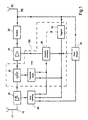
- Fig. 1 shows the basic circuit of an adaptive Repeaters, for example in a digital terrestrial broadcasting system for refreshing digital Signals can be used.
- the generally with 10 designated adaptive repeater comprises a signal input 15, to which a receiving antenna 17 is connected.
- the Receiving antenna 17 has a controllable amplifier 20 connected, which is known per se.
- the repeater 10 further contains a than Power amplifier built amplifier 40, a Bandpass filter 50, a signal output 60 and one thereon transmitting antenna 65 switched on.
- the repeater 10 includes an adaptive Amplifier stage 100.
- the adaptive amplifier stage 100 includes a step-by-step amplifier 30 which on the input side with the controllable amplifier 20 and is connected on the output side to the output stage 40.
- the adaptive amplifier stage 100 has one Clock 85 on the input side with the signal output 40 can be connected.
- a surveillance and Evaluation device 90 is, for example, with the output connected to the output stage 40 when the operating state is Vibration of the repeater 10 is monitored.
- the output is the monitoring and Evaluation device 90 with an input of a Touch pulse former 110 connected.
- the pulse pulse shaper 110 is on the output side again with the gradually adjustable Amplifier 30 and gain controller 80 connected.
- the monitoring and evaluation device 90 is further with an input of the gain control device 80 and optional with an entrance of the clock 85 connected.
- the clock 85 can both with an input of the pulse pulse shaper 110 as well an input of the gain controller 80 be connected.
- the output of the clock 85 can in turn with the input of the level indicator 70 and an input of the Monitoring and evaluation device 90 may be connected.
- the system sizes chosen in this way cause the adaptive repeater 10 starts to vibrate if its Gain is raised by about 9 dB or the Decoupling attenuation deteriorated by about 9 dB. It is further assumed that the surveillance and Evaluation device 90 in the present example as Vibration detector is formed, which detects when the adaptive repeater 10 changes into the vibration state.
- the clock generator 85 generates a clock pulse which activates the pulse pulse shaper 110 to generate a pulse with a duration of 40 ⁇ s. This pulse is fed to the step-by-step amplifier 30, which in response increases the gain of the repeater 10 by 9 dB.
- the total gain which is shown in FIG. 4 as curve 2, is therefore at time t 0 V 0 + 9 dB, which corresponds to the average decoupling loss.
- the average decoupling attenuation can be somewhat higher than the increased overall gain in order to prevent the repeater 10 from oscillating during an increase in the gain of the controllable amplifier 20 when the average gain is not reduced.
- the time course of the decoupling damping is shown in FIG. 4 as curve 1.
- the decoupling attenuation has dropped during the duration of the first pulse 3, for example due to a bird flying by, so that the overall gain of the adaptive repeater 10 is greater than the decoupling attenuation.
- the vibration detector 90 therefore detects that the repeater 10 is vibrating.
- the adaptive amplifier stage 100 recognizes that the repeater 10 has oscillated during the periodic increase in the gain V 0 of the repeater 10.
- the adaptive amplifier stage 100 is implemented in such a way that the gain of the step-by-step amplifier 30 is reduced to zero immediately after the oscillation of the repeater 10 has been determined, and at the same time the gain V 0 of the repeater 10 via the gain control device 80 by a predetermined small amount, for example is reduced by 0.5 dB, as shown in FIG. 4.
- the operational gain of the repeater 10 is now V 0 - 0.5 dB.
- the repeater 10 now works with a reduced gain, the preset safety distance, which ensures stable operation, is essentially retained.
- the decoupling attenuation rises again to a normal value after the brief drop, so that the vibration detector 90 initially no longer detects any use of vibration.
- the clock generator After 0.5 s has elapsed, the clock generator generates a further clock pulse, which is fed to the pulse pulse shaper 110 and the vibration detector 90 in order to signal that the periodic checking of the vibration behavior of the repeater 10 begins again.
- the pulse generator 110 generates a second pulse 4 with a duration of 40 ⁇ m, which in turn increases the gain of the step-by-step amplifier 30 and thus the overall gain of the repeater by 9 dB.
- the Vibration detector 90 detects the vibration state of the Repeaters 10 as well as the fact that no cyclical polling of the repeater 10 is present since it does not have a clock 85 Received clock pulse.
- the vibration detector 90 signals the use of vibrations of the repeater 10 to Clock 85, which then a clock pulse to Level indicator 70 and to the gain control device 80 transmits.
- the clock 85 activated level indicator 70 determines that the Signal level at signal output 60 is now below the optimized, preset signal level. to Initiation of cyclical monitoring of the The clock generator generates vibration behavior of the repeater 10 85 again a clock signal that both the vibration detector 90, the level indicator 70, the pulse generator 110 and the Gain control device 80 is supplied. at the example described here is the clock signal Control of periodic monitoring of the Vibration state of the repeater 10 regardless of that Power drop at signal output 60.
- the clock 85 depending on the signal level on Control output 60 of repeater 10.
- the clock 85 then generates a clock signal that is a premature cyclical Monitoring of the repeater 10 entails.
- the Tactile pulse shaper 110 subsequently generates a third Pulse 5, which causes the gain of the gradual controllable amplifier 30 is raised by 9 dB.
- the decoupling loss is higher than has assumed the average decoupling loss because z. B. the metallic aircraft flying past itself now far from repeater 10 occurs during cyclical monitoring does not show any vibration behavior.
- the Vibration detector 90 then causes the gain controller 80, the gain of the adjustable Amplifier 20 to raise a small amount of 0.5 dB.
- the level indicator 70 with the clock 85 be connected, which is then the period of the clock signal changed depending on the output power. For example, the period is shortened if the Level indicator 70 a predetermined performance drop on Signal output 60 detected. In this way, the Repeater 10 gain to the faster preset optimal gain value become. Thanks to the invention it is therefore possible to Repeater 10 with almost the entire operating time to let the maximum possible gain work, whereby the Maintain the predetermined safety distance becomes.
- the output signal Limiting the amplitude can limit the amplitude Means may be provided, which are not shown.
- Such limiter circuits are generally known.
- a person skilled in the art can also use diode limiters, for example bias voltage controlled by clock 85 or Limiter amplifier with the clock signal from the clock generator 85 switchable limiter threshold or arrangements Amplifier stages with a fixed threshold and subsequent switchable attenuators - in connection with an enlargement contrary to its weakening the gain increase in gradually adjustable Amplifier 30 - choose.
- Adaptive repeaters can at least partially or entirely as an inexpensive integrated circuit in one common function block can be summarized.
Landscapes
- Engineering & Computer Science (AREA)
- Computer Networks & Wireless Communication (AREA)
- Signal Processing (AREA)
- Radio Relay Systems (AREA)
- Amplifiers (AREA)
- Control Of Amplification And Gain Control (AREA)
Description
- Fig. 1
- ein Blockschaltbild eines adaptiven Repeaters mit einer Schwingeinsatz-Überwachung,
- Fig. 2
- ein Verstärkungs-Zeit-Diagramm der geregelten Verstärkung des regelbaren Verstärkers,
- Fig. 3
- Zeit-Diagramm einer beispielhaften Impulsfolge, die vom in Fig. 1 gezeigten Tastimpulsformer zur Steuerung des stufenweisen regelbaren Verstärkers erzeugt wird, und
- Fig. 4
- ein Verstärkungs-Zeit-Diagramm der Gesamtverstärkung des erfindungsgemäßen adaptiven Repeaters nach Fig. 1.
Claims (16)
- Vorrichtung zur geregelten Verstärkung von digitalen Signalen insbesondere für ein digitales Rundfunksystem umfassendgekennzeichnet durcheinen Signaleingang (15) undeinen Signalausgang (60),wobei die Vorrichtung (10) eine voreingestellte Verstärkung (Vo) liefert,
eine Einrichtung (100) zum impulsförmigen Erhöhen der voreingestellten Verstärkung um einen ersten vorbestimmten Betrag in vorbestimmten zeitlichen Abständen für jeweils eine vorbestimmte Zeitdauer und durch
eine Überwachungs- und Auswerteeinrichtung (90) zur Überwachung und Auswertung des Betriebszustandes der Vorrichtung (10) wenigstens in den vorbestimmten zeitlichen Abständen,
wobei in Abhängigkeit des Ausgangsignals der Überwachungs- und Auswerteeinrichtung (90) eine Vergrößerung oder eine Verkleinerung der voreingestellten Verstärkung um einen zweiten Betrag erfolgt. - Vorrichtung nach Anspruch 1,
gekennzeichnet durch
einen ersten regelbaren Verstärker (20) zur Lieferung der voreingestellten Verstärkung (Vo),
wobei die Einrichtung (100) zum zeitweisen Erhöhen der Verstärkung einen zweiten regelbaren Verstärker (30), einen Taktgeber (85) und einen mit dem zweiten regelbaren Verstärker (30) verbundenen Tastimpulsformer (110) aufweist. - Vorrichtung nach Anspruch 2,
gekennzeichnet durch
eine Einrichtung zur Verstärkungssteuerung (80), die eingangsseitig mit dem Taktgeber (85) und der Überwachungs- und Auswerteeinrichtung (90) sowie ausgangsseitig mit dem ersten Verstärker (20) verbunden ist, zur Verkleinerung oder Vergrößerung der voreingestellten Verstärkung um den zweiten vorbestimmten Betrag. - Vorrichtung nach Anspruch 2 oder 3,
dadurch gekennzeichnet, daß dem zweiten Verstärker (30) eine Endstufe (40) und ein Bandpaßfilter (50) nachgeschaltet sind. - Vorrichtung nach einem der Ansprüche 2 bis 4,
gekennzeichnet durch einen Pegelindikator (70), der eingangsseitig mit dem Signalausgang (60) und ausgangsseitig mit der Verstärkungs-Steuerungseinrichtung (80) verbunden ist, zur Erhöhung der voreingestellten Verstärkung um einen vorbestimmten Betrag. - Vorrichtung nach einem der Ansprüche 3 bis 5,
dadurch gekennzeichnet, daß die Verstärkungs-Steuerungseinrichtung (80) mit dem Taktimpulsformer (110) verbunden ist und unter Ansprechen auf diesen unterschiedliche Verstärkersteuerungssignale erzeugt. - Vorrichtung nach einem der Ansprüche 1 bis 6,
dadurch gekennzeichnet, daß die Überwachungs- und Auswerteeinrichtung (90) als Betriebszustand der Vorrichtung (10) deren Schwingungsverhalten überwacht und auswertet. - Vorrichtung nach einem der Ansprüche 4 bis 7,
dadurch gekennzeichnet, daß die Überwachungs- und Auswerteeinrichtung (90) als Betriebszustand der Vorrichtung (10) deren Änderung der Stromaufnahme überwacht und auswertet. - Vorrichtung nach einem der Ansprüche 4 bis 7,
dadurch gekennzeichnet, daß die Verstärkung der Vorrichtung (10) ampltitudenbegrenzt ist und die Überwachungs- und Auswerteeinrichtung (90) als Betriebszustand der Vorrichtung (10) die Oberwellen im Ausgangssignal der Endstufe (40) überwacht und auswertet. - Vorrichtung nach einem der Ansprüche 1 bis 7,
dadurch gekennzeichnet, daß die Überwachungs- und Auswerteeinrichtung (90) als Betriebszustand der Vorrichtung (10) die Bitfehlerrate des empfangenen digitalen Signal überwacht und mit einem vorbestimmten Wert vergleicht. - Vorrichtung nach einem der Ansprüche 4 bis 10, dadurch gekennzeichnet, daß die Überwachungs- und Auswerteeinrichtung (90) als Betriebszustand der Vorrichtung (10) die Welligkeit der Übertragungsfunktion im Frequenzbereich überwacht und auswertet.
- Vorrichtung nach nach einem der Ansprüche 4 bis 10,
dadurch gekennzeichnet, daß die Überwachungs- und Auswerteeinrichtung (90) als Betriebszustand der Vorrichtung (10) die Reduzierung oder das Verschwinden von modulationsbedingten Pegelschwankungen im verstärkten Signal im Frequenzbereich überwacht und auswertet. - Vorrichtung nach einem der Ansprüche 1 bis 12,
dadurch gekennzeichnet, daß am Signaleingang (15) eine Empfangsantenne (17) und am Signalausgang (60) eine Sendeantenne (65) angeschaltet ist. - Verfahren zum adaptiven Regeln des Verstärkungsfaktors einer Verstärkervorrichtung nach einem der Ansprüche 1 bis 13
mit folgenden Verfahrensschritten:a) Voreinstellen des Verstärkungsfaktors der Verstärkervorrichtung,b) periodisches impulsförmiges Anheben des Verstärkungsfaktors jeweils für eine einstellbare Zeitdauer um einen ersten einstellbaren Betrag,c) Überwachen und Auswerten des Betriebszustandes des Verstärkers wenigstens während des periodischen Anhebens des Verstärkungsfaktors nach Schritt c) undd) Verkleinern oder Vergrößern des voreingestellten Verstärkungsfaktors um einen zweiten einstellbaren Betrag in Abhängigkeit des ausgewerteten Betriebszustands. - Verfahren nach Anspruch 14,
dadurch gekennzeichnet, daß in Schritt c) als Betriebszustand der Schwingungszustand des Verstärkers überwacht und ausgewertet wird und daß der Verstärkungsfaktor um den zweiten einstellbaren Betrag vergößert wird, wenn in Schritt c) keine Schwingung des Verstärkers festgestellt wird, und daß der Verstärkungsfaktor um den zweiten einstellbaren Betrag verkleinert wird, wenn in Schritt c) eine Schwingung des Verstärkers festgestellt wird. - Verfahren nach Anspruch 14 oder 15,
dadurch gekennzeichnet, daß der Betriebszustand des Verstärkers auch außerhalb der Zeitabschnitte des periodischen Anhebens des Verstärkungsfaktors überwacht und ausgewertet wird und daß in Abhängigkeit des Betriebszustandes der voreingestellte Verstärkungsfaktor um einen dritten einstellbaren Betrag verkleinert oder vergrößert wird, wobei der dritte einstellbare Betrag größer ist als der zweite einstellbare Betrag.
Applications Claiming Priority (2)
| Application Number | Priority Date | Filing Date | Title |
|---|---|---|---|
| DE19752283A DE19752283C2 (de) | 1997-11-26 | 1997-11-26 | Schaltungsanordung und Verfahren zum adaptiven Regeln der Verstärkung eines rückgekoppelten Verstärkers für digitale Signale, insbesondere für ein digitales Rundfunksystem |
| DE19752283 | 1997-11-26 |
Publications (3)
| Publication Number | Publication Date |
|---|---|
| EP0920126A2 EP0920126A2 (de) | 1999-06-02 |
| EP0920126A3 EP0920126A3 (de) | 2001-01-17 |
| EP0920126B1 true EP0920126B1 (de) | 2004-02-11 |
Family
ID=7849812
Family Applications (1)
| Application Number | Title | Priority Date | Filing Date |
|---|---|---|---|
| EP98120169A Expired - Lifetime EP0920126B1 (de) | 1997-11-26 | 1998-10-28 | Verfahren und Vorrichtung zum adaptiven Regeln des Verstärkungsfaktors eines Verstärkers |
Country Status (3)
| Country | Link |
|---|---|
| EP (1) | EP0920126B1 (de) |
| AT (1) | ATE259555T1 (de) |
| DE (2) | DE19752283C2 (de) |
Cited By (1)
| Publication number | Priority date | Publication date | Assignee | Title |
|---|---|---|---|---|
| US9936396B2 (en) | 2013-04-29 | 2018-04-03 | Cellphone-Mate, Inc. | Apparatus and methods for radio frequency signal boosters |
Families Citing this family (5)
| Publication number | Priority date | Publication date | Assignee | Title |
|---|---|---|---|---|
| DE19923790A1 (de) * | 1997-11-26 | 2000-11-30 | Deutsche Telekom Ag | Schaltungsanordnung und Verfahren zum adaptiven Regeln der Verstärkung eines rückgekoppelten Verstärkers |
| DE50010141D1 (de) * | 1999-05-25 | 2005-06-02 | Deutsche Telekom Ag | Schaltungsanordnung und Verfahren zum adaptiven Regeln der Verstärkung eines rückgekoppelten Verstärkers |
| DE10155179B4 (de) * | 2001-11-12 | 2006-11-23 | Andrew Wireless Systems Gmbh | Digitaler Repeater mit Bandpassfilterung, adaptiver Vorentzerrung und Unterdrückung der Eigenschwingung |
| DE202005007183U1 (de) * | 2005-05-04 | 2006-05-18 | Kathrein-Werke Kg | DVB-T-Repeater, insbesondere zur portablen Indoor-Versorgung |
| GB0510385D0 (en) | 2005-05-20 | 2005-06-29 | British Broadcasting Corp | Improvements relating to on-channel repeaters |
Family Cites Families (3)
| Publication number | Priority date | Publication date | Assignee | Title |
|---|---|---|---|---|
| DE3401748A1 (de) * | 1984-01-19 | 1985-08-01 | Siemens AG, 1000 Berlin und 8000 München | Schaltungsanordnung fuer eine digitale pegelregelung |
| US4776032A (en) * | 1985-05-15 | 1988-10-04 | Nippon Telegraph And Telephone Corporation | Repeater for a same frequency with spillover measurement |
| GB9522198D0 (en) * | 1995-10-30 | 1996-01-03 | British Broadcasting Corp | Ofdm active deflectors |
-
1997
- 1997-11-26 DE DE19752283A patent/DE19752283C2/de not_active Expired - Fee Related
-
1998
- 1998-10-28 EP EP98120169A patent/EP0920126B1/de not_active Expired - Lifetime
- 1998-10-28 DE DE59810749T patent/DE59810749D1/de not_active Expired - Lifetime
- 1998-10-28 AT AT98120169T patent/ATE259555T1/de active
Cited By (3)
| Publication number | Priority date | Publication date | Assignee | Title |
|---|---|---|---|---|
| US9936396B2 (en) | 2013-04-29 | 2018-04-03 | Cellphone-Mate, Inc. | Apparatus and methods for radio frequency signal boosters |
| US10313893B2 (en) | 2013-04-29 | 2019-06-04 | Cellphone-Mate, Inc. | Apparatus and methods for radio frequency signal boosters |
| US11228921B2 (en) | 2013-04-29 | 2022-01-18 | Cellphone-Mate, Inc. | Apparatus and methods for radio frequency signal boosters |
Also Published As
| Publication number | Publication date |
|---|---|
| DE19752283A1 (de) | 1999-05-27 |
| EP0920126A2 (de) | 1999-06-02 |
| DE59810749D1 (de) | 2004-03-18 |
| EP0920126A3 (de) | 2001-01-17 |
| ATE259555T1 (de) | 2004-02-15 |
| DE19752283C2 (de) | 2000-08-10 |
Similar Documents
| Publication | Publication Date | Title |
|---|---|---|
| DE69023611T2 (de) | Digitales Funkverbindungssystem und Verfahren zur Einstellung der Sendeleistung in einem digitalen Funkverbidungssystem. | |
| DE69714975T2 (de) | Verfahren und gerät zur steuerung eines mobilen telefon-verstärkers | |
| DE2165019C3 (de) | Rundfunk-Fernmeldesystem | |
| DE69527549T2 (de) | Verfahren und vorrichtung für einen linearen sender | |
| DE3688047T2 (de) | Drahtloses synchronisationssystem fuer elektronisches artikel-ueberwachungssystem. | |
| DE19746084A1 (de) | Verfahren zum Betreiben eines Erfassungssystems für Eindringlinge | |
| EP0719027A2 (de) | Verfahren und Anordnung zur Echokompensation | |
| EP0920126B1 (de) | Verfahren und Vorrichtung zum adaptiven Regeln des Verstärkungsfaktors eines Verstärkers | |
| DE1158560B (de) | UEbertragungssystem fuer Signaluebertragung durch Impulskodemodulation und dabei anzuwendende Sender und Empfaenger | |
| DE1766745A1 (de) | Einrichtung zur selbsttaetigen Kanalauswahl fuer ein Nachrichtensystem mit mehreren UEbertragungskanaelen | |
| DE69227057T2 (de) | Signalstärkeanzeige eines Empfängers | |
| DE2118350C3 (de) | In einer Empfangskette für Nachrichtensignale angeordnete Rauschunterdrückungseinrichtung | |
| DE19642149A1 (de) | System zur Datenübertragung | |
| DE3700417C2 (de) | ||
| DE2728773C2 (de) | Funk-Fernsteuereinrichtung | |
| DE3048978A1 (de) | Optisches datenuebertragungssystem | |
| DE69804186T2 (de) | Vorrichtung und verfahren zur gleichzeitigen datenverbindung mit mehrzweckradarbetrieb | |
| DE69206918T2 (de) | Verfahren und einrichtung zur steuerung eines funksenders | |
| DE69731455T2 (de) | Interferenzdetektionsschaltung mit diskrimination durch amplitudenfrequenzdomänedefinition | |
| WO2003067784A1 (de) | Datenübertragungssystem mit einstellbarer sendeleistung | |
| EP1056198B1 (de) | Schaltungsanordnung und Verfahren zum adaptiven Regeln der Verstärkung eines rückgekoppelten Verstärkers | |
| EP1515447A1 (de) | Verfahren zur Unterdrückung von Störungen in einem Signalverarbeitungssystem und Signalverarbeitungssystem | |
| DE69304760T2 (de) | Verfahren zur Verstärkungsregelung in einem Empfänger für Datensignale | |
| DE2741952B2 (de) | Pegelregelung | |
| DE914946C (de) | Verfahren und Vorrichtung zur Empfindlichkeitsregelung von Signalempfangsanlagen |
Legal Events
| Date | Code | Title | Description |
|---|---|---|---|
| PUAI | Public reference made under article 153(3) epc to a published international application that has entered the european phase |
Free format text: ORIGINAL CODE: 0009012 |
|
| AK | Designated contracting states |
Kind code of ref document: A2 Designated state(s): AT BE CH CY DE DK ES FI FR GB GR IE IT LI LU MC NL PT SE |
|
| AX | Request for extension of the european patent |
Free format text: AL;LT;LV;MK;RO;SI |
|
| RIN1 | Information on inventor provided before grant (corrected) |
Inventor name: RAU, ARMIN, DR.-ING. Inventor name: FREIBURGER, GEORG, DR.-ING. Inventor name: DANNOWSKI, KLAUS, DR.-ING. Inventor name: LORENZ, RUDOLF WERNER, DR.-ING. |
|
| PUAL | Search report despatched |
Free format text: ORIGINAL CODE: 0009013 |
|
| AK | Designated contracting states |
Kind code of ref document: A3 Designated state(s): AT BE CH CY DE DK ES FI FR GB GR IE IT LI LU MC NL PT SE |
|
| AX | Request for extension of the european patent |
Free format text: AL;LT;LV;MK;RO;SI |
|
| RIC1 | Information provided on ipc code assigned before grant |
Free format text: 7H 03G 3/30 A, 7H 04B 7/26 B |
|
| 17P | Request for examination filed |
Effective date: 20010717 |
|
| AKX | Designation fees paid |
Free format text: AT BE CH CY DE DK ES FI FR GB GR IE IT LI LU MC NL PT SE |
|
| GRAP | Despatch of communication of intention to grant a patent |
Free format text: ORIGINAL CODE: EPIDOSNIGR1 |
|
| GRAS | Grant fee paid |
Free format text: ORIGINAL CODE: EPIDOSNIGR3 |
|
| GRAA | (expected) grant |
Free format text: ORIGINAL CODE: 0009210 |
|
| AK | Designated contracting states |
Kind code of ref document: B1 Designated state(s): AT BE CH CY DE DK ES FI FR GB GR IE IT LI LU MC NL PT SE |
|
| PG25 | Lapsed in a contracting state [announced via postgrant information from national office to epo] |
Ref country code: IT Free format text: LAPSE BECAUSE OF FAILURE TO SUBMIT A TRANSLATION OF THE DESCRIPTION OR TO PAY THE FEE WITHIN THE PRESCRIBED TIME-LIMIT;WARNING: LAPSES OF ITALIAN PATENTS WITH EFFECTIVE DATE BEFORE 2007 MAY HAVE OCCURRED AT ANY TIME BEFORE 2007. THE CORRECT EFFECTIVE DATE MAY BE DIFFERENT FROM THE ONE RECORDED. Effective date: 20040211 Ref country code: IE Free format text: LAPSE BECAUSE OF FAILURE TO SUBMIT A TRANSLATION OF THE DESCRIPTION OR TO PAY THE FEE WITHIN THE PRESCRIBED TIME-LIMIT Effective date: 20040211 Ref country code: FI Free format text: LAPSE BECAUSE OF FAILURE TO SUBMIT A TRANSLATION OF THE DESCRIPTION OR TO PAY THE FEE WITHIN THE PRESCRIBED TIME-LIMIT Effective date: 20040211 Ref country code: CY Free format text: LAPSE BECAUSE OF FAILURE TO SUBMIT A TRANSLATION OF THE DESCRIPTION OR TO PAY THE FEE WITHIN THE PRESCRIBED TIME-LIMIT Effective date: 20040211 |
|
| REG | Reference to a national code |
Ref country code: GB Ref legal event code: FG4D Free format text: NOT ENGLISH |
|
| REG | Reference to a national code |
Ref country code: CH Ref legal event code: EP |
|
| REG | Reference to a national code |
Ref country code: CH Ref legal event code: NV Representative=s name: ISLER & PEDRAZZINI AG |
|
| REG | Reference to a national code |
Ref country code: IE Ref legal event code: FG4D Free format text: GERMAN |
|
| REF | Corresponds to: |
Ref document number: 59810749 Country of ref document: DE Date of ref document: 20040318 Kind code of ref document: P |
|
| PG25 | Lapsed in a contracting state [announced via postgrant information from national office to epo] |
Ref country code: SE Free format text: LAPSE BECAUSE OF FAILURE TO SUBMIT A TRANSLATION OF THE DESCRIPTION OR TO PAY THE FEE WITHIN THE PRESCRIBED TIME-LIMIT Effective date: 20040511 Ref country code: GR Free format text: LAPSE BECAUSE OF FAILURE TO SUBMIT A TRANSLATION OF THE DESCRIPTION OR TO PAY THE FEE WITHIN THE PRESCRIBED TIME-LIMIT Effective date: 20040511 Ref country code: DK Free format text: LAPSE BECAUSE OF FAILURE TO SUBMIT A TRANSLATION OF THE DESCRIPTION OR TO PAY THE FEE WITHIN THE PRESCRIBED TIME-LIMIT Effective date: 20040511 |
|
| PG25 | Lapsed in a contracting state [announced via postgrant information from national office to epo] |
Ref country code: ES Free format text: LAPSE BECAUSE OF FAILURE TO SUBMIT A TRANSLATION OF THE DESCRIPTION OR TO PAY THE FEE WITHIN THE PRESCRIBED TIME-LIMIT Effective date: 20040522 |
|
| GBT | Gb: translation of ep patent filed (gb section 77(6)(a)/1977) |
Effective date: 20040602 |
|
| REG | Reference to a national code |
Ref country code: IE Ref legal event code: FD4D |
|
| PG25 | Lapsed in a contracting state [announced via postgrant information from national office to epo] |
Ref country code: LU Free format text: LAPSE BECAUSE OF NON-PAYMENT OF DUE FEES Effective date: 20041028 |
|
| PG25 | Lapsed in a contracting state [announced via postgrant information from national office to epo] |
Ref country code: MC Free format text: LAPSE BECAUSE OF NON-PAYMENT OF DUE FEES Effective date: 20041031 |
|
| ET | Fr: translation filed | ||
| PLBE | No opposition filed within time limit |
Free format text: ORIGINAL CODE: 0009261 |
|
| STAA | Information on the status of an ep patent application or granted ep patent |
Free format text: STATUS: NO OPPOSITION FILED WITHIN TIME LIMIT |
|
| 26N | No opposition filed |
Effective date: 20041112 |
|
| REG | Reference to a national code |
Ref country code: CH Ref legal event code: PCAR Free format text: ISLER & PEDRAZZINI AG;POSTFACH 1772;8027 ZUERICH (CH) |
|
| PG25 | Lapsed in a contracting state [announced via postgrant information from national office to epo] |
Ref country code: PT Free format text: LAPSE BECAUSE OF NON-PAYMENT OF DUE FEES Effective date: 20040711 |
|
| PGFP | Annual fee paid to national office [announced via postgrant information from national office to epo] |
Ref country code: AT Payment date: 20101020 Year of fee payment: 13 |
|
| PGFP | Annual fee paid to national office [announced via postgrant information from national office to epo] |
Ref country code: GB Payment date: 20101021 Year of fee payment: 13 |
|
| PGFP | Annual fee paid to national office [announced via postgrant information from national office to epo] |
Ref country code: BE Payment date: 20111024 Year of fee payment: 14 Ref country code: CH Payment date: 20111025 Year of fee payment: 14 Ref country code: NL Payment date: 20111025 Year of fee payment: 14 Ref country code: FR Payment date: 20111103 Year of fee payment: 14 |
|
| REG | Reference to a national code |
Ref country code: DE Ref legal event code: R081 Ref document number: 59810749 Country of ref document: DE Owner name: MEDIA BROADCAST GMBH, DE Free format text: FORMER OWNER: DEUTSCHE TELEKOM AG, 53113 BONN, DE Effective date: 20130304 |
|
| BERE | Be: lapsed |
Owner name: DEUTSCHE *TELEKOM A.G. Effective date: 20121031 |
|
| REG | Reference to a national code |
Ref country code: NL Ref legal event code: V1 Effective date: 20130501 |
|
| REG | Reference to a national code |
Ref country code: CH Ref legal event code: PL |
|
| REG | Reference to a national code |
Ref country code: AT Ref legal event code: MM01 Ref document number: 259555 Country of ref document: AT Kind code of ref document: T Effective date: 20121028 |
|
| GBPC | Gb: european patent ceased through non-payment of renewal fee |
Effective date: 20121028 |
|
| REG | Reference to a national code |
Ref country code: FR Ref legal event code: ST Effective date: 20130628 |
|
| PG25 | Lapsed in a contracting state [announced via postgrant information from national office to epo] |
Ref country code: BE Free format text: LAPSE BECAUSE OF NON-PAYMENT OF DUE FEES Effective date: 20121031 Ref country code: CH Free format text: LAPSE BECAUSE OF NON-PAYMENT OF DUE FEES Effective date: 20121031 Ref country code: LI Free format text: LAPSE BECAUSE OF NON-PAYMENT OF DUE FEES Effective date: 20121031 Ref country code: GB Free format text: LAPSE BECAUSE OF NON-PAYMENT OF DUE FEES Effective date: 20121028 Ref country code: AT Free format text: LAPSE BECAUSE OF NON-PAYMENT OF DUE FEES Effective date: 20121028 |
|
| PG25 | Lapsed in a contracting state [announced via postgrant information from national office to epo] |
Ref country code: NL Free format text: LAPSE BECAUSE OF NON-PAYMENT OF DUE FEES Effective date: 20130501 Ref country code: FR Free format text: LAPSE BECAUSE OF NON-PAYMENT OF DUE FEES Effective date: 20121031 |
|
| PGFP | Annual fee paid to national office [announced via postgrant information from national office to epo] |
Ref country code: DE Payment date: 20141031 Year of fee payment: 17 |
|
| REG | Reference to a national code |
Ref country code: DE Ref legal event code: R119 Ref document number: 59810749 Country of ref document: DE |
|
| PG25 | Lapsed in a contracting state [announced via postgrant information from national office to epo] |
Ref country code: DE Free format text: LAPSE BECAUSE OF NON-PAYMENT OF DUE FEES Effective date: 20160503 |