EP0920144A2 - Übertragungssystem zur Übertragung von Digitalsignalen in einem Funk-Teilnehmeranschlussnetz - Google Patents
Übertragungssystem zur Übertragung von Digitalsignalen in einem Funk-Teilnehmeranschlussnetz Download PDFInfo
- Publication number
- EP0920144A2 EP0920144A2 EP98121401A EP98121401A EP0920144A2 EP 0920144 A2 EP0920144 A2 EP 0920144A2 EP 98121401 A EP98121401 A EP 98121401A EP 98121401 A EP98121401 A EP 98121401A EP 0920144 A2 EP0920144 A2 EP 0920144A2
- Authority
- EP
- European Patent Office
- Prior art keywords
- radio
- base station
- digital signals
- bits per
- signal element
- Prior art date
- Legal status (The legal status is an assumption and is not a legal conclusion. Google has not performed a legal analysis and makes no representation as to the accuracy of the status listed.)
- Withdrawn
Links
Images

Classifications
-
- H—ELECTRICITY
- H04—ELECTRIC COMMUNICATION TECHNIQUE
- H04W—WIRELESS COMMUNICATION NETWORKS
- H04W16/00—Network planning, e.g. coverage or traffic planning tools; Network deployment, e.g. resource partitioning or cells structures
-
- H—ELECTRICITY
- H04—ELECTRIC COMMUNICATION TECHNIQUE
- H04J—MULTIPLEX COMMUNICATION
- H04J4/00—Combined time-division and frequency-division multiplex systems
-
- H—ELECTRICITY
- H04—ELECTRIC COMMUNICATION TECHNIQUE
- H04L—TRANSMISSION OF DIGITAL INFORMATION, e.g. TELEGRAPHIC COMMUNICATION
- H04L1/00—Arrangements for detecting or preventing errors in the information received
- H04L1/0001—Systems modifying transmission characteristics according to link quality, e.g. power backoff
- H04L1/0002—Systems modifying transmission characteristics according to link quality, e.g. power backoff by adapting the transmission rate
-
- H—ELECTRICITY
- H04—ELECTRIC COMMUNICATION TECHNIQUE
- H04B—TRANSMISSION
- H04B7/00—Radio transmission systems, i.e. using radiation field
- H04B7/24—Radio transmission systems, i.e. using radiation field for communication between two or more posts
- H04B7/26—Radio transmission systems, i.e. using radiation field for communication between two or more posts at least one of which is mobile
- H04B7/2643—Radio transmission systems, i.e. using radiation field for communication between two or more posts at least one of which is mobile using time-division multiple access [TDMA]
- H04B7/2659—Radio transmission systems, i.e. using radiation field for communication between two or more posts at least one of which is mobile using time-division multiple access [TDMA] for data rate control
-
- H—ELECTRICITY
- H04—ELECTRIC COMMUNICATION TECHNIQUE
- H04W—WIRELESS COMMUNICATION NETWORKS
- H04W84/00—Network topologies
- H04W84/02—Hierarchically pre-organised networks, e.g. paging networks, cellular networks, WLAN [Wireless Local Area Network] or WLL [Wireless Local Loop]
- H04W84/10—Small scale networks; Flat hierarchical networks
- H04W84/14—WLL [Wireless Local Loop]; RLL [Radio Local Loop]
Definitions
- a radio subscriber access network is a - typically area-wide - system of radio cells, each of which contains a - usually centrally located - stationary base station, around which the network terminations are more or less homogeneously distributed within a radius of 1 km, for example (NTs) of the radio subscribers.
- NTs for example
- Such a radio cell is outlined in the drawing in FIG. 1, in which the base station is designated by BS and the radio subscribers (or their network terminations) by NT. Since in a radio system the radio field attenuation increases quadratically with the distance, the radio field strength at the cell edge is considerably smaller than in the cell interior; this attenuation is illustrated in FIG. 1 with concentric circles around the base station. For example, additional damping caused by rain and also distance-dependent can greatly reduce the reception power available at the network terminations at the cell edge.
- such a radio system which is basically a point-to-multipoint system represents (the transmitter of the base station can reach the receiver of many participants), the signal transmission from the base station down to the radio subscribers towards time division multiplex (TDM) a 155 Mbit / s bit stream going on and signal transmission from the radio subscribers up to the base station in a TDMA (Time Division Multiple Access) access procedure.
- TDM time division multiplex
- Such a uniform power distribution as expressed in the flat surface of the diagram hatched in FIG. 2, is ideal in a radio system in which all network terminations are at the same constant distance from the base station. If the time period T is assumed to be constant, so that it does not have to be shown in the diagram, and if the distance r from the base station is introduced as a third variable, the transmission power P required for a constant bit error rate is obtained, which is shaded in FIG.
- the reception power at the individual network terminations NT can be measured within a radio cell and used as a measure for the respective radio field attenuation, in accordance with which the transmission power of the relevant one Network termination is adjusted accordingly.
- the individual network terminations NT of a radio cell can be controlled one after the other with adaptive antennas, the higher gain of such antennas compared to omnidirectional antennas with the same transmission power correspondingly increasing the bridging Distances allowed.
- adaptive antennas are only at the beginning of development.
- Different modulation methods can also be used for more distant network terminations on the one hand and network terminations in the vicinity of the base station on the other hand, for example 16QAM for the inner area and QPSK for the outer area of the radio cell.
- the required signal / interference ratio (S / N) is 7 dB lower with QPSK than with 16QAM.
- S / N The required signal / interference ratio
- With 16QAM however, the requirements for linearity increase, especially for the amplifiers.
- Such a method is particularly suitable for OFDM.
- the invention now shows another way of optimization the power distribution within a radio cell.
- the invention relates to a system for the transmission of digital signals in a radio subscriber access network, in particular in a broadband RLL (Radio in the Local Loop) subscriber access network;
- this transmission system is according to the invention characterized in that the digital signal transmission from the base station of a radio cell to those in the radio cell radio stations located in the total bit clock of the system in time-division multiplex radio channels of different bit numbers each Useful signal element (symbol) in such a way that every connection from the base station to a radio subscriber towards its distance from the base station one radio channel of the required number of bits per useful signal element is assigned so that for larger or smaller Radio users located at a distance from the base station certain digital signals in radio channels with accordingly transmit higher or lower number of bits per useful signal element the multiple transmitted bits on the receiving end again combined into a single bit become.
- RLL Radio in the Local Loop
- the number of bits per useful signal element i.e. the repetition factor, with the one bit in immediate succession is transmitted several times, any integer n be, so that a correspondingly fine, possibly also adaptive Adaptation to the respective radio channel attenuation is possible.
- the Increase in the number of bits per useful signal element or, otherwise said, the multiple, immediately successive transmission of a bit within the total bit rate of the system summarizing into a correspondingly "long" bit (or a single symbol) has the following effect:
- any such doubling of the number of bits per symbol halves the bandwidth of the signal; the transmission of the total transmission power P s within half the bandwidth increases the power / Hz by 3 dB each.
- FIG 1, FIG 2 and FIG 3 have already been above explained, so that further explanations on this Place unnecessary.
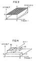
- FIG. 4 illustrates the division in one exemplary embodiment the total transmission power of the base station (BS in FIG 1) a radio cell (FIG 1) on the frequency bands of time-division multiplex radio channels different number of bits per useful signal element (Symbol), the representation in FIG. 4 being only three such time-division multiplex radio channels K1, K2, K3 extends.
- Connections to further away from the base station located radio subscribers are correspondingly narrowband Radio channels assigned a larger number of bits per symbol, in which the digital signals transmit at higher power / Hz and connections to a smaller distance from the Base stations located radio subscribers will be accordingly broadband radio channels assigned to a smaller number of bits per symbol, in which the digital signals with lower power / Hz
- channel K1 may be one Connection with good transfer ratios to one is not Assigned radio subscribers far from the base station be towards which the digital signals with a relative small number of bits per symbol can be transmitted; of the Radio channel K1 is therefore comparatively broadband, and the digital signals are with relatively low power / Hz transfer.
- channel K3 likes a connection with good ones Transfer ratios to a noticeably further from the Base station be assigned to remote radio subscribers the digital signals with a larger one (in the example twice) the number of bits per symbol must be transferred; of the Radio channel K3 is therefore less broadband, and Digital signals are with correspondingly higher power / Hz transfer.
- the channel K2 a connection with bad transference to a more or less Assigned radio subscribers far from the base station to which the digital signals go because of these bad transmission ratios with an even bigger one (in the example three times) the number of bits per symbol Need to become; the radio channel K2 is therefore even narrower, and the digital signals are with even higher power / Hz transfer.
- the transmission side e.g. by appropriate multiple scanning of a useful signal element (symbol) obtained in the sum bit clock of the system's multiple transmitted bits are received again combined into a correspondingly long bit, then the underlying useful signal element (symbol) represents.
- a signal sampling circuit can be provided in which the optimal To determine adaptively the sampling time for the sampling is.
- an integrator with a variable Length can be provided in which the signal energy of the total (multiplied) bit duration accumulated and simultaneously the noise power is optimally suppressed.
Landscapes
- Engineering & Computer Science (AREA)
- Computer Networks & Wireless Communication (AREA)
- Signal Processing (AREA)
- Quality & Reliability (AREA)
- Mobile Radio Communication Systems (AREA)
Abstract
Description
Beispielsweise durch Regen bedingte, ebenfalls entfernungsabhängige Zusatzdämpfungen können die bei den Network Terminations am Zellenrand zur Verfügung stehende Empfangsleistung zusätzlich sehr stark verringern.
Alle Network Terminations (NT in FIG 1) verarbeiten die volle Summenbitrate von 155 Mbit/s des Abwärts-Zeitmultiplexsignals, obwohl in der Regel nur ein kleiner Teil dieser Bitrate für die jeweilige Network Termination bestimmt ist. Die hohe Bandbreite des Zeitmultiplexsignals führt dabei zu einem entsprechend schlechten Signal/Stör-Leistungsverhältnis am teilnehmerindividuellen Empfänger.
Die Sendeleistung insbesondere der Basisstation (BS in FIG 1) ist aus telekommunikationsrechtlichen und/oder technischen Gründen begrenzt, woraus sich bei gegebenen Parametern wie RF-Sendefrequenz, Summenbitrate, Antennengewinn, Signal/Stör-Verhältnis der grösstmögliche Zellenradius ergibt; bei denjenigen Network Terminations (NT in FIG 1), die näher an der Basisstation liegen, ist die Empfangsleistung - und damit auch das Signal/Stör-Leistungsverhältnis - dabei grösser, als dies für eine vorgegebene Bitfehlerrate nötig ist, so dass insoweit Sendeleistung 'verschenkt' wird.
Nimmt man die Zeitdauer T als konstant an, so dass sie im Diagramm nicht dargestellt werden muss, und führt man den Abstand r von der Basisstation als dritte Variable ein, so erhält man für die für eine konstante Bitfehlerrate benötigte Sendeleistung P die in FIG 3 schattiert angelegte gekrümmte Oberfläche, die sich ergibt, indem man für jeden Punkt der Ebene die benötigte Leistung P für eine vorgegebene Bitfehlerrate (z.B. 10-9) aufträgt. Bei vernachlässigbaren Multipatheffekten ist P von der Frequenz kaum abhängig. Die in FIG 2 dargestellte Leistungsverteilung nach dem 'water-filling'-Algorithmus, d.h. bei vom Abstand r unabhängiger Leistung Ps, ist in FIG 3 wiederum schraffiert eingezeichnet. Der Abstand zwischen der gekrümmten und der geraden Oberfläche ist dann ein Maß für die oben so apostrophierte, bei einem gegebenen Abstand r 'verschenkte' Leistung.
Zur Optimierung der Leistungsverteilung in Abwärtsrichtung (von der Basistation BS zu den Funkteilnehmern (NT) hin) können mit adaptiven Antennen die einzelnen Network Terminations NT einer Funkzelle nacheinander angesteuert werden, wobei der höhere Gewinn solcher Antennen gegenüber omnidirektionalen Antennen bei gleicher Sendeleistung die Überbrückung entsprechend größerer Entfernungen erlaubt. Adaptive Antennen stehen allerdings erst am Anfang der Entwicklung.
Man kann auch für weiter entfernte Network Terminations einerseits und Network Terminations im Nahbereich der Basisstation andererseits unterschiedliche Modulationsverfahren verwenden, beispielsweise 16QAM für den inneren und QPSK für den äusseren Bereich der Funkzelle. Das erforderliche Signal/Stör-Verhältnis (S/N) ist bei QPSK um 7 dB kleiner als bei 16QAM. Bei 16QAM erhöhen sich allerdings, speziell bei den Verstärkern, die Anforderungen an die Linearität. Ein solches Verfahren ist vor allem für OFDM geeignet.
- FIG 1
- das typische Bild einer Funkzelle mit darin auftretenden Dämpfungen und
- FIG 2
- die gleichmäßige Verteilung der zur Verfügung stehenden Gesamt-Sendeleistung über der Zeit und der Frequenz;
- FIG 3
- verdeutlicht den Verlauf der für eine konstante Bitfehlerrate benötigten Sendeleistung in Abhängigkeit vom Abstand des Funkteilnehmers von der sendenden Basisstation, und
- FIG 4
- zeigt eine Aufteilung der Gesamt-Sendeleistung über der Frequenz-/Zeit-Ebene auf Funkkanäle unterschiedlicher Bitanzahl je Symbol.
Claims (2)
- System zur Übertragung von Digitalsignalen in einem Funk-Teilnehmeranschlussnetz, insbesondere in einem breitbandigen RLL(Radio in the Local Loop)-Teilnehmeranschlussnetz,
dadurch gekennzeichnet,
dass die Digitalsignalübertragung von der Basisstation einer Funkzelle zu den in der Funkzelle befindlichen Funkteilnehmern hin im Summenbittakt des Systems in Zeitmultiplex-Funkkanälen unterschiedlicher Bitanzahl je Nutzsignalelement in der Weise vor sich geht, dass jeder Verbindung von der Basisstation zu einem Funkteilnehmer hin nach Maßgabe von dessen Entfernung von der Basisstation ein Funkkanal der benötigten Bitanzahl je Nutzsignalelement zugeordnet wird, so dass die für in grösserer oder kleinerer Entfernung von der Basisstation befindliche Funkteilnehmer bestimmten Digitalsignale in Funkkanälen mit entsprechend höherer oder niedrigerer Bitanzahl je Nutzsignalelement übertragen werden, wobei die mehrfach übertragenen Bits empfangsseitig jeweils wieder zu einem einzigen Bit zusammengefasst werden. - Übertragungssystem nach Anspruch 1,
dadurch gekennzeichnet,
auf Funkstrecken mit unzureichendem Signal/Stör-Verhältnis die Digitalsignale auch zu näher zur Basisstation liegenden Funkteilnehmern mit entsprechend höherer Bitanzahl je Nutzsignalelement übertragen werden.
Applications Claiming Priority (2)
| Application Number | Priority Date | Filing Date | Title |
|---|---|---|---|
| DE19752197 | 1997-11-25 | ||
| DE19752197A DE19752197A1 (de) | 1997-11-25 | 1997-11-25 | Übertragungssystem zur Übertragung von Digitalsignalen in einem Funk-Teilnehmeranschlußnetz |
Publications (2)
| Publication Number | Publication Date |
|---|---|
| EP0920144A2 true EP0920144A2 (de) | 1999-06-02 |
| EP0920144A3 EP0920144A3 (de) | 2000-11-08 |
Family
ID=7849765
Family Applications (1)
| Application Number | Title | Priority Date | Filing Date |
|---|---|---|---|
| EP98121401A Withdrawn EP0920144A3 (de) | 1997-11-25 | 1998-11-11 | Übertragungssystem zur Übertragung von Digitalsignalen in einem Funk-Teilnehmeranschlussnetz |
Country Status (3)
| Country | Link |
|---|---|
| US (1) | US6577612B1 (de) |
| EP (1) | EP0920144A3 (de) |
| DE (1) | DE19752197A1 (de) |
Cited By (1)
| Publication number | Priority date | Publication date | Assignee | Title |
|---|---|---|---|---|
| EP1067728A3 (de) * | 1999-07-07 | 2003-07-09 | Siemens Aktiengesellschaft | Verfahren zur Zuweisung von Übertragungskapazität zu Verbindungen in einem Funk-Kommunikationssystem |
Families Citing this family (2)
| Publication number | Priority date | Publication date | Assignee | Title |
|---|---|---|---|---|
| US6950444B1 (en) * | 1999-08-24 | 2005-09-27 | Paradyne Corporation | System and method for a robust preamble and transmission delimiting in a switched-carrier transceiver |
| US20020167949A1 (en) * | 1998-02-26 | 2002-11-14 | Gordon Bremer | Apparatus and method for asynchronous transfer mode (ATM) adaptive time domain duplex (ATDD) communication |
Family Cites Families (8)
| Publication number | Priority date | Publication date | Assignee | Title |
|---|---|---|---|---|
| SE460749B (sv) | 1988-03-15 | 1989-11-13 | Ericsson Telefon Ab L M | Foerfarande att oeverfoera datainformation i ett cellindelat mobilradiokommunikationssystem |
| US5210771A (en) * | 1991-08-01 | 1993-05-11 | Motorola, Inc. | Multiple user spread-spectrum communication system |
| SE516173C2 (sv) * | 1993-02-16 | 2001-11-26 | Ericsson Telefon Ab L M | Anordning för telekommunikation |
| US5579306A (en) * | 1994-09-01 | 1996-11-26 | Ericsson Inc. | Time and frequency slot allocation system and method |
| US5822310A (en) * | 1995-12-27 | 1998-10-13 | Ericsson Inc. | High power short message service using broadcast control channel |
| EP0845916B1 (de) * | 1996-12-02 | 2005-03-02 | Telefonaktiebolaget LM Ericsson (publ) | Punkt zu multipunkt Funksystem |
| CA2246385A1 (en) | 1996-12-16 | 1998-06-25 | Gilles Colmant | Installation for exchanging articles, in particular gas cylinders |
| US6044486A (en) * | 1997-09-11 | 2000-03-28 | Uniden America Corporation | Method and device for majority vote optimization over wireless communication channels |
-
1997
- 1997-11-25 DE DE19752197A patent/DE19752197A1/de not_active Ceased
-
1998
- 1998-11-11 EP EP98121401A patent/EP0920144A3/de not_active Withdrawn
- 1998-11-25 US US09/200,112 patent/US6577612B1/en not_active Expired - Fee Related
Cited By (2)
| Publication number | Priority date | Publication date | Assignee | Title |
|---|---|---|---|---|
| EP1067728A3 (de) * | 1999-07-07 | 2003-07-09 | Siemens Aktiengesellschaft | Verfahren zur Zuweisung von Übertragungskapazität zu Verbindungen in einem Funk-Kommunikationssystem |
| US6928268B1 (en) | 1999-07-07 | 2005-08-09 | Siemens Aktiengesellschaft | Method for allocating a transmission capacity to connections in a radio communication system |
Also Published As
| Publication number | Publication date |
|---|---|
| EP0920144A3 (de) | 2000-11-08 |
| US6577612B1 (en) | 2003-06-10 |
| DE19752197A1 (de) | 1999-05-27 |
Similar Documents
| Publication | Publication Date | Title |
|---|---|---|
| DE19752200C1 (de) | Übertragungssystem zum Steuern der Sendeleistung in Funkzellen eines Funk-Teilnehmeranschlußnetzes | |
| DE69131719T2 (de) | Verfahren und einrichtung zur dynamischen verteilung der last eines kommunikationskanals in einem zellularen kommunikationssystem | |
| DE60036837T2 (de) | Mediumzuteilungsverfahren | |
| DE60113775T2 (de) | Verfahren und Anordnung zur Steuerung der Stärke der Aufwärtssignalen in einem Satelliten Übertragungssystem mit Fehlergleichung | |
| DE69330964T2 (de) | Verfahren und anordnung zur dynamischen zuteilung mehrerer trägerwellenkanäle für mehrfachzugriff durch frequenzmultiplex | |
| DE60027449T2 (de) | Adaptives modulationssystem und -verfahren für tdma-systeme | |
| EP0210698A2 (de) | Digitales Funkübertragungssystem mit variabler Zeitschlitzdauer der Zeitschlitze im Zeitmultiplexrahmen | |
| DE3642213C2 (de) | Satelliten-Nachrichtenübertragungssystem | |
| DE3447107A1 (de) | Verfahren zur nachrichtenuebertragung in einem digitalen funkuebertragungssystem | |
| EP0890227B1 (de) | Punkt-zu-mehrpunkt funkübertragungssystem | |
| DE10000292B4 (de) | Automatische Verstärkungssteuerung für einen Empfänger und Verfahren zur automatischen Verstärkungssteuerung | |
| DE69533687T2 (de) | Verfahren und Vorrichtung zur Messung der Impulsantwort eines Funkkanals | |
| WO1995017798A2 (de) | Steuerungseinrichtung für die funkversorgung in einem zellularen, digitalen mobilkommunikationssystem | |
| EP0772923B1 (de) | Richtfunksystem für punkt-zu-mehrpunkt verbindungen | |
| EP1623547B1 (de) | Verfahren und Einrichtung für die drahtlose Mehrträgerkommunikation mit dynamischer Aufteilung der Frequenzbreite und Anzahl der Subbänder | |
| DE4132200A1 (de) | Zeitmultiplex-verfahren zur bestimmung der mittleren phasenaenderung eines empfangssignals | |
| EP0920144A2 (de) | Übertragungssystem zur Übertragung von Digitalsignalen in einem Funk-Teilnehmeranschlussnetz | |
| EP0612460B1 (de) | Funkübertragungsverfahren mittels einer ortsfesten basisstation und einer vielzahl voneinander unabhängiger ortsfester teilnehmerstationen | |
| DE60314933T2 (de) | Breitbandübertragung mit Frequenzanpassung abhängig von der Kanalschätzung | |
| DE19726120A1 (de) | Verfahren zur Datenübertragung auf einem gemeinsamen Medium | |
| EP1090520B1 (de) | Verfahren und basisstation zur übertragung von organisationsinformationen in einem funk-kommunikationssystem | |
| DE69937550T2 (de) | Verfahren und vorrichtung für drahtlose nachrichtenübertragung | |
| DE19649853C2 (de) | Repeater für Funksignale | |
| DE4337244A1 (de) | Mobilfunksystem mit einem Zwischenverstärker | |
| EP0151281B1 (de) | Digitales Zellenfunksystem mit Zeitmultiplex |
Legal Events
| Date | Code | Title | Description |
|---|---|---|---|
| PUAI | Public reference made under article 153(3) epc to a published international application that has entered the european phase |
Free format text: ORIGINAL CODE: 0009012 |
|
| AK | Designated contracting states |
Kind code of ref document: A2 Designated state(s): DE FR GB IT |
|
| AX | Request for extension of the european patent |
Free format text: AL;LT;LV;MK;RO;SI |
|
| PUAL | Search report despatched |
Free format text: ORIGINAL CODE: 0009013 |
|
| AK | Designated contracting states |
Kind code of ref document: A3 Designated state(s): AT BE CH CY DE DK ES FI FR GB GR IE IT LI LU MC NL PT SE |
|
| AX | Request for extension of the european patent |
Free format text: AL;LT;LV;MK;RO;SI |
|
| RIC1 | Information provided on ipc code assigned before grant |
Free format text: 7H 04Q 7/36 A, 7H 04L 1/00 B, 7H 04J 4/00 B |
|
| 17P | Request for examination filed |
Effective date: 20001204 |
|
| AKX | Designation fees paid |
Free format text: DE FR GB IT |
|
| 17Q | First examination report despatched |
Effective date: 20030602 |
|
| STAA | Information on the status of an ep patent application or granted ep patent |
Free format text: STATUS: THE APPLICATION IS DEEMED TO BE WITHDRAWN |
|
| 18D | Application deemed to be withdrawn |
Effective date: 20031013 |