EP0920167B1 - Appareil muni d'une prise pour casque d'écoute - Google Patents
Appareil muni d'une prise pour casque d'écoute Download PDFInfo
- Publication number
- EP0920167B1 EP0920167B1 EP98309318A EP98309318A EP0920167B1 EP 0920167 B1 EP0920167 B1 EP 0920167B1 EP 98309318 A EP98309318 A EP 98309318A EP 98309318 A EP98309318 A EP 98309318A EP 0920167 B1 EP0920167 B1 EP 0920167B1
- Authority
- EP
- European Patent Office
- Prior art keywords
- socket
- retaining means
- headset
- circuit board
- telephone
- Prior art date
- Legal status (The legal status is an assumption and is not a legal conclusion. Google has not performed a legal analysis and makes no representation as to the accuracy of the status listed.)
- Expired - Lifetime
Links
- 230000000295 complement effect Effects 0.000 claims 1
- 230000001413 cellular effect Effects 0.000 description 6
- 230000008878 coupling Effects 0.000 description 2
- 238000010168 coupling process Methods 0.000 description 2
- 238000005859 coupling reaction Methods 0.000 description 2
- 238000003780 insertion Methods 0.000 description 2
- 230000037431 insertion Effects 0.000 description 2
- 230000001154 acute effect Effects 0.000 description 1
- 230000000994 depressogenic effect Effects 0.000 description 1
- 238000011038 discontinuous diafiltration by volume reduction Methods 0.000 description 1
- 230000001771 impaired effect Effects 0.000 description 1
- 238000000034 method Methods 0.000 description 1
- 229910000679 solder Inorganic materials 0.000 description 1
Images


Classifications
-
- H—ELECTRICITY
- H04—ELECTRIC COMMUNICATION TECHNIQUE
- H04M—TELEPHONIC COMMUNICATION
- H04M1/00—Substation equipment, e.g. for use by subscribers
- H04M1/02—Constructional features of telephone sets
- H04M1/0202—Portable telephone sets, e.g. cordless phones, mobile phones or bar type handsets
- H04M1/026—Details of the structure or mounting of specific components
- H04M1/0274—Details of the structure or mounting of specific components for an electrical connector module
-
- H—ELECTRICITY
- H04—ELECTRIC COMMUNICATION TECHNIQUE
- H04M—TELEPHONIC COMMUNICATION
- H04M1/00—Substation equipment, e.g. for use by subscribers
- H04M1/60—Substation equipment, e.g. for use by subscribers including speech amplifiers
- H04M1/6033—Substation equipment, e.g. for use by subscribers including speech amplifiers for providing handsfree use or a loudspeaker mode in telephone sets
- H04M1/6041—Portable telephones adapted for handsfree use
- H04M1/6058—Portable telephones adapted for handsfree use involving the use of a headset accessory device connected to the portable telephone
Definitions
- the present invention relates generally to a device, and more specifically, to the way in which a headset socket is mounted within a device, such as a radiotelephone.
- headsets which provide the user of the telephone with added privacy when using the telephone.
- the headsets include a jack or plug which is removably inserted into a socket in the telephone.
- US 5 199 896 discloses a connector that includes a housing with a latch at each end which can project through a corresponding- hole in a circuit board to releasably and immovably hold the connector to the board.
- Each latch has a U-shaped arm. The parts of each arm are biased apart but can be resiliently deflected together to pass the lower portion of the arm into a circuit board hole, until an upwardly-facing shoulder on the arm snaps below the lower face of the circuit board to prevent removal of the latch. A downwardly-facing shoulder prevents downward movement of the connector.
- the latch can be removed by squeezing the arm parts together so the part forming the shoulder can be pulled up through the hole.
- the present invention provides a headset socket according to claim 1.
- the headset socket is mounted in operative contact with the single printed circuit board in a way which is reliable despite the direct forces to which it is subjected by the user during insertion and removal of the plug.
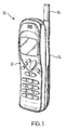
- a cellular telephone in accordance with the invention is shown in Figure 1 and is generally designated 10.
- the telephone 10 comprises a housing having a front casing 12 and a rear casing 14.
- An antenna 15 projects from the top of the rear casing 14.
- a single (rigid) printed circuit board 16 is provided within the housing.
- the main engine of the telephone is surface mounted to the circuit board and other ancillary electrical/electronic components are directly connected to it.
- FIG. 2 shows the rear casing 14 of the telephone 10.
- the front casing 12 of the telephone 10 has been completely omitted and an outline of the circuit board 16 is shown in dashed lines displaced from its normal position within the rear casing 14.
- the inside of the rear casing 14 may be thought of as being divided into a large first region 18 making up most of the internal area of the casing 14 and a small second region 20 in the vicinity of the antenna 15.
- a pair of spaced rests 22 are provided inside the second region 20, a pair of spaced rests 22 are provided.
- Each rest 22 comprises a pair of upstanding fingers 23 defining a generally U-shaped space or recess 23a therebetween.
- the general depth within the rear casing 14 of the first and second regions 18, 20 differs to an extent that if the circuit board 16 is placed in position, as indicated by arrows A, it rests on the large region 20 and covers the second region 18 while leaving a small clearance between the free ends of the fingers 23 and the lower surface of the circuit board 16.
- the rests 22 are intended to retain in position a headset socket 30.
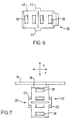
- the socket 30 is shown from various views in Figures 3 to 6.
- the socket 30 comprises a body 32 generally having the shape of a rectangular block.
- the body 32 includes an aperture 34 formed in its front face 36 for receiving the plug of a headset.
- the coupling of the headset plug within the socket 30 is conventional and so is not described here further, except to say that this coupling is communicated electrically from the socket 30 to the rest of the telephone by spring fingers 38.
- the spring fingers 38 upstand at an acute angle from the upper surface 40 of the body 32. In Figures 3 and 5, the spring fingers 38 are shown in their natural bias position. The spring fingers 38 can be depressed to lie flat against the upper surface 40 of the body 30.
- retaining protuberances or wings 44 are formed on opposed side surfaces 42 of the body 32.
- the retaining wings 44 are generally U-shaped and adapted to sit within the U-shaped spaces 23a defined by each rest 22.
- Figure 7 shows the socket 30 in this position. It will be noted from this drawing that the front face 36 of the body 30 stands flush with the outer surface of the casing 14.
- the socket 30 is placed into position by a pick-and-place machine.
- the dimensional tolerances of the retaining wings 44 and the rests 22 are selected to be compatible with the alignment accuracy of this process.
- the circuit board 16 is fitted within the rear casing 14 as illustrated by arrows A in Figure 2.
- Contact pads 50 on the underside (from the Figure 2 viewpoint) of the circuit board 16 as shown in dotted outline in Figure 2 each press against one of the spring fingers 38 to provide the electrical connection of the socket 30 with the circuit board 16.
- the socket 30 is subjected to forces in the y-direction.
- the socket 30 is substantially prevented from moving in this axis in both directions by virtue of the retaining wings 44 being confined between the fingers 23 of the rests 22.
- the engagement of the retaining wings 44 and the rests 22 bears the forces applied by the user and so these forces need not be borne by means for maintaining electrical contact with the circuit board.
- the body 32 of the socket being lodged between the rests 22 is confined in the x-direction too. Because of the above-mentioned dimensional tolerances between the retaining wings 44 and the rests 22, there can be some play between these co-operating parts.
- the fingers 38 are sprung and not fixed or joined, for example by solder, to the circuit board, the integrity/reliability of the electrical connection between the fingers 38 and the pads 50 is not impaired.
- the rear casing and the socket fit together with the socket supplying the male parts, i.e. the retaining wings 44, and the rear casing supplying the female parts, i.e. the rests 22 within which the retaining wings are held.
- the socket may be provided with female parts and the rear casing may be provided with male parts.
Landscapes
- Engineering & Computer Science (AREA)
- Signal Processing (AREA)
- Telephone Set Structure (AREA)
- Coupling Device And Connection With Printed Circuit (AREA)
- Mounting Components In General For Electric Apparatus (AREA)
- Connector Housings Or Holding Contact Members (AREA)
Claims (6)
- Prise pour casque d'écoute (30) comprenant un corps (32) et des contacts à ressort (38), et un moyen de retenue (44) adapté pour coopérer avec un moyen de retenue correspondant (22) sur un dispositif (10) dans lequel la prise pour casque d'écoute doit être montée pour supporter les contacts à ressort (38) en contact électrique avec les contacts électriques (50) du dispositif (10), caractérisée en ce que le moyen de retenue (44) de la prise (30) est agencé pour coopérer avec le moyen de retenue (22) du dispositif (10) pour permettre un déplacement sur un axe orthogonal à un plan étant parallèle à celui d'une carte de circuit imprimé (16) sur laquelle les contacts électriques (50) sont montés.
- Prise pour casque d'écoute (30) selon la revendication 1, dans laquelle le moyen de retenue (44) de la prise (30) est agencé pour coopérer avec le moyen de retenue (22) du dispositif (10) pour limiter le déplacement de la prise (30) sur ledit plan.
- Dispositif (10) comportant un boîtier dans lequel est placée une carte de circuit imprimé unique (16) sur laquelle des contacts électriques (50) sont montés, un moyen de retenue (22) et une prise pour casque d'écoute (30) selon l'une quelconque des revendications précédentes, le moyen de retenue (44) de la prise (30) coopérant avec le moyen de retenue (22) du dispositif (10) pour maintenir les contacts à ressort (38) en contact électrique avec les contacts électriques (50) de ladite manière.
- Dispositif (10) selon la revendication 3, dans lequel le moyen de retenue (44) de la prise (30) est agencé pour coopérer avec le moyen de retenue (22) du dispositif (10) pour limiter le déplacement sur des axes orthogonaux sur ledit plan.
- Dispositif (10) selon la revendication 3 ou 4, dans lequel le moyen de retenue (44) de la prise (30) comprend au moins un élément sur le corps de la prise pour casque d'écoute (30) étant l'un d'un élément mâle et d'un élément femelle et le moyen de retenue (22) du dispositif (10) comprend des éléments complémentaires sur le boîtier étant l'autre d'un élément mâle et d'un élément femelle.
- Dispositif (10) selon l'une quelconque des revendications 3 à 5, dans lequel le dispositif (10) est un téléphone sans fil.
Applications Claiming Priority (2)
| Application Number | Priority Date | Filing Date | Title |
|---|---|---|---|
| GB9725184 | 1997-11-28 | ||
| GB9725184A GB2331866B (en) | 1997-11-28 | 1997-11-28 | Radiotelephone |
Publications (3)
| Publication Number | Publication Date |
|---|---|
| EP0920167A2 EP0920167A2 (fr) | 1999-06-02 |
| EP0920167A3 EP0920167A3 (fr) | 2001-10-04 |
| EP0920167B1 true EP0920167B1 (fr) | 2007-03-14 |
Family
ID=10822785
Family Applications (1)
| Application Number | Title | Priority Date | Filing Date |
|---|---|---|---|
| EP98309318A Expired - Lifetime EP0920167B1 (fr) | 1997-11-28 | 1998-11-13 | Appareil muni d'une prise pour casque d'écoute |
Country Status (6)
| Country | Link |
|---|---|
| US (1) | US6597901B1 (fr) |
| EP (1) | EP0920167B1 (fr) |
| JP (1) | JP4067669B2 (fr) |
| DE (1) | DE69837315T2 (fr) |
| ES (1) | ES2283044T3 (fr) |
| GB (1) | GB2331866B (fr) |
Families Citing this family (4)
| Publication number | Priority date | Publication date | Assignee | Title |
|---|---|---|---|---|
| JP2001128278A (ja) | 1999-10-26 | 2001-05-11 | Matsushita Electric Ind Co Ltd | イヤホンジャック保持装置 |
| US7248864B1 (en) * | 2000-09-29 | 2007-07-24 | Palmsource, Inc. | System and method of managing incoming calls on a mobile device having an earplug |
| KR101923472B1 (ko) * | 2011-12-06 | 2018-11-29 | 엘지전자 주식회사 | 소켓 모듈 및 이를 구비한 단말기 |
| CN103633481A (zh) * | 2012-08-27 | 2014-03-12 | 深圳富泰宏精密工业有限公司 | 电连接器组件及具有该电连接器组件的电子装置 |
Family Cites Families (39)
| Publication number | Priority date | Publication date | Assignee | Title |
|---|---|---|---|---|
| US4037913A (en) * | 1975-02-13 | 1977-07-26 | Magnetic Controls Company | Printed circuit jack |
| US4392708A (en) * | 1980-08-04 | 1983-07-12 | Switchcraft, Inc. | Electrical jack |
| US4675903A (en) * | 1984-06-29 | 1987-06-23 | Wang Laboratories, Inc. | Telephone handset assembly |
| US4629278A (en) * | 1985-04-15 | 1986-12-16 | Amp Incorporated | Surface mountable connector retention means and method |
| US4706273A (en) * | 1985-11-14 | 1987-11-10 | Anthony P. Palett | Cellular telephone |
| CA1306025C (fr) * | 1988-02-15 | 1992-08-04 | Itt Industries Limited | Connecteurs pour conducteurs isoles |
| US5170494A (en) | 1988-12-08 | 1992-12-08 | Nokia Mobile Phones Ltd. | Two piece radio telephone |
| JPH0297771U (fr) * | 1989-01-17 | 1990-08-03 | ||
| FI85783C (fi) | 1989-02-17 | 1992-05-25 | Nokia Mobira Oy | Kylningskonstruktion foer transistor. |
| DE3910937C2 (de) * | 1989-04-01 | 1995-03-09 | Wago Verwaltungs Gmbh | Anreihbare Anschlußklemme für Leiterplatten |
| US5265158A (en) | 1989-05-25 | 1993-11-23 | Nokia Mobile Phones Ltd. | Construction of a stand alone portable telephone unit |
| US5256073A (en) * | 1989-06-13 | 1993-10-26 | General Datacomm, Inc. | Electrical connectors for direct connection to plated through holes in circuit board |
| FI88230C (fi) | 1990-04-12 | 1993-04-13 | Nokia Mobile Phones Ltd | Laddare foer batteridriven anordning |
| FI85204C (fi) | 1990-04-12 | 1992-03-10 | Nokia Mobile Phones Ltd | Konstruktion foer radiotelefon eller manoeveranordning till en radiotelefon. |
| FI85776C (fi) | 1990-08-20 | 1992-05-25 | Nokia Oy Ab | Transportabel personlig arbetsstation. |
| FI88244C (fi) | 1990-12-13 | 1993-04-13 | Nokia Mobile Phones Ltd | Jordad mellanstomme foer kretsskivor |
| US5199896A (en) * | 1991-07-29 | 1993-04-06 | Itt Corporation | Latchable p.c. board connector |
| FI94582C (fi) | 1992-01-23 | 1995-09-25 | Nokia Mobile Phones Ltd | Kiinnitin |
| US5338215A (en) * | 1993-03-19 | 1994-08-16 | Molex Incorporated | Jack assembly including a contact switching system |
| US5310360A (en) * | 1993-05-18 | 1994-05-10 | Molex Incorporated | Circuit board mounted modular phone jack |
| US5338230A (en) * | 1993-06-29 | 1994-08-16 | Molex Incorporated | Electrical connector assembly |
| US5557653A (en) * | 1993-07-27 | 1996-09-17 | Spectralink Corporation | Headset for hands-free wireless telephone |
| DE9317133U1 (de) * | 1993-11-09 | 1994-03-10 | Siemens AG, 80333 München | Steckaufnahme für eine Fernsprechstation |
| FI102805B (fi) | 1993-11-26 | 1999-02-15 | Nokia Mobile Phones Ltd | Matkapuhelimen rakenneratkaisu |
| FI107002B (fi) | 1994-01-13 | 2001-05-15 | Nokia Mobile Phones Ltd | Matkapuhelimen kädet vapaana- eli HF-laitteisto |
| FI98178C (fi) | 1994-04-19 | 1997-04-25 | Nokia Mobile Phones Ltd | Matkapuhelimen kortinlukijajärjestely |
| US5533908A (en) * | 1994-08-31 | 1996-07-09 | The Whitaker Corporation | Latch and mounting member for a surface mounted electrical connector |
| US5716230A (en) * | 1995-06-02 | 1998-02-10 | Molex Incorporated | Surface engageable electrical connector |
| FI107849B (fi) | 1995-06-30 | 2001-10-15 | Nokia Mobile Phones Ltd | Soviteosa matkaviestimessä sen kiinnityslaitetta varten |
| FI107850B (fi) | 1995-06-30 | 2001-10-15 | Nokia Mobile Phones Ltd | Kantoväline matkaviestimen kiinnityslaitetta varten |
| FI111309B (fi) | 1996-01-03 | 2003-06-30 | Nokia Corp | Tietoliikenneverkkoon radioteitse liitettävä päätelaite |
| GB9617178D0 (en) * | 1996-08-15 | 1996-09-25 | Amp Holland | Low height modular jack receptacle |
| US5768370A (en) | 1997-01-08 | 1998-06-16 | Nokia Mobile Phones, Ltd. | User changeable cosmetic phone interface |
| TW371120U (en) * | 1997-04-08 | 1999-09-21 | Hon Hai Prec Ind Co Ltd | Joint structure of plug |
| US5883787A (en) * | 1997-04-10 | 1999-03-16 | Ericsson, Inc. | Floating guided connector and method |
| US6315620B1 (en) * | 1997-04-24 | 2001-11-13 | Seagate Technology Llc | System, method, and device for a pre-loaded straddle mounted connector assembly |
| US6012949A (en) * | 1998-12-09 | 2000-01-11 | Hon Hai Precision Ind. Co., Ltd. | Electrical connector assembly and boardlocks thereof |
| US6089923A (en) * | 1999-08-20 | 2000-07-18 | Adc Telecommunications, Inc. | Jack including crosstalk compensation for printed circuit board |
| TW427561U (en) * | 1999-10-21 | 2001-03-21 | Hon Hai Prec Ind Co Ltd | Socket connector |
-
1997
- 1997-11-28 GB GB9725184A patent/GB2331866B/en not_active Expired - Fee Related
-
1998
- 1998-11-13 ES ES98309318T patent/ES2283044T3/es not_active Expired - Lifetime
- 1998-11-13 DE DE69837315T patent/DE69837315T2/de not_active Expired - Lifetime
- 1998-11-13 EP EP98309318A patent/EP0920167B1/fr not_active Expired - Lifetime
- 1998-11-23 US US09/197,867 patent/US6597901B1/en not_active Expired - Lifetime
- 1998-11-26 JP JP33589198A patent/JP4067669B2/ja not_active Expired - Lifetime
Also Published As
| Publication number | Publication date |
|---|---|
| US6597901B1 (en) | 2003-07-22 |
| GB2331866A (en) | 1999-06-02 |
| JPH11317800A (ja) | 1999-11-16 |
| DE69837315D1 (de) | 2007-04-26 |
| JP4067669B2 (ja) | 2008-03-26 |
| GB2331866B (en) | 2001-08-29 |
| DE69837315T2 (de) | 2007-12-20 |
| EP0920167A2 (fr) | 1999-06-02 |
| EP0920167A3 (fr) | 2001-10-04 |
| ES2283044T3 (es) | 2007-10-16 |
| GB9725184D0 (en) | 1998-01-28 |
Similar Documents
| Publication | Publication Date | Title |
|---|---|---|
| JP2889562B1 (ja) | スイッチ付き同軸コネクタ | |
| JP3377965B2 (ja) | 印刷配線板用コネクタ | |
| JP3477640B2 (ja) | コネクタ | |
| US8821191B2 (en) | Electrical connector assembly | |
| US7131875B2 (en) | Contact and electrical connector | |
| US8079864B2 (en) | Electronic apparatus having a cover which synchronously defined as a wall of a modular jack disposed thereof | |
| US6478630B1 (en) | Electrical card connector having polarization mechanism | |
| JP4010730B2 (ja) | カード保持構造およびそれを備えた携帯端末機 | |
| US20100055979A1 (en) | Electrical connector having improved terminals | |
| US20080045085A1 (en) | Electrical connector | |
| US6568963B2 (en) | Electrical connector assembly with improved contacts | |
| AU6473698A (en) | Floating guided connector and method | |
| US20050130510A1 (en) | Electrical card connector | |
| US7104820B1 (en) | Card connector with reliable signal transmission | |
| US7281943B1 (en) | Connector | |
| EP1453143A2 (fr) | Connecteur électrique avec contact de masse | |
| US7121864B1 (en) | Module connector | |
| JP2004127611A (ja) | 電気コネクタ | |
| US6597901B1 (en) | Device having a headset socket | |
| JP4247702B2 (ja) | カード保持装置およびそれを備えた携帯端末機 | |
| EP2020709A2 (fr) | Connecteur de carte électrique avec contacts améliorés | |
| US12519257B2 (en) | Electrical connector to achieve required coplanarity of terminal parts of receptacle, method for manufacturing electrical connector, and method for mounting electrical connector | |
| JP3718161B2 (ja) | 電子部品組立体及びそのためのユニット体 | |
| JP2004296419A (ja) | コネクタ | |
| KR100919950B1 (ko) | 심카드 커넥터 |
Legal Events
| Date | Code | Title | Description |
|---|---|---|---|
| PUAI | Public reference made under article 153(3) epc to a published international application that has entered the european phase |
Free format text: ORIGINAL CODE: 0009012 |
|
| AK | Designated contracting states |
Kind code of ref document: A2 Designated state(s): AT BE CH CY DE DK ES FI FR GB GR IE IT LI LU MC NL PT SE Kind code of ref document: A2 Designated state(s): DE ES FR SE |
|
| AX | Request for extension of the european patent |
Free format text: AL;LT;LV;MK;RO;SI |
|
| PUAL | Search report despatched |
Free format text: ORIGINAL CODE: 0009013 |
|
| AK | Designated contracting states |
Kind code of ref document: A3 Designated state(s): AT BE CH CY DE DK ES FI FR GB GR IE IT LI LU MC NL PT SE |
|
| AX | Request for extension of the european patent |
Free format text: AL;LT;LV;MK;RO;SI |
|
| RIC1 | Information provided on ipc code assigned before grant |
Free format text: 7H 04M 1/02 A, 7H 01R 23/72 B |
|
| RAP1 | Party data changed (applicant data changed or rights of an application transferred) |
Owner name: NOKIA CORPORATION |
|
| 17P | Request for examination filed |
Effective date: 20020404 |
|
| AKX | Designation fees paid |
Free format text: DE ES FR SE |
|
| GRAP | Despatch of communication of intention to grant a patent |
Free format text: ORIGINAL CODE: EPIDOSNIGR1 |
|
| GRAS | Grant fee paid |
Free format text: ORIGINAL CODE: EPIDOSNIGR3 |
|
| GRAA | (expected) grant |
Free format text: ORIGINAL CODE: 0009210 |
|
| AK | Designated contracting states |
Kind code of ref document: B1 Designated state(s): DE ES FR SE |
|
| RIC2 | Information provided on ipc code assigned after grant |
Ipc: H01R 12/22 20060101ALI20070205BHEP Ipc: H04M 1/02 20060101AFI20070205BHEP |
|
| REF | Corresponds to: |
Ref document number: 69837315 Country of ref document: DE Date of ref document: 20070426 Kind code of ref document: P |
|
| REG | Reference to a national code |
Ref country code: SE Ref legal event code: TRGR |
|
| ET | Fr: translation filed | ||
| REG | Reference to a national code |
Ref country code: ES Ref legal event code: FG2A Ref document number: 2283044 Country of ref document: ES Kind code of ref document: T3 |
|
| PLBE | No opposition filed within time limit |
Free format text: ORIGINAL CODE: 0009261 |
|
| STAA | Information on the status of an ep patent application or granted ep patent |
Free format text: STATUS: NO OPPOSITION FILED WITHIN TIME LIMIT |
|
| 26N | No opposition filed |
Effective date: 20071217 |
|
| PGFP | Annual fee paid to national office [announced via postgrant information from national office to epo] |
Ref country code: FR Payment date: 20101123 Year of fee payment: 13 |
|
| PGFP | Annual fee paid to national office [announced via postgrant information from national office to epo] |
Ref country code: SE Payment date: 20101111 Year of fee payment: 13 |
|
| REG | Reference to a national code |
Ref country code: SE Ref legal event code: EUG |
|
| REG | Reference to a national code |
Ref country code: FR Ref legal event code: ST Effective date: 20120731 |
|
| PG25 | Lapsed in a contracting state [announced via postgrant information from national office to epo] |
Ref country code: SE Free format text: LAPSE BECAUSE OF NON-PAYMENT OF DUE FEES Effective date: 20111114 |
|
| PG25 | Lapsed in a contracting state [announced via postgrant information from national office to epo] |
Ref country code: FR Free format text: LAPSE BECAUSE OF NON-PAYMENT OF DUE FEES Effective date: 20111130 |
|
| REG | Reference to a national code |
Ref country code: DE Ref legal event code: R082 Ref document number: 69837315 Country of ref document: DE Representative=s name: BECKER, KURIG, STRAUS, DE |
|
| REG | Reference to a national code |
Ref country code: DE Ref legal event code: R082 Ref document number: 69837315 Country of ref document: DE Representative=s name: BECKER, KURIG, STRAUS, DE Effective date: 20150312 Ref country code: DE Ref legal event code: R081 Ref document number: 69837315 Country of ref document: DE Owner name: NOKIA TECHNOLOGIES OY, FI Free format text: FORMER OWNER: NOKIA CORP., 02610 ESPOO, FI Effective date: 20150312 |
|
| REG | Reference to a national code |
Ref country code: ES Ref legal event code: PC2A Owner name: NOKIA TECHNOLOGIES OY Effective date: 20151124 |
|
| PGFP | Annual fee paid to national office [announced via postgrant information from national office to epo] |
Ref country code: DE Payment date: 20171108 Year of fee payment: 20 |
|
| PGFP | Annual fee paid to national office [announced via postgrant information from national office to epo] |
Ref country code: ES Payment date: 20171201 Year of fee payment: 20 |
|
| REG | Reference to a national code |
Ref country code: DE Ref legal event code: R071 Ref document number: 69837315 Country of ref document: DE |
|
| REG | Reference to a national code |
Ref country code: ES Ref legal event code: FD2A Effective date: 20200803 |
|
| PG25 | Lapsed in a contracting state [announced via postgrant information from national office to epo] |
Ref country code: ES Free format text: LAPSE BECAUSE OF EXPIRATION OF PROTECTION Effective date: 20181114 |