EP0920836B1 - Katheterspitzenelektrode mit mehreren Temperatursensoren - Google Patents
Katheterspitzenelektrode mit mehreren Temperatursensoren Download PDFInfo
- Publication number
- EP0920836B1 EP0920836B1 EP98309826A EP98309826A EP0920836B1 EP 0920836 B1 EP0920836 B1 EP 0920836B1 EP 98309826 A EP98309826 A EP 98309826A EP 98309826 A EP98309826 A EP 98309826A EP 0920836 B1 EP0920836 B1 EP 0920836B1
- Authority
- EP
- European Patent Office
- Prior art keywords
- wire
- tip
- tip electrode
- temperature sensors
- catheter
- Prior art date
- Legal status (The legal status is an assumption and is not a legal conclusion. Google has not performed a legal analysis and makes no representation as to the accuracy of the status listed.)
- Expired - Lifetime
Links
- 238000004891 communication Methods 0.000 claims description 2
- 239000003292 glue Substances 0.000 description 19
- WABPQHHGFIMREM-UHFFFAOYSA-N lead(0) Chemical compound [Pb] WABPQHHGFIMREM-UHFFFAOYSA-N 0.000 description 19
- 230000006835 compression Effects 0.000 description 15
- 238000007906 compression Methods 0.000 description 15
- 238000001802 infusion Methods 0.000 description 12
- 210000005003 heart tissue Anatomy 0.000 description 10
- 229920002635 polyurethane Polymers 0.000 description 9
- 239000004814 polyurethane Substances 0.000 description 9
- 125000006850 spacer group Chemical group 0.000 description 9
- 239000000463 material Substances 0.000 description 8
- 239000004642 Polyimide Substances 0.000 description 6
- 229920001721 polyimide Polymers 0.000 description 6
- 229910001220 stainless steel Inorganic materials 0.000 description 6
- 239000010935 stainless steel Substances 0.000 description 6
- 238000010276 construction Methods 0.000 description 5
- 229910052751 metal Inorganic materials 0.000 description 5
- 239000002184 metal Substances 0.000 description 5
- RYGMFSIKBFXOCR-UHFFFAOYSA-N Copper Chemical compound [Cu] RYGMFSIKBFXOCR-UHFFFAOYSA-N 0.000 description 4
- 238000013461 design Methods 0.000 description 4
- 239000012530 fluid Substances 0.000 description 4
- 239000004033 plastic Substances 0.000 description 4
- 229920003023 plastic Polymers 0.000 description 4
- 229920006362 Teflon® Polymers 0.000 description 3
- 238000002679 ablation Methods 0.000 description 3
- 229910000679 solder Inorganic materials 0.000 description 3
- 229910001006 Constantan Inorganic materials 0.000 description 2
- 239000008280 blood Substances 0.000 description 2
- 210000004369 blood Anatomy 0.000 description 2
- 239000011248 coating agent Substances 0.000 description 2
- 238000000576 coating method Methods 0.000 description 2
- 238000001035 drying Methods 0.000 description 2
- -1 i.e. Polymers 0.000 description 2
- 238000000034 method Methods 0.000 description 2
- 238000012546 transfer Methods 0.000 description 2
- 229920001651 Cyanoacrylate Polymers 0.000 description 1
- 229910018487 Ni—Cr Inorganic materials 0.000 description 1
- 239000004677 Nylon Substances 0.000 description 1
- FAPWRFPIFSIZLT-UHFFFAOYSA-M Sodium chloride Chemical compound [Na+].[Cl-] FAPWRFPIFSIZLT-UHFFFAOYSA-M 0.000 description 1
- 239000004830 Super Glue Substances 0.000 description 1
- 230000004075 alteration Effects 0.000 description 1
- 238000004873 anchoring Methods 0.000 description 1
- 238000005452 bending Methods 0.000 description 1
- 238000009529 body temperature measurement Methods 0.000 description 1
- 210000005242 cardiac chamber Anatomy 0.000 description 1
- 239000000919 ceramic Substances 0.000 description 1
- ZTXONRUJVYXVTJ-UHFFFAOYSA-N chromium copper Chemical compound [Cr][Cu][Cr] ZTXONRUJVYXVTJ-UHFFFAOYSA-N 0.000 description 1
- VNNRSPGTAMTISX-UHFFFAOYSA-N chromium nickel Chemical compound [Cr].[Ni] VNNRSPGTAMTISX-UHFFFAOYSA-N 0.000 description 1
- 230000015271 coagulation Effects 0.000 description 1
- 238000005345 coagulation Methods 0.000 description 1
- 238000007796 conventional method Methods 0.000 description 1
- 238000002788 crimping Methods 0.000 description 1
- 210000003298 dental enamel Anatomy 0.000 description 1
- 239000003814 drug Substances 0.000 description 1
- 229940079593 drug Drugs 0.000 description 1
- 238000005516 engineering process Methods 0.000 description 1
- 238000004880 explosion Methods 0.000 description 1
- 238000010438 heat treatment Methods 0.000 description 1
- 230000003902 lesion Effects 0.000 description 1
- 210000004165 myocardium Anatomy 0.000 description 1
- 229910001000 nickel titanium Inorganic materials 0.000 description 1
- HLXZNVUGXRDIFK-UHFFFAOYSA-N nickel titanium Chemical compound [Ti].[Ti].[Ti].[Ti].[Ti].[Ti].[Ti].[Ti].[Ti].[Ti].[Ti].[Ni].[Ni].[Ni].[Ni].[Ni].[Ni].[Ni].[Ni].[Ni].[Ni].[Ni].[Ni].[Ni].[Ni] HLXZNVUGXRDIFK-UHFFFAOYSA-N 0.000 description 1
- 231100000252 nontoxic Toxicity 0.000 description 1
- 230000003000 nontoxic effect Effects 0.000 description 1
- 229920001778 nylon Polymers 0.000 description 1
- 239000006223 plastic coating Substances 0.000 description 1
- 230000001681 protective effect Effects 0.000 description 1
- 239000011780 sodium chloride Substances 0.000 description 1
- 239000007787 solid Substances 0.000 description 1
- 210000001519 tissue Anatomy 0.000 description 1
- 230000007704 transition Effects 0.000 description 1
- 230000000007 visual effect Effects 0.000 description 1
Images



Classifications
-
- A—HUMAN NECESSITIES
- A61—MEDICAL OR VETERINARY SCIENCE; HYGIENE
- A61B—DIAGNOSIS; SURGERY; IDENTIFICATION
- A61B18/00—Surgical instruments, devices or methods for transferring non-mechanical forms of energy to or from the body
- A61B18/04—Surgical instruments, devices or methods for transferring non-mechanical forms of energy to or from the body by heating
- A61B18/12—Surgical instruments, devices or methods for transferring non-mechanical forms of energy to or from the body by heating by passing a current through the tissue to be heated, e.g. high-frequency current
- A61B18/14—Probes or electrodes therefor
- A61B18/1492—Probes or electrodes therefor having a flexible, catheter-like structure, e.g. for heart ablation
Definitions
- the present invention relates to an ablation catheter having a tip electrode containing multiple temperature sensors at predetermined locations within the tip electrode.
- Ablation catheters typically have a tip electrode at their distal end for ablating the heart tissue. Temperature sensors are used to monitor the temperature of the tip electrode in contact with the heart tissue to assist the physician in determining whether the tip electrode is too hot. When the tip electrode becomes too hot, coagulation forms on the tip electrode, causing a steam explosion in the heart tissue.
- Typical tip electrodes have a length of approximately 4 mm. In certain applications, e.g., when longer lesions are desired, longer tip electrodes are preferred. When longer tip electrodes are used, e.g., around 8 mm to 12 mm, accurately determining the temperature of the electrode in contact with the heart tissue becomes more difficult.
- the temperature of the tip electrode will vary across its surface, e.g., depending on whether the surface is in contact with myocardium or circulating blood. Consequently, if a single temperature sensor is used, it may be at a location within the tip electrode remote from the portion of the tip electrode in contact with the heart tissue. If that sensor is adjacent a portion of the tip electrode in contact with rapidly circulating blood, it may provide a temperature reading which is not indicative of the portion of the tip electrode that is in contact with the heart tissue. Thus, it is desirable to place multiple temperature sensors along the length of the tip electrode to more accurately monitor the temperature of the portion of the tip electrode in contact with the heart tissue.
- the temperature sensor will be as close as possible to the surface of the tip electrode in contact with the heart tissue.
- placement of a temperature sensor on one side of the tip electrode will provide erroneous temperature readings if the opposite side of the electrode is in contact with the heart tissue. Therefore, it is generally preferred that temperature sensors be located along the axis of the tip electrode.
- the temperature of the tip electrode is typically controlled by an RF generator having a feedback control circuit.
- the generator receives signals from the temperature sensor and supplies more or less RF energy to the tip electrode depending on the signal received. When multiple temperature sensors are used, the generator uses as a control the temperature sensor measuring the fastest temperature change.
- the present invention provides a steerable catheter particularly useful in ablation procedures having at least two temperature sensors within a tip electrode at predetermined, spaced-apart locations, preferably along the axis of the tip electrode.
- the catheter comprises a catheter body, a tip section attached to the distal end of the catheter body and a control handle attached to the proximal end of the catheter body.
- the tip section has at least one lumen and a tip electrode fixedly attached at its distal end.
- the tip electrode has a blind hole, preferably a blind axial hole, extending along a portion of its length in communication with the lumen in the tip section.
- An anchor wire extends into the blind hole of the tip electrode and carries at least two temperature sensors fixedly attached along its length. The temperature sensors are fixedly attached at predetermined, spaced-apart locations along the length of the anchor wire so that the physician knows their location and the distance between them.
- thermocouples Preferred temperature sensors are thermocouples.
- a particularly preferred thermocouples comprises a double-stranded enameled wire pair comprising a copper wire, e.g., a number 40 copper wire, and a construction wire, e.g., a constantan wire, which gives support and strength to the wire pair.
- a construction wire e.g., a constantan wire, which gives support and strength to the wire pair.
- the enamel is removed, and the wires are twisted and welded to the anchor wire.
- the wires are connected at their proximal ends to a temperature monitor.
- the anchor wire is also used as a puller wire.
- a puller wire is attached at its proximal end to the control handle and extends through a lumen in the catheter body and an off-axis lumen in the tip section to the tip electrode. Manipulation of the control handle results in lengthwise movement of the puller wire relative to the catheter body and deflection of the tip section.
- the puller wire comprises a ferrule fixedly attached at its distal end.
- Multiple temperature sensors are fixedly attached at designated locations along the length of the ferrule, which is soldered or otherwise fixedly attached inside the blind hole in the tip electrode.
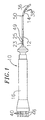
- the catheter 10 comprises an elongated catheter body 12 having proximal and distal ends, a deflectable tip section 14 at the distal end of the catheter body 12 , and a control handle 16 at the proximal end of the catheter body 12
- the catheter body 12 comprises an elongated tubular construction having a single, central lumen 18 .
- the catheter body 12 is flexible, i.e., bendable, but substantially non-compressible along its length.
- the catheter body 12 can be of any suitable construction and made of any suitable material.
- a presently preferred construction comprises an outer wall 22 made of polyurethane or nylon.
- the outer wall 22 comprises an imbedded braided mesh of stainless steel or the like to increase torsional stiffness of the catheter body 12 so that, when the control handle 16 is rotated, the tip section 14 of the catheter 10 will rotate in a corresponding manner.
- the outer diameter of the catheter body 12 is not critical, but is preferably no more than about 2.64 mm (8 french) Likewise the thickness of the outer wall 22 is not critical.
- the inner surface of the outer wall 22 is lined with a stiffening tube 20 , which can be made of any suitable material, preferably polyimide.
- the stiffening tube 20 along with the braided outer wall 22 , provides improved torsional stability while at the same time minimizing the wall thickness of the catheter body 12 , thus maximizing the diameter of the central lumen 18 .
- the outer diameter of the stiffening tube 20 is about the same as or slightly smaller than the inner diameter of the outer wall 22 .
- Polyimide tubing is presently preferred because it may be very thin walled while still providing very good stiffness.
- a particularly preferred catheter has an outer wall 22 with an outer diameter of about 2-31 mm (0.091 inch) and an inner diameter of about 1.60 mm (0.063 inch) and a stiffening tube 20 having an outer diameter of about 1.52 mm (0.060 inch) and an inner diameter of about 0.94 mm (0.037 inch).
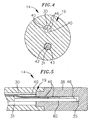
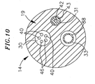
- the tip section 14 comprises a short section of tubing 19 having two off-axis tip lumens 30 and 31 .
- the tubing 19 is made of a suitable non-toxic material that is preferably more flexible than the catheter body 12 .
- a presently preferred material for the tubing 19 is braided polyurethane, i.e., polyurethane with an embedded mesh of braided stainless steel or the like.
- the outer diameter of the tip section 14 like that of the catheter body 12 , is preferably no greater than about 2.64 mm (8 french).
- the sizes of the tip lumens 30 and 31 are not critical. In a particularly preferred embodiment, the tip section 14 has an outer diameter of about 2.31 mm (7 french) (.092 inch) and the two tip lumens 30 and 31 are generally about the same size, each having a diameter of about 0.51 mm (0.020 inch).
- FIG. 2 A preferred means for attaching the catheter body 12 to the tip section 14 is illustrated in FIG. 2.
- the proximal end of the tip section 14 comprises an outer circumferential notch 24 that receives the inner surface of the outer wall 22 of the catheter body 12 .
- the tip section 14 and catheter body 12 are attached by glue or the like.
- a spacer 32 lies within the catheter body 12 between the distal end of the stiffening tube 20 and the proximal end of the tip section 14 .
- the spacer 32 is preferably made of a material that is stiffer than the material of the tip section 14 , e.g., polyurethane, but not as stiff as the material of the stiffening tube 20 , e.g., polyimide.
- a spacer 32 made of Teflon® is presently preferred.
- a preferred spacer 32 has a length of from about 6.35 mm (0.25 inch) to about 19.1 mm (0.75 inch) more preferably about 12.7 mm (0.5 inch).
- Preferably the spacer 32 has an outer and inner diameter about the same as the outer and inner diameters of the stiffening tube 20 .
- the spacer 32 provides a transition in flexibility at the junction of the catheter body 12 and catheter tip 14 , allowing the junction of the catheter body 12 and tip section 14 to bend smoothly without folding or kinking.
- the spacer 32 is held in place by the stiffening tube 20 .
- the stiffening tube 20 is held in place relative to the outer wall 22 by glue joints 23 and 25 at the proximal end of the catheter body 12 .
- a force is applied to the proximal end of the stiffening tube 20 , causing the distal end of the stiffening tube 20 to firmly butt up against and compress the spacer 32 .
- a first glue joint 23 is made between the stiffening tube 20 and the outer wall 22 by a fast drying glue, e.g. Super Glue®.
- a second glue joint 25 is formed between the proximal ends of the stiffening tube 20 and outer wall 22 using a slower drying but stronger glue, e.g., polyurethane.
- a tip electrode 36 At the distal end of the tip section 14 is a tip electrode 36 .
- the proximal end of the tip electrode 36 has a circumferential notch 37 that fits inside the distal end of the tip section 14 .
- the proximal end of the tip electrode 36 is bonded to the tip section 14 by polyurethane glue or the like.
- the tip electrode 36 has a generally cylindrical shape with a rounded distal end, but may have any shape as desired as is well-known in the art. Preferably the tip electrode 36 has a diameter about the same as the outer diameter of the tubing 19 .
- the tip electrode 36 has an exposed length, i.e., outside the plastic tubing 19 of the tip section 14 , preferably of from about 3 mm to about 12 mm, more preferably of from about 6 mm to about 10 mm, still more preferably of about 8 mm.
- the tip electrode 36 is generally solid with a blind hole 35 extending from its proximal end through most of its length.
- the blind hole 35 extends though at least about 50 percent of the length of the tip electrode, and more preferably at least about 85 percent of the length of the tip electrode.
- the diameter of the blind hole 35 preferably ranges from about 0.38 mm (0.015 inch) to about 0.76 mm (0.030 inch)
- the blind hole 35 extends along the axis of the tip electrode 36, but can extend off-axis if desired.
- the tip section 14 carries one or more ring electrodes 38 .
- the length of each ring electrode 38 is not critical, but is preferably about 1 mm to about 4 mm.
- the ring electrodes 38 are spaced apart a distance of about 2 mm to about 4 mm.
- the tip electrode 36 and ring electrodes 38 are each connected to a separate lead wire 40 .
- the lead wires 40 extend through the first tip lumen 30 of tip section 14 , the central lumen 18 of the catheter body 12 , and the control handle 16 , and terminate at their proximal end in an input jack (not shown) that may be plugged into an appropriate monitor (not shown). If desired, the portion of the lead wires 40 extending through the catheter body 12 , control handle 16 and proximal end of the tip section 14 may be enclosed or bundled within a protective tube or sheath (not shown).
- the lead wires 40 are attached to the tip electrode 36 and ring electrodes 38 by any conventional technique. Connection of a lead wire 40 to the tip electrode 36 is preferably accomplished by weld or the like, with the lead wire 40 wrapped around the proximal end of the tip electrode 36 within the plastic tubing 19 .
- Connection of a lead wire 40 to a ring electrode 38 is preferably accomplished by first making a small hole through the tubing 19 of the tip section 14 .
- a hole can be created, for example, by inserting a needle through the tubing 19 and heating the needle sufficiently to form a permanent hole.
- a lead wire 40 is then drawn through the hole by using a microhook or the like.
- the ends of the lead wire 40 are then stripped of any coating and soldered or welded to the underside of the ring electrode 38 , which is then slid into position over the hole and fixed in place with polyurethane glue or the like.
- a puller wire extends through the central lumen 18 in the catheter body 12.
- the puller wire is anchored at its proximal end to the control handle 16 and anchored at its distal end in the tip section 14 .
- the puller wire comprises an elongated wire 42 and a ferrule 34 at the distal end of the wire 42 .
- the wire 42 is made of any suitable metal, such as stainless steel or Nitinol, and is preferably coated with Teflon® or the like. The coating imparts lubricity to the wire 42 .
- the wire 42 preferably has a diameter of from about 0.15 mm (0.006 inch) to about 0.25 mm (0.010 inch)
- the wire 42 extends into the second tip lumen 31 and is anchored in the blind hole 35 of the tip electrode 36 . Withing the second tip lumen 31 , the wire 42 extends through a plastic, preferably Teflon®, sheath 43 , which prevents the wire 42 from cutting into the tubing 19 of the tip section 14 when the tip section is deflected.
- the ferrule 34 adds thickness to the distal end of the puller wire, providing more surface area for the puller wire to be soldered into the blind hole 35 of the tip electrode 36.
- the ferrule 34 is made of stainless steel, but can also be made of any other suitable metal, ceramic or plastic. When made of metal, the ferrule 34 is preferably crimped on the wire 42 .
- the distal end of the puller wire including ferrule 34 , preferably has an outer diameter ranging from about 0.51 mm (0.020 inch) to about 0.69 mm (0.027 inch, more preferably about 0.56 mm (0.022 inch).
- the ferrule 34 has a length slightly longer (e.g., about 1 to 2 mm) than the length of the blind hole 35 in the tip electrode 36 so that the proximal end of the ferrule extends into the tubing 19 of the tip section 14 .
- At least two temperature sensors are provided for the tip electrode 36 and are situated within the blind hole 35 of the tip electrode 36 .
- a preferred temperature sensor comprises a thermocouple 46 , but other temperature sensors, such as thermistors, could also be used.
- a preferred thermocouple is formed by a double-stranded enameled wire pair.
- One wire of the wire pair is a copper wire, e.g., a number 40 copper wire.
- the other wire of the wire pair is a constantan wire, which gives support and strength to the wire pair.
- the wires of the wire pair are electrically isolated from each other except at their distal ends where they contact the tip electrode 36 .
- thermocouple any other suitable thermocouple could also be used, for example, a wire pair comprising a nickel chromium wire and a chromium copper wire.
- a suitable thermistor for use with the present invention is Model No. AB6N2-GC14KA143E/37C sold by Thermometrics (New Jersey).
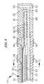
- each thermocouple 46 is welded or otherwise fixedly attached, e.g., with solder or glue, to the ferrule 34 of the puller wire 42 .
- one thermocouple 46a is anchored at the distal end of the ferrule 34 while the other thermocouple 46b is anchored near the midpoint of the ferrule 34 .
- the distance between the thermocouples 46 is between about 40 percent and 60 percent of the length of the blind hole 35 in the tip section 36 , more preferably about 50 percent of the length of the blind hole 35 .
- the distal end of the puller wire 42 containing the ferrule 34 and thermocouples 46 is soldered into the blind hole 35 in the tip section 36 .
- the tip electrode 36 is heated and the distal end of the puller wire 42 containing the ferrule 34 is placed inside the blind hole 35 . Solder is wicked into the blind hole 35 until full, then the tip electrode 36 is taken off the heat source. Preferably the entire blind hole 35 is filled with solder.
- thermocouples 46 extend out the blind hole 35 of the tip electrode 36 and into the first tip lumen 30 , through the central lumen 18 of the catheter body 12 , through the catheter handle 16 and to a connector (not shown) connectable to a temperature monitor (not shown).
- thermocouples 46 When more than two thermocouples 46 are mounted on the distal end of the puller wire they are preferably equally spaced, i.e., mounted approximately equal distances from each other. For example, when the exposed section of the tip electrode 36 is 8 mm, the distance between the thermocouples 46 on the distal end of the puller wire is approximately 4 mm. Preferably, one thermocouple 46 is fixedly attached at or near the distal end of the ferrule 34 .
- a compression coil 44 extends from the proximal end of the catheter body 12 to the proximal end of the tip section 14 in surrounding relation to the puller wire 42 .
- the compression coil 44 is made of any suitable metal, preferably stainless steel.
- the compression coil 44 is tightly wound on itself to provide flexibility, i.e., bending, but to resist compression.
- the inner diameter of the compression coil 44 is preferably slightly larger than the diameter of the puller wire 42 .
- the plastic coating on the puller wire 42 allows it to slide freely within the compression coil 44 .
- the outer surface of the compression coil 44 is covered by a flexible, non-conductive sheath 26 to prevent contact between the compression coil 44 and the lead wires 40 within the central lumen 18 of the catheter body 12 .
- a non-conductive sheath 26 made of polyimide tubing is presently preferred.
- the compression coil 44 is anchored at its proximal end to the proximal end of the stiffening tube 20 in the catheter body 12 by a glue joint 49 and at its distal end to the tip section 14 at a location distal to the spacer 32 by a glue joint 50 .
- Both glue joints 49 and 50 preferably comprise polyurethane glue or the like.
- the glue may be applied by means of a syringe or the like through a hole made between the outer surface of the catheter body 12 and the single lumen 18 . Such a hole may be formed, for example, by a needle or the like that punctures the outer wall 18 of the catheter body 12 and the stiffening tube 20 and that is heated sufficiently to form a permanent hole.
- the glue is then introduced through the hole to the outer surface of the compression coil 44 and wicks around the outer circumference to form a glue joint about the entire circumference of the compression coil 44 .
- the compression coil 44 can be anchored at its distal end to the distal end of the catheter body 12 .
- the compression coil 44 can be anchored directly to the outer wall 22 of the catheter body 12 .
- the electrode lead wires 40 and thermocouples 46 must be allowed some longitudinal movement within the catheter body 12 so that they do not break when the tip section 14 is deflected. To provide for such lengthwise movement, there are provided tunnels through the glue joints 49 and 50 , through which the lead wires 40 and thermocouples 46 extend to avoid contact with the glue.
- the tunnels are formed by transfer tubes 28 , preferably made of short segments of polyimide tubing. Each transfer tube is approximately 60 mm long and has an outer diameter of about 0.53 mm (.021 inch) and an inner diameter of about 0.48 mm (.019 inch).
- an anchor wire 80 which is not used as a puller wire, is provided to locate the temperature sensors within the blind hole 35 of the tip electrode 36 .
- the anchor wire 80 preferably has a diameter of from about 0.51 mm (0.020 inch) to about 0.69 mm (0.027 inch). If desired, the anchor wire 80 may have a smaller diameter and a ferrule, as described above, can be crimped on the outside of the anchor wire to increase the surface area of the anchor wire.
- the anchor wire 80 has a length preferably slightly longer (e.g., 1 mm to 2 mm) than the length of the blind hole 35 of the tip electrode 36 .
- At least two temperature sensors are mounted along the length of the anchor wire 80 .
- three thermocouples 46 are mounted along the length of the anchor wire 80 .
- the anchor wire 80 is then soldered into the blind hole 35 of the tip electrode 36 , preferably along the entire length of the blind hole in a manner similar to that described above.
- the puller wire 42 is anchored to the side of the tip section 14 rather than in the tip electrode 36 .
- a preferred means for anchoring the puller wire 42 to the side of the tip section 14 is shown in FIGs. 6 to 8.
- An anchor is formed by a metal tube 82 , e.g., a short segment of hypodermic stock, that is fixedly attached, e.g., by crimping, to the distal end of the puller wire 42 .
- the tube 82 has a section that extends a short distance beyond the distal end of the puller wire 42 .
- a cross-piece 84 made of a small section of stainless steel ribbon or the like is soldered or welded in a transverse arrangement to the distal end of the tube 82, which is flattened during the operation. This creates a T-bar anchor 81 .
- a notch 86 is created in the side of the tip section 14 resulting in an opening into the second tip lumen 31 carrying the puller wire 42 .
- the T-bar anchor 81 lies within the notch 86 . Because the length of the ribbon forming the cross-piece 84 is longer than the diameter of the opening into the second tip lumen 31 , the anchor 81 cannot be pulled completely into the second tip lumen 31 .
- the notch 86 is then sealed with polyurethane or the like to give a smooth outer surface.
- an infusion tube 88 for infusing fluids, including drugs and saline.
- the infusion tube 88 may also be used for collecting tissue or fluid samples.
- the infusion tube 88 may be made of any suitable material, and is preferably made of polyimide tubing.
- the catheter 88 comprises a single lumen catheter body 12 as described above and a tip section 14 comprising three tip lumens 30, 31 and 33 .
- the first tip lumen 30 and second tip lumen 31 are similar in size, having a diameter of about 0.51 mm (0.020 inch) and the third tip lumen. 33 is slightly larger, having a diameter of about 0.89 mm (0.035 inch)
- the infusion tube 88 extends through the catheter body 12 and into the third tip lumen 33 .
- the distal end of the infusion tube 88 extends into a passage 90 through the tip electrode 36 , which is different from the blind hole 35 .
- the infusion tube 88 is fixed, e.g., by glue, to the inside of the tip electrode 36 .
- the passage 90 in the tip electrode 36 may be straight or branched as desired.
- the passage 90 terminates in one or more radial or transverse holes 92 in the tip electrode 36 through which fluids can pass.
- the transverse holes 92 extend from the passage to the circumference of the tip electrode 36 .
- Preferably the transverse holes 92 are near the distal end of the tip electrode 36 . Any other design that allows fluids to flow from the passage into the heart, i.e., a porous tip electrode or a passage that extends out the distal end of the tip electrode, is also included within the scope of the invention.
- the proximal end of the infusion tube 88 extends out of a sealed opening in the side wall of the catheter body 12 and terminates in a luer hub or the like.
- the infusion tube 88 may extend through the control handle 16 and terminate in a luer hub or the like at a location proximal to the control handle.
- the infusion tube 88 extends only through the passage 90 in the tip electrode 36 and the distal end of the third lumen 33 .
- a second infusion tube 89 then extends from the proximal end of the third lumen 33 and through the catheter body 12 , and exits the catheter either through the side of the catheter body or out the proximal end of the control handle 16 .
- the blind hole 35 is an axial blind hole, i.e., extends along the axis of the tip electrode 36 . This reduces the risk of erroneous temperature readings, for example, if the temperature sensors are located opposite the side of the tip electrode 36 that is in contact with the heart tissue.
- the blind hole 35 extends off-axis.
- an electromagnetic sensor can be mounted within the tip section 14 .
- An electromagnetic sensor allows a physician to create a visual representation of the heart chamber and to view the location of the sensor, and therefore the catheter tip, within the chamber.
- a catheter incorporating an electromagnetic sensor is described, for example, in U.S. Patent Application Serial No. 08/924,623.
- Suitable electromagnetic sensor for use with the present invention are described, for example, in U.S. Patent Nos. 5,558,091, 5,443,489, 5,480,422, 5,546,951, and 5,568,809 and International Publication Nos.
- the puller wire and attached temperature sensors can extend into an off-axis blind hole in the tip electrode.
- the temperature sensors can be mounted on an anchor wire in an axial blind hole where the anchor wire extends only a short distance into the distal end of the tip section.
- two or more puller wires are provided to enhance the ability to manipulate the tip section.
- a second puller wire and a surrounding second compression coil extend through the catheter body and into an additional off-axis lumen in the tip section.
- the first puller wire is preferably anchored proximal to the anchor location of the second puller wire.
- the second puller wire may be anchored to the wall of the tip section.
- the tip electrode has a blind hole for each puller wire that extends into the tip electrode.
- Two or more temperature sensors are mounted on each puller wire that extends into the tip electrode. For example, if four puller wires are mounted the tip electrode, four blind holes are provided in the four quadrants of the tip electrode. Temperature measurements can then be taken at different locations near the edge of the tip electrode rather than along the axis.
- the present invention can be used in non-steerable catheters.
- an anchor wire with multiple temperature sensors is mounted within a blind hole in the tip electrode and no puller wire is necessary.
Landscapes
- Health & Medical Sciences (AREA)
- Life Sciences & Earth Sciences (AREA)
- Surgery (AREA)
- Engineering & Computer Science (AREA)
- Plasma & Fusion (AREA)
- Medical Informatics (AREA)
- Otolaryngology (AREA)
- Physics & Mathematics (AREA)
- Cardiology (AREA)
- Biomedical Technology (AREA)
- Heart & Thoracic Surgery (AREA)
- Nuclear Medicine, Radiotherapy & Molecular Imaging (AREA)
- Molecular Biology (AREA)
- Animal Behavior & Ethology (AREA)
- General Health & Medical Sciences (AREA)
- Public Health (AREA)
- Veterinary Medicine (AREA)
- Media Introduction/Drainage Providing Device (AREA)
- Surgical Instruments (AREA)
Claims (9)
- Katheter (10) umfassend:einen Katheterkörper (12) mit einem proximalen und einem distalen Ende und wenigstens einem Hohlraum (18), der sich dadurch erstreckt;einen Bedienungsgriff (16) am proximalen Ende des Katheterkörpers;einen Spitzenabschnitt (14) mit einem proximalen und einem distalen Ende und wenigstens einem Lumen (30; 31) dadurch, wobei das proximale Ende des Spitzenabschnittes fest mit dem distalen Ende des Katheterkörpers verbunden ist;eine Spitzenelektrode (36), die fest mit dem distalen Ende des Spitzenabschnittes verbunden ist, wobei die Spitzenelektrode ein Blindloch (35) in Verbindung mit einem Hohlraum in dem Spitzenabschnitt aufweist; undeinen Ankerdraht (42; 80) mit einem proximalen Ende und einem distalen Ende, der sich in das Blindloch der Spitzenelektrode erstreckt, dadurch gekennzeichnet, dass wenigstens zwei Temperatursensoren (46) fest entlang der Länge des Ankerdrahtes (42) befestigt sind.
- Katheter nach Anspruch 1, wobei die Entfernung zwischen den Temperatursensoren (46) von etwa 40 Prozent bis etwa 60 Prozent der Länge des Blindloches (35) beträgt.
- Katheter nach Anspruch 1, wobei die Entfernung zwischen den Temperatursensoren (46) etwa 50 Prozent der Länge des Blindloches (35) beträgt.
- Katheter nach Anspruch 1, wobei mehr als zwei Temperatursensoren (46) fest entlang der Länge des Drahtes (42; 48) befestigt sind.
- Katheter nach Anspruch 4, wobei die Temperatursensoren (46) entlang der Länge des Drahtes (42; 80) mit gleichem Abstand räumlich getrennt sind.
- Katheter nach einem der vorangehenden Ansprüche, wobei wenigstens einer der Temperatursensoren ein Thermoelement (46) umfasst.
- Katheter nach einem der vorangehenden Ansprüche, wobei ein jeder der Temperatursensoren ein Thermoelement (46) umfasst.
- Katheter nach einem der vorangehenden Ansprüche, wobei der Draht ein Zugdraht (42) mit einem proximalen und einem distalen Ende ist, und wobei sich der Zugdraht durch einen Hohlraum (31) in dem Spitzenabschnitt (14) und durch den Bedienungsgriff (16) erstreckt und an seinem proximalen Ende in dem Bedienungsgriff verankert ist, wobei die Betätigung des Bedienungsgriffes zu einer Bewegung des Zugdrahtes in Längsrichtung relativ zu dem Katheterkörper (12) und Ablenken des Spitzenabschnittes (14) führt.
- Katheter nach Anspruch 8, wobei der Zugdraht (42) eine an seinem distalen Ende fest befestigte Zwinge (34) umfasst.
Applications Claiming Priority (2)
| Application Number | Priority Date | Filing Date | Title |
|---|---|---|---|
| US982667 | 1997-12-02 | ||
| US08/982,667 US5935124A (en) | 1997-12-02 | 1997-12-02 | Tip electrode with multiple temperature sensors |
Publications (3)
| Publication Number | Publication Date |
|---|---|
| EP0920836A2 EP0920836A2 (de) | 1999-06-09 |
| EP0920836A3 EP0920836A3 (de) | 1999-08-11 |
| EP0920836B1 true EP0920836B1 (de) | 2004-06-09 |
Family
ID=25529399
Family Applications (1)
| Application Number | Title | Priority Date | Filing Date |
|---|---|---|---|
| EP98309826A Expired - Lifetime EP0920836B1 (de) | 1997-12-02 | 1998-12-01 | Katheterspitzenelektrode mit mehreren Temperatursensoren |
Country Status (4)
| Country | Link |
|---|---|
| US (1) | US5935124A (de) |
| EP (1) | EP0920836B1 (de) |
| JP (1) | JP4118423B2 (de) |
| DE (1) | DE69824373T2 (de) |
Families Citing this family (80)
| Publication number | Priority date | Publication date | Assignee | Title |
|---|---|---|---|---|
| US5810802A (en) | 1994-08-08 | 1998-09-22 | E.P. Technologies, Inc. | Systems and methods for controlling tissue ablation using multiple temperature sensing elements |
| US6723063B1 (en) | 1998-06-29 | 2004-04-20 | Ekos Corporation | Sheath for use with an ultrasound element |
| US6042580A (en) | 1998-05-05 | 2000-03-28 | Cardiac Pacemakers, Inc. | Electrode having composition-matched, common-lead thermocouple wire for providing multiple temperature-sensitive junctions |
| US6312425B1 (en) * | 1998-05-05 | 2001-11-06 | Cardiac Pacemakers, Inc. | RF ablation catheter tip electrode with multiple thermal sensors |
| US7137980B2 (en) | 1998-10-23 | 2006-11-21 | Sherwood Services Ag | Method and system for controlling output of RF medical generator |
| US6371955B1 (en) * | 1999-08-10 | 2002-04-16 | Biosense Webster, Inc. | Atrial branding iron catheter and a method for treating atrial fibrillation |
| AU2001249874A1 (en) | 2000-04-27 | 2001-11-12 | Medtronic, Inc. | System and method for assessing transmurality of ablation lesions |
| US6926669B1 (en) | 2000-10-10 | 2005-08-09 | Medtronic, Inc. | Heart wall ablation/mapping catheter and method |
| US6540733B2 (en) | 2000-12-29 | 2003-04-01 | Corazon Technologies, Inc. | Proton generating catheters and methods for their use in enhancing fluid flow through a vascular site occupied by a calcified vascular occlusion |
| US6743237B2 (en) * | 2001-01-17 | 2004-06-01 | Innon Holdings, Llc | Endoscopic stone extraction device with improved basket |
| US7220239B2 (en) | 2001-12-03 | 2007-05-22 | Ekos Corporation | Catheter with multiple ultrasound radiating members |
| JP4167178B2 (ja) * | 2001-12-14 | 2008-10-15 | イコス コーポレイション | 血液の流れの再開の判定 |
| US8226629B1 (en) | 2002-04-01 | 2012-07-24 | Ekos Corporation | Ultrasonic catheter power control |
| AU2003245573A1 (en) | 2002-06-19 | 2004-01-06 | Palomar Medical Technologies, Inc. | Method and apparatus for treatment of cutaneous and subcutaneous conditions |
| US7588568B2 (en) | 2002-07-19 | 2009-09-15 | Biosense Webster, Inc. | Atrial ablation catheter and method for treating atrial fibrillation |
| US7052463B2 (en) * | 2002-09-25 | 2006-05-30 | Koninklijke Philips Electronics, N.V. | Method and apparatus for cooling a contacting surface of an ultrasound probe |
| US7044948B2 (en) | 2002-12-10 | 2006-05-16 | Sherwood Services Ag | Circuit for controlling arc energy from an electrosurgical generator |
| US7819866B2 (en) | 2003-01-21 | 2010-10-26 | St. Jude Medical, Atrial Fibrillation Division, Inc. | Ablation catheter and electrode |
| WO2004098385A2 (en) | 2003-05-01 | 2004-11-18 | Sherwood Services Ag | Method and system for programing and controlling an electrosurgical generator system |
| US7235070B2 (en) | 2003-07-02 | 2007-06-26 | St. Jude Medical, Atrial Fibrillation Division, Inc. | Ablation fluid manifold for ablation catheter |
| US7101362B2 (en) * | 2003-07-02 | 2006-09-05 | St. Jude Medical, Atrial Fibrillation Division, Inc. | Steerable and shapable catheter employing fluid force |
| AU2003286644B2 (en) | 2003-10-23 | 2009-09-10 | Covidien Ag | Thermocouple measurement circuit |
| US7396336B2 (en) | 2003-10-30 | 2008-07-08 | Sherwood Services Ag | Switched resonant ultrasonic power amplifier system |
| CA2553165A1 (en) * | 2004-01-29 | 2005-08-11 | Ekos Corporation | Method and apparatus for detecting vascular conditions with a catheter |
| US7201737B2 (en) * | 2004-01-29 | 2007-04-10 | Ekos Corporation | Treatment of vascular occlusions using elevated temperatures |
| US8019437B2 (en) * | 2004-02-05 | 2011-09-13 | Medtronic, Inc. | Lead fixation means |
| US7766905B2 (en) * | 2004-02-12 | 2010-08-03 | Covidien Ag | Method and system for continuity testing of medical electrodes |
| AU2005307758B2 (en) * | 2004-11-15 | 2011-08-25 | Biosense Webster Inc. | Catheter with multiple microfabricated temperature sensors |
| US8034050B2 (en) * | 2004-11-15 | 2011-10-11 | Biosense Webster, Inc. | Catheter with microfabricated temperature sensing |
| US7856985B2 (en) | 2005-04-22 | 2010-12-28 | Cynosure, Inc. | Method of treatment body tissue using a non-uniform laser beam |
| US7819868B2 (en) | 2005-06-21 | 2010-10-26 | St. Jude Medical, Atrial Fibrilation Division, Inc. | Ablation catheter with fluid distribution structures |
| US7947039B2 (en) | 2005-12-12 | 2011-05-24 | Covidien Ag | Laparoscopic apparatus for performing electrosurgical procedures |
| CA2574934C (en) | 2006-01-24 | 2015-12-29 | Sherwood Services Ag | System and method for closed loop monitoring of monopolar electrosurgical apparatus |
| US20070270679A1 (en) | 2006-05-17 | 2007-11-22 | Duy Nguyen | Deflectable variable radius catheters |
| US7586957B2 (en) | 2006-08-02 | 2009-09-08 | Cynosure, Inc | Picosecond laser apparatus and methods for its operation and use |
| US7794457B2 (en) | 2006-09-28 | 2010-09-14 | Covidien Ag | Transformer for RF voltage sensing |
| US8215955B2 (en) * | 2006-10-18 | 2012-07-10 | Bnl Biotech Co., Ltd. | Endodontic instrument for root canal filling and heating tip adapted to the same |
| US8192363B2 (en) | 2006-10-27 | 2012-06-05 | Ekos Corporation | Catheter with multiple ultrasound radiating members |
| US8444637B2 (en) | 2006-12-29 | 2013-05-21 | St. Jude Medical, Atrial Filbrillation Division, Inc. | Steerable ablation device |
| US10182833B2 (en) | 2007-01-08 | 2019-01-22 | Ekos Corporation | Power parameters for ultrasonic catheter |
| KR20100041753A (ko) * | 2007-06-08 | 2010-04-22 | 싸이노슈어, 인코포레이티드 | 레이저 지방 분해용 동축 흡입 시스템 |
| ES2471118T3 (es) | 2007-06-22 | 2014-06-25 | Ekos Corporation | Método y aparato para el tratamiento de hemorragias intracraneales |
| US8231618B2 (en) * | 2007-11-05 | 2012-07-31 | Stereotaxis, Inc. | Magnetically guided energy delivery apparatus |
| US8808345B2 (en) | 2008-12-31 | 2014-08-19 | Medtronic Ardian Luxembourg S.A.R.L. | Handle assemblies for intravascular treatment devices and associated systems and methods |
| US8262652B2 (en) | 2009-01-12 | 2012-09-11 | Tyco Healthcare Group Lp | Imaginary impedance process monitoring and intelligent shut-off |
| US9108037B2 (en) | 2009-03-09 | 2015-08-18 | St. Jude Medical, Atrial Fibrillation Division, Inc. | Apparatus and method for tissue ablation with near-field cooling |
| US9084610B2 (en) | 2010-10-21 | 2015-07-21 | Medtronic Ardian Luxembourg S.A.R.L. | Catheter apparatuses, systems, and methods for renal neuromodulation |
| JP2013544133A (ja) | 2010-10-25 | 2013-12-12 | メドトロニック アーディアン ルクセンブルク ソシエテ ア レスポンサビリテ リミテ | 腎ニューロモジュレーションのためのマルチ電極アレイを有するカテーテル装置ならびに関連のシステムおよび方法 |
| US10517667B2 (en) | 2014-05-16 | 2019-12-31 | Biosense Webster (Israel) Ltd. | Catheter tip with microelectrodes |
| US11458290B2 (en) | 2011-05-11 | 2022-10-04 | Ekos Corporation | Ultrasound system |
| WO2013158299A1 (en) | 2012-04-18 | 2013-10-24 | Cynosure, Inc. | Picosecond laser apparatus and methods for treating target tissues with same |
| US8888773B2 (en) | 2012-05-11 | 2014-11-18 | Medtronic Ardian Luxembourg S.A.R.L. | Multi-electrode catheter assemblies for renal neuromodulation and associated systems and methods |
| US9044575B2 (en) | 2012-10-22 | 2015-06-02 | Medtronic Adrian Luxembourg S.a.r.l. | Catheters with enhanced flexibility and associated devices, systems, and methods |
| US20140257130A1 (en) * | 2013-03-11 | 2014-09-11 | Boston Scientific Scimed, Inc. | Powered pull wire design for ablation catheters |
| EP2973894A2 (de) | 2013-03-15 | 2016-01-20 | Cynosure, Inc. | Optische picosekunden-strahlungssysteme und verfahren zur verwendung |
| US10548663B2 (en) | 2013-05-18 | 2020-02-04 | Medtronic Ardian Luxembourg S.A.R.L. | Neuromodulation catheters with shafts for enhanced flexibility and control and associated devices, systems, and methods |
| US9872719B2 (en) | 2013-07-24 | 2018-01-23 | Covidien Lp | Systems and methods for generating electrosurgical energy using a multistage power converter |
| US9636165B2 (en) | 2013-07-29 | 2017-05-02 | Covidien Lp | Systems and methods for measuring tissue impedance through an electrosurgical cable |
| EP3099377B1 (de) | 2014-01-27 | 2022-03-02 | Medtronic Ireland Manufacturing Unlimited Company | Neuromodulationskatheter mit ummantelten neuromodulationselementen und zugehörige vorrichtungen |
| US10736690B2 (en) | 2014-04-24 | 2020-08-11 | Medtronic Ardian Luxembourg S.A.R.L. | Neuromodulation catheters and associated systems and methods |
| US10092742B2 (en) | 2014-09-22 | 2018-10-09 | Ekos Corporation | Catheter system |
| US10405913B2 (en) * | 2014-10-06 | 2019-09-10 | Us Patent Innovations, Llc | Cold plasma scalpel |
| EP3220844B1 (de) | 2014-11-19 | 2020-11-11 | EPiX Therapeutics, Inc. | Systeme für hochauflösende gewebekartierung |
| WO2016081650A1 (en) | 2014-11-19 | 2016-05-26 | Advanced Cardiac Therapeutics, Inc. | Ablation devices, systems and methods of using a high-resolution electrode assembly |
| WO2016081611A1 (en) | 2014-11-19 | 2016-05-26 | Advanced Cardiac Therapeutics, Inc. | High-resolution mapping of tissue with pacing |
| US9636164B2 (en) | 2015-03-25 | 2017-05-02 | Advanced Cardiac Therapeutics, Inc. | Contact sensing systems and methods |
| EP4233738B1 (de) * | 2015-05-29 | 2025-07-23 | Microvention, Inc. | Katheterkreislauf |
| EP3307388B1 (de) | 2015-06-10 | 2022-06-22 | Ekos Corporation | Ultraschallkatheter |
| SG11201807618QA (en) | 2016-03-15 | 2018-10-30 | Epix Therapeutics Inc | Improved devices, systems and methods for irrigated ablation |
| WO2017165831A1 (en) * | 2016-03-24 | 2017-09-28 | C.R. Bard, Inc. | Catheter assembly including transitioning lumens |
| EP3614946B1 (de) | 2017-04-27 | 2024-03-20 | EPiX Therapeutics, Inc. | Bestimmung der art des kontaktes zwischen katheterspitze und gewebe |
| US10801899B2 (en) * | 2018-01-10 | 2020-10-13 | Biosense Webster (Israel) Ltd. | Position-biasing thermocouple |
| CN112042066A (zh) | 2018-02-26 | 2020-12-04 | 赛诺秀股份有限公司 | 调q倾腔亚纳秒激光器 |
| US11172984B2 (en) | 2019-05-03 | 2021-11-16 | Biosense Webster (Israel) Ltd. | Device, system and method to ablate cardiac tissue |
| US11633224B2 (en) | 2020-02-10 | 2023-04-25 | Icecure Medical Ltd. | Cryogen pump |
| US12226143B2 (en) | 2020-06-22 | 2025-02-18 | Covidien Lp | Universal surgical footswitch toggling |
| CN114010305B (zh) * | 2021-11-17 | 2022-12-02 | 上海玮琅医疗科技有限公司 | 一种射频消融导管及系统 |
| US12426934B2 (en) | 2022-02-28 | 2025-09-30 | Icecure Medical Ltd. | Cryogen flow control |
| US12215811B2 (en) | 2022-07-18 | 2025-02-04 | Icecure Medical Ltd. | Cryogenic system connector |
| US12527613B2 (en) | 2023-09-11 | 2026-01-20 | Icecure Medical Ltd. | Cryoprobe |
Family Cites Families (16)
| Publication number | Priority date | Publication date | Assignee | Title |
|---|---|---|---|---|
| US4960134A (en) * | 1988-11-18 | 1990-10-02 | Webster Wilton W Jr | Steerable catheter |
| US5122137A (en) * | 1990-04-27 | 1992-06-16 | Boston Scientific Corporation | Temperature controlled rf coagulation |
| DE69233091T2 (de) * | 1991-11-08 | 2004-05-06 | Boston Scientific Ltd., St. Michael | Ablationselektrode mit isoliertem temperaturmesselement |
| CA2106409A1 (en) * | 1991-11-08 | 1993-05-09 | Stuart D. Edwards | Radiofrequency ablation with phase sensitive power detection |
| WO1993015676A1 (en) * | 1992-02-05 | 1993-08-19 | Angelase, Inc. | Laser catheter with movable integral fixation wire |
| US5348554A (en) * | 1992-12-01 | 1994-09-20 | Cardiac Pathways Corporation | Catheter for RF ablation with cooled electrode |
| US5715817A (en) * | 1993-06-29 | 1998-02-10 | C.R. Bard, Inc. | Bidirectional steering catheter |
| US5391199A (en) | 1993-07-20 | 1995-02-21 | Biosense, Inc. | Apparatus and method for treating cardiac arrhythmias |
| WO1995005212A2 (en) * | 1993-08-11 | 1995-02-23 | Electro-Catheter Corporation | Improved ablation electrode |
| US5558091A (en) | 1993-10-06 | 1996-09-24 | Biosense, Inc. | Magnetic determination of position and orientation |
| WO1995010318A1 (en) * | 1993-10-14 | 1995-04-20 | Ep Technologies, Inc. | Electrode elements for forming lesion patterns |
| US5853409A (en) * | 1994-06-27 | 1998-12-29 | E.P. Technologies, Inc. | Systems and apparatus for sensing temperature in body tissue |
| JP3782113B2 (ja) * | 1995-06-12 | 2006-06-07 | コーディス ウェブスター,インコーポレイティド | 電磁式ガイダンスセンサを備えたカテーテル |
| US5685878A (en) * | 1995-11-13 | 1997-11-11 | C.R. Bard, Inc. | Snap fit distal assembly for an ablation catheter |
| US5807249A (en) * | 1996-02-16 | 1998-09-15 | Medtronic, Inc. | Reduced stiffness, bidirectionally deflecting catheter assembly |
| US5827278A (en) * | 1997-05-20 | 1998-10-27 | Cordis Webster, Inc. | Deflectable tip electrode catheter with nylon stiffener and compression coil |
-
1997
- 1997-12-02 US US08/982,667 patent/US5935124A/en not_active Expired - Lifetime
-
1998
- 1998-12-01 EP EP98309826A patent/EP0920836B1/de not_active Expired - Lifetime
- 1998-12-01 DE DE69824373T patent/DE69824373T2/de not_active Expired - Lifetime
- 1998-12-01 JP JP35544798A patent/JP4118423B2/ja not_active Expired - Lifetime
Also Published As
| Publication number | Publication date |
|---|---|
| JPH11253453A (ja) | 1999-09-21 |
| EP0920836A3 (de) | 1999-08-11 |
| JP4118423B2 (ja) | 2008-07-16 |
| DE69824373T2 (de) | 2005-06-16 |
| US5935124A (en) | 1999-08-10 |
| DE69824373D1 (de) | 2004-07-15 |
| EP0920836A2 (de) | 1999-06-09 |
Similar Documents
| Publication | Publication Date | Title |
|---|---|---|
| EP0920836B1 (de) | Katheterspitzenelektrode mit mehreren Temperatursensoren | |
| US10814100B2 (en) | Deflectable catheter with hinge | |
| EP0928600B1 (de) | Lenkbarer Katheter mit einem elektromagnetischen Sensor | |
| EP0928601B1 (de) | Katheter mit gespülteter Spitze | |
| EP1254641B1 (de) | Asymmetrischer zweirichtungssteuerbarer Katheter | |
| US6210407B1 (en) | Bi-directional electrode catheter | |
| EP0900547B1 (de) | Steuerbarer Katheter zur Erkennung und Revaskularisierung myokardischeen ischämischen Geweben | |
| US8256428B2 (en) | Method for treating tissue | |
| EP0985423B1 (de) | Bidirektionaler Bedienungshandgriff für einen Lenkkatheter | |
| US5897529A (en) | Steerable deflectable catheter having improved flexibility | |
| AU2006292457B2 (en) | Catheter with flexible pre-shaped tip section | |
| EP0900548B1 (de) | Lenkbarer DMR-Katheter mit Infusionsschlauch | |
| US6027473A (en) | Handle for steerable DMR catheter | |
| US6183463B1 (en) | Bidirectional steerable cathether with bidirectional control handle | |
| CN115634041A (zh) | 具有改善的环收缩和更大的收缩位移的导管 | |
| EP0904795A1 (de) | Dünnwandiger Katheter mit hoher Drehsteifigkeit | |
| US20010009986A1 (en) | Steerable catheter for detecting and revascularizing ischemic myocardial tissue |
Legal Events
| Date | Code | Title | Description |
|---|---|---|---|
| PUAI | Public reference made under article 153(3) epc to a published international application that has entered the european phase |
Free format text: ORIGINAL CODE: 0009012 |
|
| AK | Designated contracting states |
Kind code of ref document: A2 Designated state(s): BE DE FR GB IE IT NL |
|
| AX | Request for extension of the european patent |
Free format text: AL;LT;LV;MK;RO;SI |
|
| PUAL | Search report despatched |
Free format text: ORIGINAL CODE: 0009013 |
|
| AK | Designated contracting states |
Kind code of ref document: A3 Designated state(s): AT BE CH CY DE DK ES FI FR GB GR IE IT LI LU MC NL PT SE |
|
| AX | Request for extension of the european patent |
Free format text: AL;LT;LV;MK;RO;SI |
|
| RIC1 | Information provided on ipc code assigned before grant |
Free format text: 6A 61B 17/39 A |
|
| 17P | Request for examination filed |
Effective date: 20000118 |
|
| AKX | Designation fees paid |
Free format text: BE DE FR GB IE IT NL |
|
| 17Q | First examination report despatched |
Effective date: 20030605 |
|
| GRAP | Despatch of communication of intention to grant a patent |
Free format text: ORIGINAL CODE: EPIDOSNIGR1 |
|
| RIC1 | Information provided on ipc code assigned before grant |
Ipc: 7A 61B 18/04 A |
|
| GRAS | Grant fee paid |
Free format text: ORIGINAL CODE: EPIDOSNIGR3 |
|
| GRAA | (expected) grant |
Free format text: ORIGINAL CODE: 0009210 |
|
| AK | Designated contracting states |
Kind code of ref document: B1 Designated state(s): BE DE FR GB IE IT NL |
|
| PG25 | Lapsed in a contracting state [announced via postgrant information from national office to epo] |
Ref country code: IT Free format text: LAPSE BECAUSE OF FAILURE TO SUBMIT A TRANSLATION OF THE DESCRIPTION OR TO PAY THE FEE WITHIN THE PRESCRIBED TIME-LIMIT;WARNING: LAPSES OF ITALIAN PATENTS WITH EFFECTIVE DATE BEFORE 2007 MAY HAVE OCCURRED AT ANY TIME BEFORE 2007. THE CORRECT EFFECTIVE DATE MAY BE DIFFERENT FROM THE ONE RECORDED. Effective date: 20040609 Ref country code: FR Free format text: LAPSE BECAUSE OF FAILURE TO SUBMIT A TRANSLATION OF THE DESCRIPTION OR TO PAY THE FEE WITHIN THE PRESCRIBED TIME-LIMIT Effective date: 20040609 Ref country code: BE Free format text: LAPSE BECAUSE OF FAILURE TO SUBMIT A TRANSLATION OF THE DESCRIPTION OR TO PAY THE FEE WITHIN THE PRESCRIBED TIME-LIMIT Effective date: 20040609 |
|
| REG | Reference to a national code |
Ref country code: GB Ref legal event code: FG4D |
|
| REF | Corresponds to: |
Ref document number: 69824373 Country of ref document: DE Date of ref document: 20040715 Kind code of ref document: P |
|
| REG | Reference to a national code |
Ref country code: IE Ref legal event code: FG4D |
|
| PG25 | Lapsed in a contracting state [announced via postgrant information from national office to epo] |
Ref country code: IE Free format text: LAPSE BECAUSE OF NON-PAYMENT OF DUE FEES Effective date: 20041201 |
|
| PLBE | No opposition filed within time limit |
Free format text: ORIGINAL CODE: 0009261 |
|
| STAA | Information on the status of an ep patent application or granted ep patent |
Free format text: STATUS: NO OPPOSITION FILED WITHIN TIME LIMIT |
|
| 26N | No opposition filed |
Effective date: 20050310 |
|
| EN | Fr: translation not filed | ||
| REG | Reference to a national code |
Ref country code: IE Ref legal event code: MM4A |
|
| PGFP | Annual fee paid to national office [announced via postgrant information from national office to epo] |
Ref country code: DE Payment date: 20171129 Year of fee payment: 20 Ref country code: NL Payment date: 20171115 Year of fee payment: 20 |
|
| PGFP | Annual fee paid to national office [announced via postgrant information from national office to epo] |
Ref country code: GB Payment date: 20171129 Year of fee payment: 20 |
|
| REG | Reference to a national code |
Ref country code: DE Ref legal event code: R071 Ref document number: 69824373 Country of ref document: DE |
|
| REG | Reference to a national code |
Ref country code: NL Ref legal event code: MK Effective date: 20181130 |
|
| REG | Reference to a national code |
Ref country code: GB Ref legal event code: PE20 Expiry date: 20181130 |
|
| PG25 | Lapsed in a contracting state [announced via postgrant information from national office to epo] |
Ref country code: GB Free format text: LAPSE BECAUSE OF EXPIRATION OF PROTECTION Effective date: 20181130 |