EP0920839A2 - Pièce à main à moteur - Google Patents
Pièce à main à moteur Download PDFInfo
- Publication number
- EP0920839A2 EP0920839A2 EP98122300A EP98122300A EP0920839A2 EP 0920839 A2 EP0920839 A2 EP 0920839A2 EP 98122300 A EP98122300 A EP 98122300A EP 98122300 A EP98122300 A EP 98122300A EP 0920839 A2 EP0920839 A2 EP 0920839A2
- Authority
- EP
- European Patent Office
- Prior art keywords
- handpiece
- motor
- tool
- shaft
- clamping mechanism
- Prior art date
- Legal status (The legal status is an assumption and is not a legal conclusion. Google has not performed a legal analysis and makes no representation as to the accuracy of the status listed.)
- Granted
Links
- 230000007246 mechanism Effects 0.000 claims abstract description 54
- 238000004804 winding Methods 0.000 claims description 13
- 230000008878 coupling Effects 0.000 claims description 7
- 238000010168 coupling process Methods 0.000 claims description 7
- 238000005859 coupling reaction Methods 0.000 claims description 7
- 230000005611 electricity Effects 0.000 claims description 2
- 230000009347 mechanical transmission Effects 0.000 claims 2
- BGPVFRJUHWVFKM-UHFFFAOYSA-N N1=C2C=CC=CC2=[N+]([O-])C1(CC1)CCC21N=C1C=CC=CC1=[N+]2[O-] Chemical compound N1=C2C=CC=CC2=[N+]([O-])C1(CC1)CCC21N=C1C=CC=CC1=[N+]2[O-] BGPVFRJUHWVFKM-UHFFFAOYSA-N 0.000 description 8
- 238000001816 cooling Methods 0.000 description 4
- 238000006073 displacement reaction Methods 0.000 description 4
- 230000000295 complement effect Effects 0.000 description 3
- 238000004519 manufacturing process Methods 0.000 description 3
- XEEYBQQBJWHFJM-UHFFFAOYSA-N Iron Chemical compound [Fe] XEEYBQQBJWHFJM-UHFFFAOYSA-N 0.000 description 2
- 230000008901 benefit Effects 0.000 description 2
- 238000005516 engineering process Methods 0.000 description 2
- 230000008439 repair process Effects 0.000 description 2
- 239000007921 spray Substances 0.000 description 2
- 241001654170 Caladenia catenata Species 0.000 description 1
- 239000008280 blood Substances 0.000 description 1
- 210000004369 blood Anatomy 0.000 description 1
- 230000008859 change Effects 0.000 description 1
- 238000010276 construction Methods 0.000 description 1
- 238000010438 heat treatment Methods 0.000 description 1
- 229910052742 iron Inorganic materials 0.000 description 1
- 238000000926 separation method Methods 0.000 description 1
- 208000011580 syndromic disease Diseases 0.000 description 1
- XLYOFNOQVPJJNP-UHFFFAOYSA-N water Substances O XLYOFNOQVPJJNP-UHFFFAOYSA-N 0.000 description 1
Images



Classifications
-
- A—HUMAN NECESSITIES
- A61—MEDICAL OR VETERINARY SCIENCE; HYGIENE
- A61C—DENTISTRY; APPARATUS OR METHODS FOR ORAL OR DENTAL HYGIENE
- A61C1/00—Dental machines for boring or cutting ; General features of dental machines or apparatus, e.g. hand-piece design
- A61C1/02—Dental machines for boring or cutting ; General features of dental machines or apparatus, e.g. hand-piece design characterised by the drive of the dental tools
- A61C1/06—Dental machines for boring or cutting ; General features of dental machines or apparatus, e.g. hand-piece design characterised by the drive of the dental tools with electric drive
-
- A—HUMAN NECESSITIES
- A61—MEDICAL OR VETERINARY SCIENCE; HYGIENE
- A61C—DENTISTRY; APPARATUS OR METHODS FOR ORAL OR DENTAL HYGIENE
- A61C1/00—Dental machines for boring or cutting ; General features of dental machines or apparatus, e.g. hand-piece design
- A61C1/08—Machine parts specially adapted for dentistry
-
- A—HUMAN NECESSITIES
- A61—MEDICAL OR VETERINARY SCIENCE; HYGIENE
- A61C—DENTISTRY; APPARATUS OR METHODS FOR ORAL OR DENTAL HYGIENE
- A61C1/00—Dental machines for boring or cutting ; General features of dental machines or apparatus, e.g. hand-piece design
- A61C1/08—Machine parts specially adapted for dentistry
- A61C1/14—Tool-holders, i.e. operating tool holders, e.g. burr holders
- A61C1/142—Operating tool blocking means
- A61C1/144—Operating tool blocking means constricting the operating tool, e.g. chuck
-
- A—HUMAN NECESSITIES
- A61—MEDICAL OR VETERINARY SCIENCE; HYGIENE
- A61C—DENTISTRY; APPARATUS OR METHODS FOR ORAL OR DENTAL HYGIENE
- A61C1/00—Dental machines for boring or cutting ; General features of dental machines or apparatus, e.g. hand-piece design
- A61C1/08—Machine parts specially adapted for dentistry
- A61C1/18—Flexible shafts; Clutches or the like; Bearings or lubricating arrangements; Drives or transmissions
Definitions
- the present invention relates generally to a motor handpiece for driving a the tool that can be coupled to the motor handpiece.
- the present concerns Invention a motor handpiece, which as a dental treatment handpiece or dental work handpiece can be used.
- a generic motor handpiece for dental purposes according to the generic term of claim 1 is known for example from DE-A1-44 06 855 of the applicant and shown in Fig. 5a.
- the motor handpiece 101 shown in FIG. 5a essentially comprises two Handpiece parts 112, 113, wherein in the handpiece part 112 a motor, in the illustrated Example a brushless DC motor, and in the other handpiece part 113 Quick clamping system is arranged for a dental tool, for example.
- the collectorless DC motor includes a yoke ring 102, one Stator winding 103 and a rotor magnet 104.
- the motor is connected via a Supply line 118 supplied with electricity.
- the rotor magnet 104 is on one first shaft 109 attached, the shaft 109 in the handpiece part 112 by means of two ball bearings 114, 115 is rotatably supported. The shaft 109 is thus together with the rotor magnet 104 is set in rotation when the motor is activated.
- the quick clamping system of the second handpiece part 113 essentially comprises one sleeve-shaped slotted collet 105 arranged coaxially in this handpiece part, which is coupled to a further drive shaft 110 or is part of the same.
- the Collet has a conical outer shape at its outer end, which is complementary to a correspondingly designed conical inner shape of a bearing sleeve 106, in which the collet 105 is arranged.
- the collet 105 is over a (not Actuating mechanism with the housing of the second handpiece part 113 connected or coupled.
- the two handpiece parts 112 and 113 are with each other can be coupled, in particular screwed.
- the two handpiece parts 112 and 113 screwed together in the form of a bayonet catch.
- the aforementioned Actuation mechanism can include, for example, a pull rod, which at Rotating the housing of the handpiece part 113 relative to the housing of the Handpiece part 112 an axial displacement of the collet in a certain direction 105 to the right, with increasing longitudinal displacement of the collet 105 this due to the complementary outer and inner shapes of the Collet 105 or the bearing sleeve 106 is compressed so that one in the Collet 105 located tool 108, of which only the in Fig. 5a Tool shaft is indicated, is clamped non-positively in the collet 105.
- the longitudinal displacement of the collet 105 to the right takes place counter to one Spring force of a spring 107 shown schematically in Fig.
- a Disc or spiral spring can be.
- a relative rotation of the handpiece part 113 relative to the handpiece part 112 in the opposite direction leads accordingly a longitudinal displacement of the collet 105 to the left, which by the spring force of the Spring 107 is supported.
- This clamping mechanism is commonly referred to as a twist grip quick release mechanism designated.
- the Clamping mechanism must be referred to DE-A1-44 06 855.
- twist grip quick release mechanism can also be designed such that the collet 105 is immobile instead of the bearing sleeve 106 is arranged, while in contrast to Fig. 5a, the bearing sleeve 106 in accordance with the relative rotation of the handpiece part 113 relative to the handpiece part 112 in Longitudinal direction is shifted.
- the two handpiece parts 112 and 113 each have their own Have drive shafts 109, 110, which on the one hand each with the help of two ball bearings 114, 115 and 116, 117 rotatably mounted and on the other hand via a mechanical Driver system 111 are coupled together.
- Drive shafts 109, 110 are subject to increased wear over time two drive shafts 109, 110 in the area of the driver system 111. Furthermore vibrations occur during the operation of the motor handpiece 101, because due to the use of the two separate drive shafts 109, 110 Overall rigidity of the shaft arrangement is relatively low. Such vibrations can however, cause the so-called white finger syndrome in the user.
- the User who uses the motor handpiece 101 for example in the area of the motor handpiece part 113 holding with his fingertips, pushing the blood away from the fingertips, causing the fingertips turn white.
- Fig. 5b shows another known motor handpiece, which is for example from the applicant under the name SF motor spindle type 4010 ".
- the motor handpiece 101 shown in FIG. 5b has a one-piece housing 112, in which a motor, for example a three-phase asynchronous motor or a collectorless DC motor with a return ring 102, a stator winding 103 and a rotor magnet 104, is arranged 5a, the rotor magnet 104 is also mounted on a drive shaft 106 in the motor handpiece 101 according to FIG. 5b.
- a motor for example a three-phase asynchronous motor or a collectorless DC motor with a return ring 102, a stator winding 103 and a rotor magnet 104
- This drive shaft 106 is designed as a hollow shaft and has a conical inner shape at its tool-side end, which is analogous to FIG the conical outer shape of a sleeve-shaped slotted collet 105.
- This collet 105 is in turn part of a tool clamping system which is arranged within the hollow shaft 106.
- the collet 105 is designed in one piece with another drive shaft 110 or is coupled to it, the drive shaft 110 to i
- the other end has an external thread 120 which engages in an internal thread of the hollow shaft 106.
- the drive shaft 110 can be actuated with the collet 105 by means of a rotary knob 121 located on the rear part of the motor handpiece 101, ie it can be screwed into and out of the hollow shaft 106 in the longitudinal direction. Due to the conical outer shape of the collet 105, which is complementary to the conical inner shape of the hollow shaft 106, the collet 105 is pressed into the hollow shaft 106 when the collet 105 is screwed in with the drive shaft 110, whereby a tool 108 located in the collet 105, which is only indicated in FIG. 5b, the tool shank is held in a force-locking manner by the collet 105.
- the motor handpiece 101 shown in Fig. 5b is for example suitable for engine speeds in the range of 60,000 min -1.
- the motor handpiece 101 shown in FIG. 5b has a one-piece construction and therefore has the advantage that the hollow shaft 106 only with the help of two ball bearings 114, 115 must be stored.
- the one drive shaft 106 with the other drive shaft 110 is mechanically coupled to that shown in Fig. 5b
- Motor handpiece 101 does not require a driver system 111 of the type shown in FIG. 5a. This allows the one given by the bearings 114, 115 and the motor 102-104 Make full use of the scope in terms of the achievable speed.
- the present invention is therefore based on the object of an improved To create motor handpiece in which the previously described problems of the known Motor handpieces do not occur.
- a motor handpiece is to be created, which has the advantages of the previous known motor handpieces explained together, is easy to handle, easy to assemble, inexpensive to manufacture and compact and is excessive Avoid noise generation even at high speeds.
- the motor handpiece according to the invention has the same configuration as that at the beginning described motor handpieces a motor and a clamping mechanism for non-positive clamping of a tool, but according to the present Invention of the motor and the clamping mechanism on one and the same piece designed shaft are placed.
- this wave only has to be with the help of two Ball bearings are stored so that the friction losses between the bearings and the Wave and the running noise can be reduced.
- it is Shaft stiffness of the overall arrangement compared to two coupled ones Shafts larger and shaft wear less.
- the invention Motor handpiece more compact, easy to assemble and cheaper to manufacture with fewer Manufacturing costs are built up. Excessive vibration during operation of the Motor handpiece are avoided due to the one-piece shaft.
- the motor handpiece according to the invention allows one Ball bearing arrangement, which is extremely simple, for example, in the event of a repair Replacement of the individual ball bearings allows, since the ball bearings are easy from the outside are accessible.
- the motor handpiece according to the invention can advantageously be used with the above-described and particularly user-friendly Combine twist grip quick release system, using the motor handpiece for this purpose is constructed in two parts and by relative movement of one handpiece part opposite a tool can simply be clamped in the other handpiece part.
- the motor handpiece according to the invention can be used in all areas of application be used where a tool is to be driven in rotation.
- the motor handpiece is also used for dental or dental technology purposes be, in which case the motor handpiece on the one hand as a dental Treatment handpiece or on the other hand used as a dental work handpiece can be.
- the basic idea of the present invention namely the use of only one shaft in the core area of a motor handpiece an angled motor handpiece is used, as it is especially for dental Applications is used.
- the motor handpiece is constructed in two parts, wherein there is a clamping system for a tool to be driven by the motor handpiece in one handpiece part and a motor in the other handpiece part.
- the motor and the clamping mechanism are attached to the same shaft that is formed in one piece.
- the clamping mechanism for the tool is special designed as a twist grip quick release system, i.e.
- one in the clamping mechanism inserted tool is automatically by turning the clamping mechanism assigned handpiece part compared to the handpiece part assigned to the motor clamped non-positively, so that the rotational movement of the motor over the one-piece Shaft can be transferred to the clamped tool.
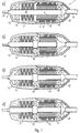
- a motor handpiece 1 is shown, which can be coupled together from two Handpiece parts 12 and 13.
- the handpiece part 12 is the one previously explained Motor arranged, in the example shown in the form of a collectorless DC motor with, for example, made of sheet iron Yoke ring 2, a stator winding 3 and a rotor magnet 4 is formed.
- the Rotor magnet 4 can, for example, be a bipolar, diametrically magnetized Be permanent magnet.
- the Stator winding 3 and the rotor magnet 4 are essentially rotationally symmetrical trained and each have a cylindrical shape.
- the rotor magnet 4 is on a Drive shaft 10 placed non-positively, so that the rotation of the rotor magnet 4th the drive shaft 10 is driven.
- the brushless DC motor is powered by a Supply line 18 supplied with power, the supply line 18 through a Opening at the supply line end of the motor handpiece 1 into the interior of the Handpiece part 12 is guided.
- a ball bearing 14 At the supply line end of the handpiece part 12 there is a ball bearing 14 on which the drive shaft 10 is rotatably mounted.
- the Handpiece part 12 has a removable at its supply line end Cover 22 so that from the supply line end of the motor handpiece 1 the ball bearing 14 is easily accessible and, accordingly, simple to repair can be replaced.
- the second handpiece part 13 comprises the previously mentioned clamping mechanism.
- This clamping mechanism is the one shown in the drawing Embodiments constructed as a quick clamping mechanism analogous to Fig. 5a. I.e. in the exemplary embodiments explained below there is also a Collet 5 is provided, which when the handpiece part 13 is rotated relative to the Handpiece part 12 moved in the longitudinal direction relative to the outer shell of the shaft 10 can be so that a tool 8, e.g. a dental tool that can be found in the Collet 5 is located, simply by turning the serving as a twist grip Handpiece part 13 can be clamped non-positively.
- a tool 8 e.g. a dental tool that can be found in the Collet 5
- FIG. 1 shows a partial cross-sectional view of this clamping mechanism, only one External view of the drive shaft 10 with the portion of the protruding therefrom Collet 5 and the spring 7.
- the spring 7 can, for example, as a plate or spiral coil spring be constructed and - as has already been explained with reference to FIG. 5a - coupled to the collet 5 such that when the collet 5 is pulled into it Handpiece part 13 as a result of a relative rotation of the handpiece part 13 relative to the Handpiece part 12 is compressed.
- the drive shaft 10 is also in the handpiece part 13 the tool-side end rotatably supported by means of a ball bearing 15. All in all is thus a single-shaft system with only two ball bearings 14, 15 for the entire Motor handpiece 1 formed, but still a Tool quick release mechanism (twist grip quick release mechanism) used becomes.
- the collectorless DC motor shown in Fig. 1a (without position indicator) is constructed such that the stator winding 3 is fixed or pluggable to the supply line 18 and the rotor magnet 4 is assigned to the drive shaft 10 in a fixed or screwable manner. This makes it easy to divide and separate the entire engine area into the Supply line 18 and the motor handpiece section possible. Overall, with Optimal minimization of the motor handpiece according to the invention External dimensions and the weight of the motor handpiece achieved. Furthermore, with With the help of the single-shaft system according to the invention, a bearing change on site is simple be performed.
- FIG. 1a Various variants of the motor handpiece shown in FIG. 1a are described below according to the present invention. Here are the corresponding ones Components with identical reference numerals.
- Fig. 1b shows a first variant of the motor handpiece shown in Fig. 1a.
- Analogous to Fig. 1a is again the motor in the handpiece part 12 and the clamping mechanism in Handpiece part 13 housed, with the motor and the clamping mechanism on one and the same wave is put on.
- Ball bearing 14, 15 in the handpiece part 13, which is assigned to the clamping mechanism.
- the two ball bearings 14, 15 at opposite end sections of the Handpiece part 13 arranged, the spring of the clamping mechanism between the two ball bearings 14,15 is housed.
- the drive shaft with that on it attached rotor magnet protrudes cantilevered into the stator winding of the DC motor 1b and is not according to FIG. 1b via a further support bearing in the housing part 12 supported.
- FIG. 1c and 1d show further variants of the first invention Embodiment.
- the motor handpiece according to FIG. 1c corresponds to that in FIG. 1b variant shown, but in addition a third ball bearing 16 on supply line end of the handpiece part 12 is provided.
- the handpiece part 12 in turn has a removable cover, so that the third Ball bearing 16 is easily accessible from the outside.
- the variant shown in Fig. 1d works the motor handpiece shown in Fig. 1a back, each again a ball bearing 14 or 15 in the handpiece part 12 which is assigned to the electric motor, or the Handpiece part 13, which is assigned to the clamping mechanism, is present. While, as in Fig.
- the first ball bearing 14 at the supply line end of Handpiece part 12 is housed, the ball bearing 15 is now on that end of the handpiece 13 which lies opposite the handpiece 12. Also in Fig. 1d, a removable cover 22 is provided so that the ball bearing 14 is simple can be replaced.
- FIG. 2a-2d show different variants of a second embodiment of the present invention.
- This second embodiment corresponds essentially the first embodiment, but in contrast to Fig. 1 the Clamping mechanism or the spring 7 of this clamping mechanism in the supply line-side handpiece part is housed, while the collectorless DC motor is arranged in the tool-side housing part.
- Fig. 2a shows that embodiment, that of the variant shown in Fig. 1d corresponds.
- the handpiece part 13 in which the clamping mechanism or the spring 7 of the Clamping mechanism is housed, has an opening at one end, in which protrudes the supply line 18 which the stator winding 3 of the collectorless DC motor powered if the handpiece part 12 with the handpiece part 13 has been coupled.
- the actuating mechanism of the Clamping system which as a result of twisting the two housing parts 12 and 13th against each other leads to the fact that the sleeve-shaped slotted collet 5 in the Motor handpiece 1 is pushed in and compressed accordingly, is located in the handpiece part 13 together with the spring 7 Clamping mechanism is in turn with the DC motor via one and the same Connected shaft 10, which is formed in one piece or in one piece and only two Bearings 14,15 is rotatably mounted.
- One ball bearing 14 is located on tool-side end of the handpiece part 12, while the other ball bearing 15 that end section of the handpiece part 13 which is the handpiece part 12 is facing.
- Fig. 2b shows a variant of the motor handpiece shown in Fig. 2a according to the present invention, wherein the motor handpiece shown in FIG. 2b corresponds to that in FIG. 1c corresponds to the structure shown, i.e. in addition to the ball bearings 14, 15 it is a third Ball bearings 16 are provided for supporting the drive shaft 10. Because in the 2, the arrangement of the DC motor and the Clamping mechanism compared to the embodiments of Fig. 1 interchanged 2b, the third ball bearing 16 is located on the tool side End of the handpiece part 12. According to FIG. 2b, at the supply line end Handpiece part 13 arranged a ball bearing 15. For this reason, this indicates Handpiece part 13 has a removable cover 22 so that the ball bearing 15 is easy is accessible and replaceable from the supply line side.
- FIG. 2c and 2d show arrangements of the second embodiment of the Motor handpiece according to the invention, which shown in Fig. 1b and 1a Arrangements correspond, but again the arrangement of the DC motor and the clamping mechanism is reversed compared to Fig. 1, i.e. of the Clamping mechanism is located in the handpiece part, which with the Supply line 18 is connected while the DC motor in one Handpiece part is housed, in which the tool 8 is clamped.
- the two ball bearings 14 and 15 are each in the handpiece part 13 arranged at opposite ends thereof, so that the drive shaft cantilevered into the stator winding of the DC motor of the handpiece part 12.
- the two ball bearings 14 and 15 are on the outer ones Ends of the handpiece parts 12 and 13 housed, resulting in the largest possible Vibration rigidity of the drive shaft leads.
- 3a-3e show different variants of a motor handpiece according to a third Embodiment of the present invention.
- FIGS. 3a-3e essentially correspond to those in FIGS Fig. 1a-1d shown variants, wherein according to the third embodiment of the present invention, however, in contrast to FIG. 1, the rotor magnet 4 in one Cavity of the drive shaft 10 is housed.
- 3a shows a first variant of the third exemplary embodiment of the present Invention in the assembled state, i.e. in a state where the two Handpiece parts 12 and 13 are coupled together, for example screwed, while 3b shows the corresponding variant with the handpiece parts 12 and 13 pulled apart represents.
- the drive shaft 10 is self-supporting protrudes the handpiece part 13 and by two ball bearings 14 and 15 in the Handpiece part 13 is held, by assembling the two handpiece parts 12 and 13 that section of the drive shaft 10 in which the rotor magnet 4th is housed, introduced into the stator winding 3 of the collectorless DC motor becomes.
- the stator winding 3 is supplied with current via the supply line 18, as a result of which the rotor magnet 4, which is positively accommodated within the drive shaft 10 set in rotation and at the same time the drive shaft 10 is driven.
- the Clamping mechanism can be analogous to that shown in Fig. 1,2 and 5a Motor handpieces must be constructed.
- the both ball bearings 14 and 15 are arranged analogously to Fig. 1a, i.e. it is each have a ball bearing at the outer end of the handpiece parts 12 and 13.
- the ball bearing 14 arranged at the supply line end can also be housed in the removable cover 22, so that a easy accessibility of the ball bearing 14 is ensured.
- FIG. 3d and 3e show variants of the third exemplary embodiment according to the invention, the arrangement of the ball bearings that shown in Fig. 1d and 1c Ball bearing arrangements corresponds. That is in both Fig. 3d and Fig. 3e supply line side ball bearings 14 and 16 in the removable cover 22 of the Handpiece part 12 housed. While according to the variant shown in Fig. 3d only two ball bearings 14, 15 are used, the drive shaft according to FIG. 3e supported by a total of three ball bearings 14, 15, 16.
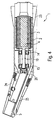
- Fig. 4 shows an example of such a motor handpiece 1 according to the invention with a first housing section 23 and an angled second housing section 24.
- the first housing section 23 houses the motor 2-4, while in the second Housing section 24 any coupling mechanism 5 for receiving a (dental) tool is provided.
- this can Coupling mechanism analogous to the previous embodiments by a Rapid clamping mechanism can be formed, for example by turning the second housing section 24, a tool can be clamped automatically.
- a quick clamping mechanism is at this point on the description of the referenced previous embodiments.
- the motor handpiece 1 shown in FIG. 4 preferably has such separation points, that the two ball bearings 14, 15 are easily accessible when the handpiece is disassembled to exchange them.
- the motor handpiece 1 for dental purposes also a channel 25 to a treatment site e.g. Light, Supply spray air or spray water.
Landscapes
- Health & Medical Sciences (AREA)
- Oral & Maxillofacial Surgery (AREA)
- Dentistry (AREA)
- Epidemiology (AREA)
- Life Sciences & Earth Sciences (AREA)
- Animal Behavior & Ethology (AREA)
- General Health & Medical Sciences (AREA)
- Public Health (AREA)
- Veterinary Medicine (AREA)
- Dental Tools And Instruments Or Auxiliary Dental Instruments (AREA)
- Power Steering Mechanism (AREA)
- Control And Other Processes For Unpacking Of Materials (AREA)
- Toilet Supplies (AREA)
Applications Claiming Priority (2)
| Application Number | Priority Date | Filing Date | Title |
|---|---|---|---|
| DE19753491A DE19753491A1 (de) | 1997-12-02 | 1997-12-02 | Motorhandstück |
| DE19753491 | 1997-12-02 |
Publications (4)
| Publication Number | Publication Date |
|---|---|
| EP0920839A2 true EP0920839A2 (fr) | 1999-06-09 |
| EP0920839A3 EP0920839A3 (fr) | 2000-12-13 |
| EP0920839B1 EP0920839B1 (fr) | 2006-04-26 |
| EP0920839B2 EP0920839B2 (fr) | 2012-12-19 |
Family
ID=7850525
Family Applications (1)
| Application Number | Title | Priority Date | Filing Date |
|---|---|---|---|
| EP98122300A Expired - Lifetime EP0920839B2 (fr) | 1997-12-02 | 1998-11-24 | Pièce à main à moteur |
Country Status (5)
| Country | Link |
|---|---|
| US (1) | US6126442A (fr) |
| EP (1) | EP0920839B2 (fr) |
| JP (1) | JP3448229B2 (fr) |
| AT (1) | ATE324078T1 (fr) |
| DE (2) | DE19753491A1 (fr) |
Cited By (2)
| Publication number | Priority date | Publication date | Assignee | Title |
|---|---|---|---|---|
| EP1362559A1 (fr) | 2002-04-24 | 2003-11-19 | W & H Dentalwerk Bürmoos GmbH | Pièce à main à moteur |
| WO2020157125A1 (fr) * | 2019-01-29 | 2020-08-06 | NWT Management GmbH | Poignée pour un appareil de traitement médical ou cosmétique |
Families Citing this family (12)
| Publication number | Priority date | Publication date | Assignee | Title |
|---|---|---|---|---|
| DE10161945A1 (de) * | 2001-12-17 | 2003-07-17 | W & H Dentalwerk Buermoos Ges | Bürstenloser Elektro-Motor sowie Instrument für eine medizinische Vorrichtung mit einem solchen Motor |
| EP1675523B1 (fr) * | 2004-02-17 | 2008-05-28 | Bien-Air Holding SA | Piece a main a usage dentaire ou chirurgical avec mecanisme de serrage |
| US20050181326A1 (en) * | 2004-02-17 | 2005-08-18 | Bien-Air Holding S.A. | Powered handpiece for dental or surgical use |
| DE102006051510A1 (de) * | 2006-03-09 | 2007-09-13 | Kaltenbach & Voigt Gmbh | Zahnärztliches, zahnmedizinisches oder dentaltechnisches Handstück mit Elektromotor |
| DE102006013455B3 (de) * | 2006-03-23 | 2007-07-12 | Gebr. Brasseler Gmbh & Co. Kg | Dentalinstrumentenhandhabungsvorrichtung |
| JP4912752B2 (ja) * | 2006-05-30 | 2012-04-11 | 日本電産テクノモータホールディングス株式会社 | モータ |
| DE102007014691A1 (de) * | 2007-03-27 | 2008-10-02 | Kaltenbach & Voigt Gmbh | Elektromotor zur Verwendung in einem zahnärztlichen, zahnmedizinischen oder dentaltechnischen Handstück sowie Stator hierfür |
| KR101059742B1 (ko) | 2009-12-31 | 2011-09-01 | (주)마이크로엔엑스 | 핸드 피스용 모터 |
| FR3016283B1 (fr) * | 2014-01-13 | 2016-01-15 | Guy Charles Levy | Entrainement pour contre angle en dentisterie |
| KR101663983B1 (ko) * | 2014-12-30 | 2016-10-11 | 이종건 | 발광수단을 갖는 슬림화된 핸드피스 |
| KR101653543B1 (ko) * | 2014-12-30 | 2016-09-02 | 이종건 | 고속회전이 가능한 저진동 구조를 갖는 핸드피스 |
| US10149727B2 (en) * | 2016-12-09 | 2018-12-11 | Ethicon Llc | Surgical tool and robotic surgical system interfaces |
Citations (1)
| Publication number | Priority date | Publication date | Assignee | Title |
|---|---|---|---|---|
| DE4406855A1 (de) | 1994-03-02 | 1995-09-07 | Kaltenbach & Voigt | Gerades Motorhandstück, insbesondere für medizinische Zwecke, vorzugsweise für ein medizinisches oder dentales Labor |
Family Cites Families (16)
| Publication number | Priority date | Publication date | Assignee | Title |
|---|---|---|---|---|
| US2660441A (en) * | 1951-07-12 | 1953-11-24 | Magnus E Toelcke | Collet chuck |
| US3109238A (en) † | 1961-11-28 | 1963-11-05 | Samuel B Marks | Portable dental drill |
| AT296494B (de) † | 1968-07-24 | 1972-02-10 | Kaltenbach & Voigt | Zahnärztliches Instrument, insbesondere Hand- oder Winkelstück |
| JPS4860398U (fr) † | 1971-11-09 | 1973-08-01 | ||
| US3928701A (en) † | 1974-07-16 | 1975-12-23 | Soll Roehner | Helix of a series of discarded vehicle tires |
| US3978586A (en) * | 1975-02-10 | 1976-09-07 | The Denticator Company, Inc. | Dental apparatus |
| CH618335A5 (fr) † | 1977-05-31 | 1980-07-31 | Arnegger Richard E | |
| US4183140A (en) * | 1977-05-31 | 1980-01-15 | Concept Inc. | Dental stain remover |
| US4184256A (en) * | 1977-12-12 | 1980-01-22 | Kaltenbach & Voigt Gmbh & Co. | Miniature motor having an internal coolant line |
| GB2039095B (en) † | 1978-12-07 | 1982-11-24 | Hansen J S | Electric motors speed regulation |
| DE2855874A1 (de) † | 1978-12-22 | 1980-07-10 | Siemens Ag | Zahnaerztliche handstueckanordnung |
| JPS5656314U (fr) * | 1979-10-08 | 1981-05-15 | ||
| JPS61139208A (ja) † | 1984-12-06 | 1986-06-26 | 東芝プラント建設株式会社 | ケ−ブル延線用のケ−ブル収納装置 |
| DD231490A1 (de) † | 1984-12-20 | 1986-01-02 | Berlin Med Geraete | Elektrisches antriebssystem fuer ein zahnaerztliches handstueck |
| JPH0737606Y2 (ja) * | 1993-08-20 | 1995-08-30 | 株式会社中西歯科器械製作所 | 歯科用ハンドピース |
| DE19644491A1 (de) † | 1996-10-25 | 1998-04-30 | Kaltenbach & Voigt | Dentales Handstück |
-
1997
- 1997-12-02 DE DE19753491A patent/DE19753491A1/de not_active Withdrawn
-
1998
- 1998-11-23 US US09/197,710 patent/US6126442A/en not_active Expired - Lifetime
- 1998-11-24 EP EP98122300A patent/EP0920839B2/fr not_active Expired - Lifetime
- 1998-11-24 AT AT98122300T patent/ATE324078T1/de active
- 1998-11-24 DE DE59813513T patent/DE59813513D1/de not_active Expired - Lifetime
- 1998-11-30 JP JP33991498A patent/JP3448229B2/ja not_active Expired - Lifetime
Patent Citations (1)
| Publication number | Priority date | Publication date | Assignee | Title |
|---|---|---|---|---|
| DE4406855A1 (de) | 1994-03-02 | 1995-09-07 | Kaltenbach & Voigt | Gerades Motorhandstück, insbesondere für medizinische Zwecke, vorzugsweise für ein medizinisches oder dentales Labor |
Cited By (5)
| Publication number | Priority date | Publication date | Assignee | Title |
|---|---|---|---|---|
| EP1362559A1 (fr) | 2002-04-24 | 2003-11-19 | W & H Dentalwerk Bürmoos GmbH | Pièce à main à moteur |
| WO2020157125A1 (fr) * | 2019-01-29 | 2020-08-06 | NWT Management GmbH | Poignée pour un appareil de traitement médical ou cosmétique |
| CN113365529A (zh) * | 2019-01-29 | 2021-09-07 | Nwt管理有限责任公司 | 用于医疗或美容加工器具的手持件 |
| CN113365529B (zh) * | 2019-01-29 | 2024-08-02 | Nwt管理有限责任公司 | 用于医疗或美容加工器具的手持件 |
| US12082675B2 (en) | 2019-01-29 | 2024-09-10 | NWT Management GmbH | Handpiece for a medical or cosmetic processing device |
Also Published As
| Publication number | Publication date |
|---|---|
| EP0920839B2 (fr) | 2012-12-19 |
| EP0920839A3 (fr) | 2000-12-13 |
| DE19753491A1 (de) | 1999-06-10 |
| JPH11221232A (ja) | 1999-08-17 |
| ATE324078T1 (de) | 2006-05-15 |
| DE59813513D1 (de) | 2006-06-01 |
| US6126442A (en) | 2000-10-03 |
| EP0920839B1 (fr) | 2006-04-26 |
| JP3448229B2 (ja) | 2003-09-22 |
Similar Documents
| Publication | Publication Date | Title |
|---|---|---|
| EP1993463B1 (fr) | Pièce à main de dentisterie comportant un moteur électrique | |
| EP0920839B1 (fr) | Pièce à main à moteur | |
| DE68918335T2 (de) | Antrieb für ein Bohr- und/oder Schlagwerkzeug. | |
| DE2855719C2 (fr) | ||
| DE2834099C2 (de) | Permanentmagnetisch erregter Gleichstrom-Kleinstmotor zum Antrieb eines ankuppelbaren zahnärztlichen Handinstrumentes | |
| EP0888091B1 (fr) | Piece a main dentaire | |
| EP0491894B1 (fr) | Entrainement de la broche principale d'une machine-outil | |
| DE102004020177A1 (de) | Handwerkzeugmaschine mit einem drehenden und/oder schlagenden Antrieb | |
| WO2023117586A1 (fr) | Machine électrique dotée d'un dispositif de couplage à plusieurs parties | |
| DE19833794A1 (de) | Handgeführtes Elektrowerkzeug, insbesondere Stichsäge | |
| EP1199500B1 (fr) | Barillet de commande des passages de vitesses dans une transmission | |
| EP1923173A1 (fr) | Machine-outil manuelle | |
| EP1048401A2 (fr) | Dispositif de changement d'outils | |
| DE102005025352B4 (de) | Außenwirbelvorrichtung mit einem Wirbelaggregat | |
| DE9001702U1 (de) | Elektrowerkzeug | |
| DE102004049630A1 (de) | Druckwasserreinigungsgerät | |
| DE19604628A1 (de) | Gleichstrommotor zum Antrieb eines dentalen Instrumentes | |
| WO2009049807A1 (fr) | Moteur électrique à utiliser dans un outil à main en médecine dentaire, chirurgie dentaire ou technique dentaire | |
| EP1362559B1 (fr) | Pièce à main à moteur | |
| DE4322981A1 (de) | Stellantrieb für die Luftklappe einer Heizungs- oder Klimaanlage für Kraftfahrzeuge | |
| DE102024125666B3 (de) | Traktionsmaschine und Fahrzeug | |
| EP1600665A1 (fr) | Mécanisme de réglage à moteur électrique | |
| EP4696188A1 (fr) | Appareil manuel pour l'abrasion des callosités | |
| DE3527796A1 (de) | Elektrisches antriebssystem fuer ein zahnaerztliches handstueck | |
| DE10003512A1 (de) | Vorrichtung zur Unterstützung der Selbsthemmung bei Elektromotoren |
Legal Events
| Date | Code | Title | Description |
|---|---|---|---|
| PUAI | Public reference made under article 153(3) epc to a published international application that has entered the european phase |
Free format text: ORIGINAL CODE: 0009012 |
|
| AK | Designated contracting states |
Kind code of ref document: A2 Designated state(s): AT CH DE FR IT LI |
|
| AX | Request for extension of the european patent |
Free format text: AL;LT;LV;MK;RO;SI |
|
| PUAL | Search report despatched |
Free format text: ORIGINAL CODE: 0009013 |
|
| AK | Designated contracting states |
Kind code of ref document: A3 Designated state(s): AT BE CH CY DE DK ES FI FR GB GR IE IT LI LU MC NL PT SE |
|
| AX | Request for extension of the european patent |
Free format text: AL;LT;LV;MK;RO;SI |
|
| RIC1 | Information provided on ipc code assigned before grant |
Free format text: 7A 61C 1/08 A, 7A 61C 1/06 B, 7A 61C 1/18 B |
|
| 17P | Request for examination filed |
Effective date: 20010411 |
|
| AKX | Designation fees paid |
Free format text: AT CH DE FR IT LI |
|
| RAP1 | Party data changed (applicant data changed or rights of an application transferred) |
Owner name: KALTENBACH & VOIGT GMBH & CO. KG |
|
| 17Q | First examination report despatched |
Effective date: 20040812 |
|
| GRAP | Despatch of communication of intention to grant a patent |
Free format text: ORIGINAL CODE: EPIDOSNIGR1 |
|
| GRAS | Grant fee paid |
Free format text: ORIGINAL CODE: EPIDOSNIGR3 |
|
| GRAA | (expected) grant |
Free format text: ORIGINAL CODE: 0009210 |
|
| AK | Designated contracting states |
Kind code of ref document: B1 Designated state(s): AT CH DE FR IT LI |
|
| PG25 | Lapsed in a contracting state [announced via postgrant information from national office to epo] |
Ref country code: IT Free format text: LAPSE BECAUSE OF FAILURE TO SUBMIT A TRANSLATION OF THE DESCRIPTION OR TO PAY THE FEE WITHIN THE PRESCRIBED TIME-LIMIT;WARNING: LAPSES OF ITALIAN PATENTS WITH EFFECTIVE DATE BEFORE 2007 MAY HAVE OCCURRED AT ANY TIME BEFORE 2007. THE CORRECT EFFECTIVE DATE MAY BE DIFFERENT FROM THE ONE RECORDED. Effective date: 20060426 |
|
| RAP1 | Party data changed (applicant data changed or rights of an application transferred) |
Owner name: KALTENBACH & VOIGT GMBH |
|
| REF | Corresponds to: |
Ref document number: 59813513 Country of ref document: DE Date of ref document: 20060601 Kind code of ref document: P |
|
| REG | Reference to a national code |
Ref country code: CH Ref legal event code: NV Representative=s name: A. BRAUN, BRAUN, HERITIER, ESCHMANN AG PATENTANWAE |
|
| ET | Fr: translation filed | ||
| PLAX | Notice of opposition and request to file observation + time limit sent |
Free format text: ORIGINAL CODE: EPIDOSNOBS2 |
|
| PLBI | Opposition filed |
Free format text: ORIGINAL CODE: 0009260 |
|
| 26 | Opposition filed |
Opponent name: W&H DENTALWERK BUERMOOS GMBH Effective date: 20070126 |
|
| PLAF | Information modified related to communication of a notice of opposition and request to file observations + time limit |
Free format text: ORIGINAL CODE: EPIDOSCOBS2 |
|
| PLBB | Reply of patent proprietor to notice(s) of opposition received |
Free format text: ORIGINAL CODE: EPIDOSNOBS3 |
|
| REG | Reference to a national code |
Ref country code: CH Ref legal event code: PFA Owner name: KALTENBACH & VOIGT GMBH Free format text: KALTENBACH & VOIGT GMBH#BISMARCKRING 39#88400 BIBERACH / RISS (DE) -TRANSFER TO- KALTENBACH & VOIGT GMBH#BISMARCKRING 39#88400 BIBERACH / RISS (DE) |
|
| PLAY | Examination report in opposition despatched + time limit |
Free format text: ORIGINAL CODE: EPIDOSNORE2 |
|
| PLAB | Opposition data, opponent's data or that of the opponent's representative modified |
Free format text: ORIGINAL CODE: 0009299OPPO |
|
| PLBC | Reply to examination report in opposition received |
Free format text: ORIGINAL CODE: EPIDOSNORE3 |
|
| APBM | Appeal reference recorded |
Free format text: ORIGINAL CODE: EPIDOSNREFNO |
|
| APBP | Date of receipt of notice of appeal recorded |
Free format text: ORIGINAL CODE: EPIDOSNNOA2O |
|
| APAH | Appeal reference modified |
Free format text: ORIGINAL CODE: EPIDOSCREFNO |
|
| APBQ | Date of receipt of statement of grounds of appeal recorded |
Free format text: ORIGINAL CODE: EPIDOSNNOA3O |
|
| APAH | Appeal reference modified |
Free format text: ORIGINAL CODE: EPIDOSCREFNO |
|
| APBU | Appeal procedure closed |
Free format text: ORIGINAL CODE: EPIDOSNNOA9O |
|
| PUAH | Patent maintained in amended form |
Free format text: ORIGINAL CODE: 0009272 |
|
| STAA | Information on the status of an ep patent application or granted ep patent |
Free format text: STATUS: PATENT MAINTAINED AS AMENDED |
|
| 27A | Patent maintained in amended form |
Effective date: 20121219 |
|
| AK | Designated contracting states |
Kind code of ref document: B2 Designated state(s): AT CH DE FR IT LI |
|
| REG | Reference to a national code |
Ref country code: CH Ref legal event code: AELC |
|
| REG | Reference to a national code |
Ref country code: DE Ref legal event code: R102 Ref document number: 59813513 Country of ref document: DE Effective date: 20121219 |
|
| REG | Reference to a national code |
Ref country code: CH Ref legal event code: PCAR Free format text: NEW ADDRESS: HOLBEINSTRASSE 36-38, 4051 BASEL (CH) |
|
| REG | Reference to a national code |
Ref country code: FR Ref legal event code: PLFP Year of fee payment: 18 |
|
| REG | Reference to a national code |
Ref country code: FR Ref legal event code: PLFP Year of fee payment: 19 |
|
| REG | Reference to a national code |
Ref country code: FR Ref legal event code: PLFP Year of fee payment: 20 |
|
| PGFP | Annual fee paid to national office [announced via postgrant information from national office to epo] |
Ref country code: FR Payment date: 20171124 Year of fee payment: 20 Ref country code: DE Payment date: 20171207 Year of fee payment: 20 |
|
| PGFP | Annual fee paid to national office [announced via postgrant information from national office to epo] |
Ref country code: AT Payment date: 20171122 Year of fee payment: 20 Ref country code: CH Payment date: 20171123 Year of fee payment: 20 Ref country code: IT Payment date: 20171130 Year of fee payment: 20 |
|
| REG | Reference to a national code |
Ref country code: DE Ref legal event code: R071 Ref document number: 59813513 Country of ref document: DE |
|
| REG | Reference to a national code |
Ref country code: CH Ref legal event code: PL |
|
| REG | Reference to a national code |
Ref country code: AT Ref legal event code: MK07 Ref document number: 324078 Country of ref document: AT Kind code of ref document: T Effective date: 20181124 |