EP0920885A1 - Système de traitement cardiaque pour la détection et le traitement de défaillances cardiaques - Google Patents
Système de traitement cardiaque pour la détection et le traitement de défaillances cardiaques Download PDFInfo
- Publication number
- EP0920885A1 EP0920885A1 EP98122974A EP98122974A EP0920885A1 EP 0920885 A1 EP0920885 A1 EP 0920885A1 EP 98122974 A EP98122974 A EP 98122974A EP 98122974 A EP98122974 A EP 98122974A EP 0920885 A1 EP0920885 A1 EP 0920885A1
- Authority
- EP
- European Patent Office
- Prior art keywords
- patient
- heart
- rate
- lvd
- pacing
- Prior art date
- Legal status (The legal status is an assumption and is not a legal conclusion. Google has not performed a legal analysis and makes no representation as to the accuracy of the status listed.)
- Granted
Links
- 230000000747 cardiac effect Effects 0.000 title claims abstract description 42
- 206010019280 Heart failures Diseases 0.000 title claims abstract description 25
- 238000011282 treatment Methods 0.000 title claims description 10
- 206010049694 Left Ventricular Dysfunction Diseases 0.000 claims abstract description 84
- 230000004044 response Effects 0.000 claims abstract description 29
- 238000005314 correlation function Methods 0.000 claims description 17
- 239000003814 drug Substances 0.000 claims description 11
- 229940079593 drug Drugs 0.000 claims description 11
- 238000000034 method Methods 0.000 claims description 11
- 210000005240 left ventricle Anatomy 0.000 claims description 9
- 238000012545 processing Methods 0.000 claims description 9
- 210000005241 right ventricle Anatomy 0.000 claims description 8
- 230000008569 process Effects 0.000 claims description 6
- 238000012544 monitoring process Methods 0.000 claims description 5
- 238000001514 detection method Methods 0.000 abstract description 4
- 208000014526 Conduction disease Diseases 0.000 abstract description 2
- 238000002651 drug therapy Methods 0.000 abstract 1
- 230000006870 function Effects 0.000 description 18
- 238000010586 diagram Methods 0.000 description 14
- 230000008859 change Effects 0.000 description 10
- 230000002861 ventricular Effects 0.000 description 10
- 230000009977 dual effect Effects 0.000 description 9
- 230000002269 spontaneous effect Effects 0.000 description 6
- 210000005246 left atrium Anatomy 0.000 description 5
- 238000005316 response function Methods 0.000 description 5
- 230000000694 effects Effects 0.000 description 4
- 230000000977 initiatory effect Effects 0.000 description 4
- 206010006580 Bundle branch block left Diseases 0.000 description 3
- 210000005242 cardiac chamber Anatomy 0.000 description 3
- 150000003943 catecholamines Chemical class 0.000 description 3
- 238000004891 communication Methods 0.000 description 3
- 230000008602 contraction Effects 0.000 description 3
- 238000003745 diagnosis Methods 0.000 description 3
- 230000001965 increasing effect Effects 0.000 description 3
- 238000002156 mixing Methods 0.000 description 3
- 210000005245 right atrium Anatomy 0.000 description 3
- 206010006578 Bundle-Branch Block Diseases 0.000 description 2
- 206010007559 Cardiac failure congestive Diseases 0.000 description 2
- 230000002159 abnormal effect Effects 0.000 description 2
- 230000003466 anti-cipated effect Effects 0.000 description 2
- 230000009118 appropriate response Effects 0.000 description 2
- 210000003748 coronary sinus Anatomy 0.000 description 2
- 201000010099 disease Diseases 0.000 description 2
- 208000037265 diseases, disorders, signs and symptoms Diseases 0.000 description 2
- 230000000763 evoking effect Effects 0.000 description 2
- 201000001715 left bundle branch hemiblock Diseases 0.000 description 2
- 230000006461 physiological response Effects 0.000 description 2
- 230000024977 response to activity Effects 0.000 description 2
- 238000004904 shortening Methods 0.000 description 2
- 208000020597 Cardiac conduction disease Diseases 0.000 description 1
- 206010056370 Congestive cardiomyopathy Diseases 0.000 description 1
- 201000010046 Dilated cardiomyopathy Diseases 0.000 description 1
- 241001385887 Tachys Species 0.000 description 1
- 230000004913 activation Effects 0.000 description 1
- 230000005540 biological transmission Effects 0.000 description 1
- 230000036770 blood supply Effects 0.000 description 1
- 238000004364 calculation method Methods 0.000 description 1
- 239000002131 composite material Substances 0.000 description 1
- 238000013480 data collection Methods 0.000 description 1
- 230000003247 decreasing effect Effects 0.000 description 1
- 230000003412 degenerative effect Effects 0.000 description 1
- 230000002939 deleterious effect Effects 0.000 description 1
- 230000006866 deterioration Effects 0.000 description 1
- 238000011161 development Methods 0.000 description 1
- 238000012377 drug delivery Methods 0.000 description 1
- 208000012727 heart conduction disease Diseases 0.000 description 1
- 230000005986 heart dysfunction Effects 0.000 description 1
- 230000004217 heart function Effects 0.000 description 1
- 230000000004 hemodynamic effect Effects 0.000 description 1
- 239000007943 implant Substances 0.000 description 1
- 238000010348 incorporation Methods 0.000 description 1
- 230000001939 inductive effect Effects 0.000 description 1
- 238000004137 mechanical activation Methods 0.000 description 1
- 230000028161 membrane depolarization Effects 0.000 description 1
- 230000000877 morphologic effect Effects 0.000 description 1
- 238000011369 optimal treatment Methods 0.000 description 1
- 230000000750 progressive effect Effects 0.000 description 1
- 230000009467 reduction Effects 0.000 description 1
- 230000001360 synchronised effect Effects 0.000 description 1
- 238000002560 therapeutic procedure Methods 0.000 description 1
- 210000003462 vein Anatomy 0.000 description 1
- 230000002618 waking effect Effects 0.000 description 1
Images


Classifications
-
- A—HUMAN NECESSITIES
- A61—MEDICAL OR VETERINARY SCIENCE; HYGIENE
- A61N—ELECTROTHERAPY; MAGNETOTHERAPY; RADIATION THERAPY; ULTRASOUND THERAPY
- A61N1/00—Electrotherapy; Circuits therefor
- A61N1/18—Applying electric currents by contact electrodes
- A61N1/32—Applying electric currents by contact electrodes alternating or intermittent currents
- A61N1/36—Applying electric currents by contact electrodes alternating or intermittent currents for stimulation
- A61N1/362—Heart stimulators
- A61N1/365—Heart stimulators controlled by a physiological parameter, e.g. heart potential
- A61N1/36514—Heart stimulators controlled by a physiological parameter, e.g. heart potential controlled by a physiological quantity other than heart potential, e.g. blood pressure
-
- A—HUMAN NECESSITIES
- A61—MEDICAL OR VETERINARY SCIENCE; HYGIENE
- A61N—ELECTROTHERAPY; MAGNETOTHERAPY; RADIATION THERAPY; ULTRASOUND THERAPY
- A61N1/00—Electrotherapy; Circuits therefor
- A61N1/18—Applying electric currents by contact electrodes
- A61N1/32—Applying electric currents by contact electrodes alternating or intermittent currents
- A61N1/36—Applying electric currents by contact electrodes alternating or intermittent currents for stimulation
- A61N1/362—Heart stimulators
- A61N1/365—Heart stimulators controlled by a physiological parameter, e.g. heart potential
- A61N1/36585—Heart stimulators controlled by a physiological parameter, e.g. heart potential controlled by two or more physical parameters
-
- A—HUMAN NECESSITIES
- A61—MEDICAL OR VETERINARY SCIENCE; HYGIENE
- A61N—ELECTROTHERAPY; MAGNETOTHERAPY; RADIATION THERAPY; ULTRASOUND THERAPY
- A61N1/00—Electrotherapy; Circuits therefor
- A61N1/18—Applying electric currents by contact electrodes
- A61N1/32—Applying electric currents by contact electrodes alternating or intermittent currents
- A61N1/36—Applying electric currents by contact electrodes alternating or intermittent currents for stimulation
- A61N1/362—Heart stimulators
- A61N1/37—Monitoring; Protecting
- A61N1/3702—Physiological parameters
-
- A—HUMAN NECESSITIES
- A61—MEDICAL OR VETERINARY SCIENCE; HYGIENE
- A61N—ELECTROTHERAPY; MAGNETOTHERAPY; RADIATION THERAPY; ULTRASOUND THERAPY
- A61N1/00—Electrotherapy; Circuits therefor
- A61N1/18—Applying electric currents by contact electrodes
- A61N1/32—Applying electric currents by contact electrodes alternating or intermittent currents
- A61N1/36—Applying electric currents by contact electrodes alternating or intermittent currents for stimulation
- A61N1/362—Heart stimulators
- A61N1/3627—Heart stimulators for treating a mechanical deficiency of the heart, e.g. congestive heart failure or cardiomyopathy
Definitions
- This invention relates to cardiac pacemakers ad cardiac diagnostic devices and, more particularly, such implantable devices having the capability of automatically determining the onset or progression of heart failure, e.g., left ventricular dysfunction, and for delivering a appropriate therapy.
- LVD left ventricular dysfunction
- CHF congestive heart failure
- LVD left ventricular dysfunction
- CHF congestive heart failure
- the ejection fraction from the left ventricle is reduced, and the ability of the stroke volume to respond to exercise is limited.
- LVD may proceed in different ways, the result is a degenerative reduction in cardiac output.
- LVD may be produced by a degree of left bundle branch block, leading to loss of synchrony between the left atrium and the left ventricle.
- cardiac output is reduced, and the heart responds so as to increase cardiac output toward a normal level primarily by heart rate increase.
- the rate increase may be manifested in several different ways, e.g., there may be an increase in the daily lower spontaneous rate, i.e., the nighttime rate when the patient is at rest.
- the changed conductive patterns which may form the basis of the LVD can lead to changes in the cardiac signal, e.g., an increased width of the depolarization signal, or QRS.
- QRS depolarization signal
- patients with LVD are also known to have elevated levels of catecholamines at rest, which induces a higher heart rate at rest.
- the QT interval for such a patient is affected by the catecholamine level, and thus has a changed pattern during exercise as well.
- QT interval is influenced independently by heart rate alone, as well as by exercise and catecholemines, it is not known to what extent each of these factors or both are responsible for the changed QT response to exercise in LVD patients. However, it is known that patients with LVD clearly have a different pattern of QT interval shortening during exercise.
- the basis for this invention is obtaining information from cardiac signals for deriving an indication of LVD, or onset of LVD. It is seen that for a implanted device such as a cardiac pacemaker, which can sense cardiac signals ad process heart rate (or R-R interval), QT interval, and QRS length, as well as QRS and P-wave morphology, information can be obtained for tracking changes in left ventricular function, and in particular for indicating progression toward some degree, or form of left ventricular dysfunction.
- a cardiac pacemaker which can sense cardiac signals ad process heart rate (or R-R interval), QT interval, and QRS length, as well as QRS and P-wave morphology
- a rate responsive pacemaker which uses QT interval as the rate indicating parameter, such as pacemakers made by Vitatron Medical, the assignee of this invention, can be adapted to provide information relating to left ventricular hemodynamic performance, and for indicating the onset of LVD.
- a QT rate responsive pacemaker there is provided a algorithm for automatically adjusting the rate responsive parameters, i.e., the correlation function between QT and desired rate. This adjustment is suitably done on a daily basis where the pacemaker measures a slope of the correlation function at the lower rate limit, and adjusts the QT-rate function between lower rate limit (LRL) and upper rate limit (URL) accordingly.
- LDL lower rate limit
- URL upper rate limit
- LVD is generally symptomatic of cardiac conduction disorders
- other variations in sensed cardiac signals may also be used for making an indication of LVD, or for corroborating progression toward LVD.
- the evoked T-wave amplitude may not increase in a normal manner during exercise.
- the evoked T-wave amplitude increases up to about fifty percent during exercise, an increase which may correlate with stroke volume.
- a change in the variation of T-wave amplitude with respect to exercise, and consequent heart rate can be easily measured and tracked in a QT rate responsive pacemaker, or any pacemaker adapted to sense and recover the T-waves.
- changes in QRS duration (width) and/or morphology may also be detected and tracked for detection of a trend.
- a pacemaker or other implanted device having the capacity to identify the onset of cardiac heart failure, and in particular LVD, and to provide such indication to the patient and the patient's physician, or to provide for an appropriate automatic response to treat the changing patient condition.
- LVD left heart conduction disorders
- LBBB left heart conduction disorders
- the system is an implantable cardiac pacing system having a pacemaker and a lead for delivering pacing pulses to and receiving cardiac signals from at least the patient's right ventricle.
- the pacemaker system may also include a lead for delivery of pacing stimuli to the left ventricle and/or the left atrium in response to an indication of heart failure such as LVD, or a drug dispensing system for dispensing an appropriate drug for treating the heart failure.
- the pacemaker is preferably a rate responsive pacemaker, having one or more sensors for sensing a parameter indicative of pacing rate, and for pacing the patient on demand between a lower rate limit and an upper rate limit.
- the pacemaker determines QT interval, and stores data representative of changes in QT interval as a function of heart rate paced and/or spontaneous as well as the patient's spontaneous lower rate when at rest. Variations in the correlation of QT interval and heart rate, and/or variations in patient lower rate at rest are processed to provide a time trend, or profile, from which a determination is made as to whether or not LVD is indicated.
- other data derived from cardiac signals is processed and stored, e.g., QRS width, T-wave amplitude, etc. Trends in this data are periodically evaluated, e.g., on a daily basis, and stored for downloading to an external programmer or for automatic initiation of a treatment response.
- the implanted system may be solely dedicated to detection and storage of cardiac data, and processing of such data to provide an indication of LVD when interrogated.
- the invention is carried out by a system such as a rate responsive pacemaker system which can pace and sense in any combination or all of the four cardiac chambers.
- the treatment response upon an indication of onset of LVD has a number of embodiments, including changing the rate response function; changing sensor blending for dual or plural sensor rate responsive pacemakers; initiating three or four chamber pacing to achieve improved left heart response, e.g., synchronous ventricular pacing and/or other multi-chamber sequential pacing; and providing for a measured release of an appropriate drug for treating the LVD.
- the pacemaker device may be implanted with software for carrying out normal dual chamber pacing, but may be upgraded by programmer downloading to provide different pacing functions, or to function as a three or four chamber pacemaker, along with utilization of an additional lead or leads for delivering stimulus pulses to the left heart chambers.
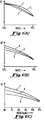
- each of the curves shown is a separate rate-responsive function, or correlation function for determining rate as a function of sensed QT.
- Curve 1 is the least aggressive of the curves, in the sense of providing a change in rate for a given change in QT.
- curve 2 is somewhat more aggressive, and the third curve is the most aggressive of the three.
- LNL lower rate limit
- URL upper rate limit
- Curve 4 is presented as a curve for a normal patient, with a first value of QT at LRL (e.g., 70 bpm). After some time and deterioration of normal cardiac function, the curve may change to that shown at 5, corresponding to a smaller QT at LRL. Such a smaller or reduced QT would correspond to the increased catecholamine level, as mentioned, above.
- Curve 6 represents a condition more advanced toward LVD, showing an even smaller QT at LRL.
- FIG. 1(C) there is shown another set of curves that represents changes in a patient's QT-rate relationship, as the patient progresses toward LVD.
- Curve 7 is a starting condition which corresponds approximately to curve 4 as seen in Figure 1B.
- curve 8 After some time, it is determined that the patient's QT-rate relationship is as represented by curve 8.
- the patient's spontaneous rate does not in fact drop below about 70 bpm, and a different characteristic is exhibited for the relationship between QT and rates of about 70 and an upper limit of about 110 bpm.
- the patient condition is as represented in curve 9, where the patient's lowest spontaneous rate, at nighttime or other rest, is about 80 bpm.
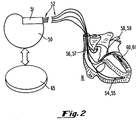
- a pacemaker or other implantable device such as a combined pacemaker-cardioverter defibrillator 50, is a standard available pacemaker for generating pacing pulses and for sensing cardiac signals.
- a connector block 51 receives the proximal end of four leads, designated at 52, which go to respective locations in the four respective chambers of the heart. It is understood that the invention may normally be practiced with only a dual chamber pacemaker, or even a single chamber (VVI) pacemaker.
- a 3- or 4-chamber pacemaker at the time of implant it may be desired to operate the pacemaker only as a dual chamber pacemaker with lead connections to the right atrium and right ventricle, the pacemaker being adapted to be connected with additional leads for pacing and sensing in the left ventricle and left atrium when and as LVD is determined.
- a first of the leads is positioned so that its distal tip is in the right ventricle, and carries bipolar electrodes 54, 55.
- the lead arrangement may be unipolar, using only a far distal tip lead, in combination with the electrode case as the indifferent lead.
- a second lead is positioned so that its distal end is in the right atrium, carrying electrodes 56, 57.
- Another lead is positioned via the coronary sinus for pacing and sensing in the left atrium, having electrodes 58, 59 positioned at about its distal end.
- a fourth lead is illustrated positioned to pace and sense in the left ventricle, via the coronary sinus and the great vein, having electrodes 60, 61.
- a four-chamber system is illustrated so as to indicate the scope of the invention.
- a drug delivery system shown at 65, is in communication with pacemaker 50, and can be automatically activated to release an appropriate drug for treatment of LVD whenever LVD is detected.
- the link between the device 50 and the drug dispensing unit 65 may be either by direct wire connection or may be by telemetry.
- FIG. 3 is a functional block diagram of an implantable pacemaker of the type in which the present invention may be practiced.
- the disclosed embodiment takes the form of a microprocessor controlled device.
- the invention might usefully be practiced in other types of devices, including those employing dedicated digital circuitry, and perhaps even in devices comprised primarily of analog timing and control circuitry.
- Figure 3 should be considered exemplary, rather than limiting with regard to the scope of applications of the present invention.
- the invention is disclosed as embodied in a pacemaker, it is equally applicable to incorporation in a cardioverter, or combined cardioverter pacemaker, or even cardioverter defibrillator pacemaker. While the following discussion of Figure 3 assumes a single chamber ventricular pacing system, it is to be understood that the invention is applicable to 2-,3- or 4-chamber systems.
- the primary elements of the apparatus illustrated in Figure 3 are microprocessor 100, read only memory 102, random access memory 104, a digital controller 106, input and output amplifiers 110 and 108 respectively, and a telemetry/programming unit 120.
- Read only memory 102 stores the basic programming for the device, including the primary instructions set defining the computations performed to derive the various timing intervals performed by the device.
- Random access memory 104 serves to store the values of variable control parameters, such as programmed pacing rate, pulse widths, pulse amplitudes, and so forth, which are programmed into the device by the physician. Random access memory also stores derived data, such as the cardiac signal data which is used to determine an LVD condition.
- Reading from random access memory 104 and read only memory 102 is controlled by RD-line 146.
- Writing to random access memory 104 is controlled by WR-Line 148.
- the contents of random access memory 104 or read only memory 102 designated by the then present information on address bus 124 are placed on data bus 122.
- information on data bus 122 is written into random access memory 104 at the address specified by the information on address bus 124.
- Controller 106 performs all of the basic timing and control functions of the device. Controller 106 includes at least one programmable timing counter, initiated on ventricular contractions, paced or sensed, for timing out intervals thereafter. It is also anticipated that the controller 106 would also perform the basic timing functions of the pacing, including 3- or 4-chamber pacing in response to LVD, in accordance with well known techniques. Controller 106 also triggers output pulses from output stage 108 as discussed below, and it generates interrupts on control bus 132 for cyclically waking microprocessor 100 from its sleep state to allow it to perform the required functions. Output circuit 108 is coupled to electrodes 138 and 140 which are employed in a unipolar configuration both for delivery of pacing pulses and for sensing of cardiac signals.
- Electrode 138 is typically located on the distal tip end of an endocardial lead and is typically placed in the apex of the right ventricle; electrode 140 is placed in the patient's right atrium; and electrode 142 represents the pacemaker housing, which may be used as the indifferent electrode for unipolar pacing and sensing operations.
- Output circuit 108 is controlled by controller 106 through bus 126 to determine the time, amplitude and pulse width of the pulse to be delivered and to determine which electrode pair will be employed to deliver the pulse.
- Sensing of QRS and T-waves is done by input amplifier circuitry, which receives sensed signals from electrodes 138, 142, or from electrodes 54, 55 for a bipolar system. Signals indicating the occurrences of natural ventricular contractions, and paced ventricular contractions as well as T-waves, are provided to the controller 106 via bus 128. Controller 106 passes data indicative of the occurrence of such ventricular signals to microprocessor 100 via control bus 132, for performance of all necessary calculations, and in particular for timing of the delivery of tachy-inducing pulses in the manner discussed below.
- telemetry/control block 120 External control of the implanted device is accomplished via telemetry/control block 120, which allows communication between the implanted device and an external programmer (not shown). Radio communication is typically employed via antenna 124.
- Appropriate telemetry/programming systems are disclosed in U.S. Pat. No. 4,401,120, issued to Hartlaub et al., U.S. Pat. No. 4,556,063, issued to Thompson et al., and U.S. Pat. No. 4,550,370, issued to Baker, all of which are incorporated herein by reference in their entireties. However, any conventional telemetry/programming circuitry is believed workable in the context of the present invention.
- Information entering the pacemaker from the programmer is passed to controller 106 via bus 130.
- information from the pacemaker is provided to the telemetry block 120 via bus 130, for transmission to the external programmer.
- terminals 134 and 136 are also indicated as output from output block 108, which may be used in connection with system ground for unilateral pacing or sensing of the left atrium and left ventricle. Again, if bipolar pacing and/or sensing is incorporated, additional electrodes are utilized as illustrated in Figure 2.
- the first step is to obtain cardiac signals, which is suitably done each cardiac cycle, or on another convenient basis. In a simple version of the invention, this involves obtaining the QRS signal, or the time of a delivered stimulus; as well as obtaining the T-wave portion of the cardiac signal sensed in the right ventricle.
- the cardiac signals are processed, and the resulting data is stored.
- the QT time interval is determined and stored; the width or other morphological feature of the QRS portion is determined and stored; and/or the amplitude or other feature of the T-wave is determined and stored.
- This analysis may involve any number of different steps for operating on the data derived from the cardiac signals.
- changes in the correlation between QT and heart rate can be analyzed, to see whether the slope is substantially changed, by more than a predetermined amount; whether the low rate at rest has changed more than a predetermined number of bpm compared to a starting rate for the patient; whether the T-wave amplitude varies with rate in the normal rate or in an abnormal manner; whether the QRS width at a given rate has varied, thus indicating a cardiac conduction disorder; etc.
- LVD is indicated at 44, the routine branches to 45, for carrying out an appropriate response.
- This response may be simple, such as setting a flag which can be interrogated by an external programmer for transmitting of data which indicates LVD.
- responses can be automatically undertaken aimed toward initiating treatment of the LVD. These responses can include administering a drug through device 65, in order to treat the condition.
- an indication of LVD leads to changing the rate response function. For a single sensor rate responsive pacemaker, this entails changing the rate response function so as to accommodate a different reaction to exercise. For a dual sensor rate response system, the response entails altering the blending of the relative influence each of the respective sensor signals. See, for example, U.S. Patent No. 5,065,759, incorporated herein by reference, which discloses a pacemaker where the relative influence of each of a QT signal and an activity signal is adjustable.
- the response may entail initiation of 3-or 4-chamber pacing, which is directed primarily toward pacing the left ventricle of the heart so as to optimize left ventricular cardiac output.
- This response can be done automatically where this system incorporates an implanted pacemaker having capacity for providing 3- or 4-chamber pacing. In this situation, or the simpler situation mentioned above where the rate response function is changed, such change can be made by downloading new software for controlling pacemaker functionality into pacemaker memory.
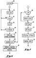
- FIG. 5 there is shown a more detailed flow diagram of an embodiment where changes corresponding to QT interval are utilized for determining LVD.
- the procedure for Figure 5 is adapted for a QT rate responsive pacemaker, where pacing rate is determined as a function of sensed QT interval.
- R f(QT)
- the changes in slope, and/or the change in correlation function are stored in memory.
- LR lowest heart rate
- LR is set equal to an initial valued LR 0 , which is a nominally high rate, i.e., above LRL.
- heart rate is determined, and at 82 the rate R is compared to LR. If R is less than LR at 83, LR is set equal to the new value R.
- the value of LR for the last day is stored. This is conveniently done by updating a histogram in memory which provides easily stored data giving a profile of different values of LR.
- FIG. 7 there is shown a flow diagram illustrating the primary steps of an algorithin for responding to a determination of LVD in a dual sensor pacemaker.
- U.S. Patent No. 5,065,759 which illustrates a dual chamber pacemaker for controlling pacing rate as a function of QT interval, and an activity signal (ACT) derived from an activity sensor.
- ACT activity signal
- the relative contribution of each of two or more rate-indicating parameters which are sensed by the pacemaker can be adjusted, or "blended.”
- the ACT sensor provides a faster but relatively less physiological response
- the QT interval provides a slower time response but a more physiological response to body changes.
- the pacemaker proceeds to control rate by setting the pacing interval in accordance with the composite rate response function. It is seen that in this way, by adapting the blending of two or more sensors, a more appropriate response to an LVD condition can be obtained and carried out automatically.
- this invention provides for determining a condition of heart failure such as LVD in a patient, by examination of cardiac signals.
- the scope of this invention reaches to processing any portion or portions of cardiac signals, from the RV or other chambers, to obtain information indicative of LVD.
- other signal variations can be examined, e.g., QRS or T-wave width, amplitude or morphology.
- the treatment response should be particularized for the individual patient, and can include changing the rate response algorithm, bi-ventricular pacing or other multi-chamber pacing, administration of drugs, etc.
Landscapes
- Health & Medical Sciences (AREA)
- Life Sciences & Earth Sciences (AREA)
- Cardiology (AREA)
- Heart & Thoracic Surgery (AREA)
- Nuclear Medicine, Radiotherapy & Molecular Imaging (AREA)
- Physiology (AREA)
- Engineering & Computer Science (AREA)
- Biomedical Technology (AREA)
- Biophysics (AREA)
- Radiology & Medical Imaging (AREA)
- Animal Behavior & Ethology (AREA)
- General Health & Medical Sciences (AREA)
- Public Health (AREA)
- Veterinary Medicine (AREA)
- Hematology (AREA)
- Electrotherapy Devices (AREA)
Priority Applications (1)
| Application Number | Priority Date | Filing Date | Title |
|---|---|---|---|
| EP01104717A EP1101509B1 (fr) | 1997-12-04 | 1998-12-03 | Système de stimulation implantable |
Applications Claiming Priority (2)
| Application Number | Priority Date | Filing Date | Title |
|---|---|---|---|
| US985127 | 1997-12-04 | ||
| US08/985,127 US6129744A (en) | 1997-12-04 | 1997-12-04 | Cardiac treatment system and method for sensing and responding to heart failure |
Related Child Applications (2)
| Application Number | Title | Priority Date | Filing Date |
|---|---|---|---|
| EP01104717A Division-Into EP1101509B1 (fr) | 1997-12-04 | 1998-12-03 | Système de stimulation implantable |
| EP01104717A Division EP1101509B1 (fr) | 1997-12-04 | 1998-12-03 | Système de stimulation implantable |
Publications (2)
| Publication Number | Publication Date |
|---|---|
| EP0920885A1 true EP0920885A1 (fr) | 1999-06-09 |
| EP0920885B1 EP0920885B1 (fr) | 2004-04-28 |
Family
ID=25531221
Family Applications (2)
| Application Number | Title | Priority Date | Filing Date |
|---|---|---|---|
| EP01104717A Expired - Lifetime EP1101509B1 (fr) | 1997-12-04 | 1998-12-03 | Système de stimulation implantable |
| EP98122974A Expired - Lifetime EP0920885B1 (fr) | 1997-12-04 | 1998-12-03 | Système de traitement cardiaque pour la détection et le traitement de défaillances cardiaques |
Family Applications Before (1)
| Application Number | Title | Priority Date | Filing Date |
|---|---|---|---|
| EP01104717A Expired - Lifetime EP1101509B1 (fr) | 1997-12-04 | 1998-12-03 | Système de stimulation implantable |
Country Status (3)
| Country | Link |
|---|---|
| US (1) | US6129744A (fr) |
| EP (2) | EP1101509B1 (fr) |
| DE (2) | DE69823459T2 (fr) |
Cited By (7)
| Publication number | Priority date | Publication date | Assignee | Title |
|---|---|---|---|---|
| EP1118307A1 (fr) * | 2000-01-19 | 2001-07-25 | Pacesetter, Inc. | Dispositif cardiaque implantable et méthode pour la surveillance de la progression ou de la regression des maladies cardiaques |
| WO2003041797A3 (fr) * | 2001-11-15 | 2003-10-23 | Cardiac Pacemakers Inc | Systeme permettant de determiner des changements au niveau de l'etat d'insuffisance cardiaque |
| WO2004096035A3 (fr) * | 2003-04-25 | 2005-01-13 | Medtronic Inc | Controle d'un complexe qrs en vue d'identifier une dysfonction du ventricule gauche |
| US6950708B2 (en) | 2000-01-21 | 2005-09-27 | Medtronic Minimed, Inc. | Ambulatory medical apparatus and method using a telemetry system with predefined reception listening |
| EP1595574A1 (fr) * | 2004-05-11 | 2005-11-16 | Pacesetter, Inc. | Système permettant l'évaluation de défaillances cardiaques |
| EP1218059A4 (fr) * | 1999-08-20 | 2009-04-15 | Impulse Dynamics Nv | Appareil et procede de commande de distribution au coeur de signaux non excitateurs modulateurs de la contractilite |
| US9248298B2 (en) | 2003-10-02 | 2016-02-02 | Medtronic, Inc. | Medical device programmer with selective disablement of display during telemetry |
Families Citing this family (58)
| Publication number | Priority date | Publication date | Assignee | Title |
|---|---|---|---|---|
| US7127290B2 (en) | 1999-10-01 | 2006-10-24 | Cardiac Pacemakers, Inc. | Cardiac rhythm management systems and methods predicting congestive heart failure status |
| US8744816B1 (en) * | 1999-11-08 | 2014-06-03 | Ryan G. Bosch | Evaluation of database records |
| US6942622B1 (en) | 1999-11-10 | 2005-09-13 | Pacesetter, Inc. | Method for monitoring autonomic tone |
| US6480733B1 (en) | 1999-11-10 | 2002-11-12 | Pacesetter, Inc. | Method for monitoring heart failure |
| US6473646B2 (en) * | 2000-04-18 | 2002-10-29 | Cardiac Pacemakers, Inc. | Method and apparatus for assessing cardiac functional status |
| US6572557B2 (en) * | 2000-05-09 | 2003-06-03 | Pacesetter, Inc. | System and method for monitoring progression of cardiac disease state using physiologic sensors |
| US6473647B1 (en) | 2000-10-18 | 2002-10-29 | Pacesetter, Inc. | Implantable cardiac stimulation device for and method of monitoring progression or regression of heart disease by monitoring evoked response features |
| US6622040B2 (en) | 2000-12-15 | 2003-09-16 | Cardiac Pacemakers, Inc. | Automatic selection of stimulation chamber for ventricular resynchronization therapy |
| US7181285B2 (en) * | 2000-12-26 | 2007-02-20 | Cardiac Pacemakers, Inc. | Expert system and method |
| US6804555B2 (en) * | 2001-06-29 | 2004-10-12 | Medtronic, Inc. | Multi-site ventricular pacing system measuring QRS duration |
| US6668194B2 (en) | 2001-07-16 | 2003-12-23 | Medtronic, Inc. | Method and apparatus for monitoring conduction times in a bi-chamber pacing system |
| US6871096B2 (en) * | 2001-10-26 | 2005-03-22 | Medtronic, Inc. | System and method for bi-ventricular fusion pacing |
| US20050027323A1 (en) * | 2001-10-30 | 2005-02-03 | Medtronic, Inc. | Implantable medical device for monitoring cardiac blood pressure and chamber dimension |
| US6671549B2 (en) * | 2001-11-16 | 2003-12-30 | Medtronic, Inc. | Pacemaker utilizing QT dynamics to diagnose heart failure |
| US6959214B2 (en) | 2001-11-28 | 2005-10-25 | Medtronic, Inc. | Implantable medical device for measuring mechanical heart function |
| DE10159461B4 (de) * | 2001-12-04 | 2005-03-03 | Preh Gmbh | Vorrichtung zur Halterung von Behältern, insbesondere von Getränkebehältern |
| US6865420B1 (en) | 2002-01-14 | 2005-03-08 | Pacesetter, Inc. | Cardiac stimulation device for optimizing cardiac output with myocardial ischemia protection |
| US6952612B1 (en) | 2002-04-24 | 2005-10-04 | Pacesetter, Inc. | Method and apparatus for programming a rate responsive implantable cardiac stimulation device using user specified rate response functions |
| SE0201822D0 (sv) * | 2002-06-14 | 2002-06-14 | St Jude Medical | A heart monitoring and stimulating device, a system including such a device and use of the system |
| US6922587B2 (en) * | 2002-06-26 | 2005-07-26 | Pacesetter, Inc. | System and method for tracking progression of left ventricular dysfunction using implantable cardiac stimulation device |
| US7835791B2 (en) * | 2002-08-05 | 2010-11-16 | Fujikin Incorporated | Medical treatment system using biological regulation function alternate, cardiac pacing system based on the medical treatment system, blood pressure regulating system, and cardiac disease treating system |
| US7305265B2 (en) * | 2002-11-25 | 2007-12-04 | Terumo Kabushiki Kaisha | Heart treatment equipment for treating heart failure |
| US7136707B2 (en) | 2003-01-21 | 2006-11-14 | Cardiac Pacemakers, Inc. | Recordable macros for pacemaker follow-up |
| US6889083B2 (en) * | 2003-04-21 | 2005-05-03 | Medtronic, Inc. | Atrial tracking recovery to restore cardiac resynchronization therapy in dual chamber tracking modes |
| US7558626B2 (en) * | 2003-04-23 | 2009-07-07 | Medtronic, Inc. | Cardiac resynchronization via left ventricular pacing |
| US7613513B1 (en) | 2003-07-01 | 2009-11-03 | Pacesetter, Inc. | System and method for determining cardiac geometry |
| US7003348B1 (en) | 2003-07-01 | 2006-02-21 | Pacesetter, Inc. | Monitoring cardiac geometry for diagnostics and therapy |
| US7027866B2 (en) | 2003-07-29 | 2006-04-11 | Medtronic, Inc. | Mechanically-based interval optimization for a biventricular pacing engine |
| US7123960B2 (en) | 2003-12-22 | 2006-10-17 | Cardiac Pacemakers, Inc. | Method and system for delivering cardiac resynchronization therapy with variable atrio-ventricular delay |
| US7203540B2 (en) * | 2003-12-22 | 2007-04-10 | Cardiac Pacemakers, Inc. | Method and system for setting cardiac resynchronization therapy parameters |
| US7499746B2 (en) | 2004-01-30 | 2009-03-03 | Encore Medical Asset Corporation | Automated adaptive muscle stimulation method and apparatus |
| US7142920B2 (en) * | 2004-05-25 | 2006-11-28 | Cardiac Pacemakers, Inc. | Chronotropic status monitor for implantable cardiac device |
| US7269458B2 (en) * | 2004-08-09 | 2007-09-11 | Cardiac Pacemakers, Inc. | Cardiopulmonary functional status assessment via heart rate response detection by implantable cardiac device |
| US7389143B2 (en) | 2004-08-12 | 2008-06-17 | Cardiac Pacemakers, Inc. | Cardiopulmonary functional status assessment via metabolic response detection by implantable cardiac device |
| US7386345B2 (en) * | 2005-01-27 | 2008-06-10 | Cardiac Pacemakers, Inc. | Apparatus and method for temporary treatment of acute heart failure decompensation |
| US20070021678A1 (en) * | 2005-07-19 | 2007-01-25 | Cardiac Pacemakers, Inc. | Methods and apparatus for monitoring physiological responses to steady state activity |
| US7899522B1 (en) * | 2006-10-13 | 2011-03-01 | Pacesetter, Inc. | System and method for discriminating acute and chronic heart failure using an implantable medical device |
| US7676264B1 (en) | 2007-04-13 | 2010-03-09 | Pacesetter, Inc. | Systems and methods for use by an implantable medical device for evaluating ventricular dyssynchrony based on T-wave morphology |
| WO2009036306A1 (fr) | 2007-09-14 | 2009-03-19 | Corventis, Inc. | Moniteur cardiaque adhérent doté de capacités avancées de détection |
| EP2194847A1 (fr) | 2007-09-14 | 2010-06-16 | Corventis, Inc. | Dispositif adhérent avec de multiples capteurs physiologiques |
| WO2009036348A1 (fr) | 2007-09-14 | 2009-03-19 | Corventis, Inc. | Démarrage automatique d'un dispositif médical au contact d'un tissu d'un patient |
| WO2009036316A1 (fr) | 2007-09-14 | 2009-03-19 | Corventis, Inc. | Gestion d'énergie, suivi et sécurité pour un moniteur de patient adhérent |
| US8684925B2 (en) | 2007-09-14 | 2014-04-01 | Corventis, Inc. | Injectable device for physiological monitoring |
| US8374688B2 (en) | 2007-09-14 | 2013-02-12 | Corventis, Inc. | System and methods for wireless body fluid monitoring |
| EP2200512A1 (fr) | 2007-09-14 | 2010-06-30 | Corventis, Inc. | Dispositif adhérent pour la surveillance de la respiration et de troubles respiratoires pendant le sommeil |
| JP5405500B2 (ja) | 2008-03-12 | 2014-02-05 | コーヴェンティス,インク. | 心調律に基づく心代償不全予測 |
| US8412317B2 (en) | 2008-04-18 | 2013-04-02 | Corventis, Inc. | Method and apparatus to measure bioelectric impedance of patient tissue |
| US8521277B2 (en) * | 2008-09-04 | 2013-08-27 | Pacesetter, Inc. | Implantable systems and method for use therewith for tracking changes in hemodynamics and cardiac disease |
| JP5559810B2 (ja) | 2008-12-15 | 2014-07-23 | コーヴェンティス,インク. | 患者モニタリングシステムおよび方法 |
| WO2011050283A2 (fr) | 2009-10-22 | 2011-04-28 | Corventis, Inc. | Détection et surveillance à distance de l'incompétence chronotrope fonctionnelle |
| US9538922B2 (en) * | 2009-10-30 | 2017-01-10 | Medtronic, Inc. | Monitoring an interval within the cardiac cycle |
| US9451897B2 (en) | 2009-12-14 | 2016-09-27 | Medtronic Monitoring, Inc. | Body adherent patch with electronics for physiologic monitoring |
| US8965498B2 (en) | 2010-04-05 | 2015-02-24 | Corventis, Inc. | Method and apparatus for personalized physiologic parameters |
| US8600504B2 (en) | 2010-07-02 | 2013-12-03 | Cardiac Pacemakers, Inc. | Physiologic demand driven pacing |
| EP2564897A1 (fr) | 2011-08-31 | 2013-03-06 | St. Jude Medical AB | Système pour déterminer les paramètres de stimulation |
| US8954138B2 (en) | 2011-11-16 | 2015-02-10 | Cardiac Pacemakers, Inc. | Using device based electrograms to identify bundle branch block morphology |
| US10058708B2 (en) | 2015-06-30 | 2018-08-28 | Cardiac Pacemakers, Inc. | Heart failure event detection using minimum heart rate |
| US11707628B2 (en) | 2019-05-30 | 2023-07-25 | Medtronic, Inc. | Rate responsive pacing |
Citations (9)
| Publication number | Priority date | Publication date | Assignee | Title |
|---|---|---|---|---|
| US4401120A (en) | 1978-11-06 | 1983-08-30 | Medtronic, Inc. | Digital cardiac pacemaker with program acceptance indicator |
| US4550370A (en) | 1982-10-29 | 1985-10-29 | Medtronic, Inc. | Pacemaker programmer with telemetric functions |
| US4556063A (en) | 1980-10-07 | 1985-12-03 | Medtronic, Inc. | Telemetry system for a medical device |
| US4972834A (en) | 1988-09-30 | 1990-11-27 | Vitatron Medical B.V. | Pacemaker with improved dynamic rate responsiveness |
| US5065759A (en) | 1990-08-30 | 1991-11-19 | Vitatron Medical B.V. | Pacemaker with optimized rate responsiveness and method of rate control |
| EP0467695A2 (fr) * | 1990-07-20 | 1992-01-22 | Telectronics N.V. | Détection et traitement des infarctus du myocarde dans un stimulateur antitachy-arythmie et bradycardie |
| EP0487429A1 (fr) * | 1990-11-23 | 1992-05-27 | Fred Zacouto | Dispositif de prévention des défaillances cardiaques |
| EP0541338A1 (fr) * | 1991-11-04 | 1993-05-12 | Cardiac Pacemakers, Inc. | Appareil implantable de surveillance et de stimulation cardiaque pour diagnostic et thérapie |
| EP0804939A2 (fr) * | 1996-04-29 | 1997-11-05 | Pacesetter, Inc. | Utilisation du volume-minute pour classer l'état cardiaque d'un patient dans un dispositif implanté |
Family Cites Families (7)
| Publication number | Priority date | Publication date | Assignee | Title |
|---|---|---|---|---|
| US5014698A (en) * | 1987-10-06 | 1991-05-14 | Leonard Bloom | Method of and system for monitoring and treating a malfunctioning heart |
| US5782890A (en) * | 1992-07-01 | 1998-07-21 | Medtronic, Inc. | Method for heart transplant monitoring and analog telemetry calibration |
| US5560368A (en) * | 1994-11-15 | 1996-10-01 | Berger; Ronald D. | Methodology for automated QT variability measurement |
| US5700283A (en) * | 1996-11-25 | 1997-12-23 | Cardiac Pacemakers, Inc. | Method and apparatus for pacing patients with severe congestive heart failure |
| US5902324A (en) * | 1998-04-28 | 1999-05-11 | Medtronic, Inc. | Bi-atrial and/or bi-ventricular sequential cardiac pacing systems |
| US6021351A (en) * | 1998-05-11 | 2000-02-01 | Cardiac Pacemakers, Inc. | Method and apparatus for assessing patient well-being |
| US6045513A (en) * | 1998-05-13 | 2000-04-04 | Medtronic, Inc. | Implantable medical device for tracking patient functional status |
-
1997
- 1997-12-04 US US08/985,127 patent/US6129744A/en not_active Expired - Lifetime
-
1998
- 1998-12-03 EP EP01104717A patent/EP1101509B1/fr not_active Expired - Lifetime
- 1998-12-03 DE DE69823459T patent/DE69823459T2/de not_active Expired - Lifetime
- 1998-12-03 EP EP98122974A patent/EP0920885B1/fr not_active Expired - Lifetime
- 1998-12-03 DE DE69832639T patent/DE69832639T2/de not_active Expired - Lifetime
Patent Citations (9)
| Publication number | Priority date | Publication date | Assignee | Title |
|---|---|---|---|---|
| US4401120A (en) | 1978-11-06 | 1983-08-30 | Medtronic, Inc. | Digital cardiac pacemaker with program acceptance indicator |
| US4556063A (en) | 1980-10-07 | 1985-12-03 | Medtronic, Inc. | Telemetry system for a medical device |
| US4550370A (en) | 1982-10-29 | 1985-10-29 | Medtronic, Inc. | Pacemaker programmer with telemetric functions |
| US4972834A (en) | 1988-09-30 | 1990-11-27 | Vitatron Medical B.V. | Pacemaker with improved dynamic rate responsiveness |
| EP0467695A2 (fr) * | 1990-07-20 | 1992-01-22 | Telectronics N.V. | Détection et traitement des infarctus du myocarde dans un stimulateur antitachy-arythmie et bradycardie |
| US5065759A (en) | 1990-08-30 | 1991-11-19 | Vitatron Medical B.V. | Pacemaker with optimized rate responsiveness and method of rate control |
| EP0487429A1 (fr) * | 1990-11-23 | 1992-05-27 | Fred Zacouto | Dispositif de prévention des défaillances cardiaques |
| EP0541338A1 (fr) * | 1991-11-04 | 1993-05-12 | Cardiac Pacemakers, Inc. | Appareil implantable de surveillance et de stimulation cardiaque pour diagnostic et thérapie |
| EP0804939A2 (fr) * | 1996-04-29 | 1997-11-05 | Pacesetter, Inc. | Utilisation du volume-minute pour classer l'état cardiaque d'un patient dans un dispositif implanté |
Non-Patent Citations (1)
| Title |
|---|
| CAZEAQ ET AL.: "Four Chamber Pacing in Dilated Cardiomyopathy", PACE, vol. 17, no. II, November 1994 (1994-11-01) |
Cited By (16)
| Publication number | Priority date | Publication date | Assignee | Title |
|---|---|---|---|---|
| EP1218059A4 (fr) * | 1999-08-20 | 2009-04-15 | Impulse Dynamics Nv | Appareil et procede de commande de distribution au coeur de signaux non excitateurs modulateurs de la contractilite |
| EP1118307A1 (fr) * | 2000-01-19 | 2001-07-25 | Pacesetter, Inc. | Dispositif cardiaque implantable et méthode pour la surveillance de la progression ou de la regression des maladies cardiaques |
| US7069069B2 (en) | 2000-01-19 | 2006-06-27 | Pacesetter, Inc. | Implantable cardiac device for and method of monitoring progression or regression of heart disease by quantifying morphological features |
| US6950708B2 (en) | 2000-01-21 | 2005-09-27 | Medtronic Minimed, Inc. | Ambulatory medical apparatus and method using a telemetry system with predefined reception listening |
| US8568356B2 (en) | 2000-01-21 | 2013-10-29 | Medtronic Minimed, Inc. | Ambulatory medical apparatus with hand held communication device |
| US7024245B2 (en) | 2000-01-21 | 2006-04-04 | Medtronic Minimed, Inc. | Ambulatory medical apparatus and method using a robust communication protocol |
| US7678071B2 (en) | 2000-01-21 | 2010-03-16 | Medtronic Minimed, Inc. | Microprocessor controlled ambulatory medical apparatus with hand held communication device |
| US7831310B2 (en) | 2000-01-21 | 2010-11-09 | Medtronic Minimed, Inc. | Microprocessor controlled ambulatory medical apparatus with hand held communication device |
| US6980851B2 (en) | 2001-11-15 | 2005-12-27 | Cardiac Pacemakers, Inc. | Method and apparatus for determining changes in heart failure status |
| WO2003041797A3 (fr) * | 2001-11-15 | 2003-10-23 | Cardiac Pacemakers Inc | Systeme permettant de determiner des changements au niveau de l'etat d'insuffisance cardiaque |
| US7769437B2 (en) | 2001-11-15 | 2010-08-03 | Cardiac Pacemakers, Inc. | Method and apparatus for determining changes in heart failure status |
| WO2004096035A3 (fr) * | 2003-04-25 | 2005-01-13 | Medtronic Inc | Controle d'un complexe qrs en vue d'identifier une dysfonction du ventricule gauche |
| US7930026B2 (en) | 2003-04-25 | 2011-04-19 | Medtronic, Inc. | Monitoring QRS complex to identify left ventricular dysfunction |
| US9248298B2 (en) | 2003-10-02 | 2016-02-02 | Medtronic, Inc. | Medical device programmer with selective disablement of display during telemetry |
| EP1595574A1 (fr) * | 2004-05-11 | 2005-11-16 | Pacesetter, Inc. | Système permettant l'évaluation de défaillances cardiaques |
| US7171271B2 (en) | 2004-05-11 | 2007-01-30 | Pacesetter, Inc. | System and method for evaluating heart failure using an implantable medical device based on heart rate during patient activity |
Also Published As
| Publication number | Publication date |
|---|---|
| DE69832639T2 (de) | 2006-08-10 |
| DE69823459D1 (de) | 2004-06-03 |
| DE69823459T2 (de) | 2005-04-14 |
| EP1101509B1 (fr) | 2005-11-30 |
| EP0920885B1 (fr) | 2004-04-28 |
| US6129744A (en) | 2000-10-10 |
| EP1101509A1 (fr) | 2001-05-23 |
| DE69832639D1 (de) | 2006-01-05 |
Similar Documents
| Publication | Publication Date | Title |
|---|---|---|
| US6129744A (en) | Cardiac treatment system and method for sensing and responding to heart failure | |
| EP1610859B1 (fr) | Appareil d `evaluation et d `optimisation de la synchronisation ventriculaire | |
| US6922587B2 (en) | System and method for tracking progression of left ventricular dysfunction using implantable cardiac stimulation device | |
| US8712521B2 (en) | Method and apparatus for controlling cardiac resynchronization therapy using cardiac impedance | |
| USRE42836E1 (en) | Method for assessing cardiac functional status | |
| US6711439B1 (en) | Evoked response variability as an indicator of autonomic tone and surrogate for patient condition | |
| US6804555B2 (en) | Multi-site ventricular pacing system measuring QRS duration | |
| US7130684B2 (en) | Method and apparatus for improving ventricular status using the force interval relationship | |
| EP0929344B1 (fr) | Dispositif implantable | |
| US7103403B1 (en) | Implantable cardiac stimulation system and method for monitoring diastolic function | |
| US20010037067A1 (en) | System and method for monitoring progression of cardiac disease state using physiologic sensors | |
| US7069078B2 (en) | Insulin-mediated glucose uptake monitor | |
| EP3806951B1 (fr) | Administration d'une thérapie de stimulation cardiaque pour remodelage cardiaque | |
| EP3806950B1 (fr) | Administration d'une thérapie de stimulation cardiaque pour un remodelage cardiaque | |
| EP3989801B1 (fr) | Évaluation de la récupération de la fréquence cardiaque | |
| US8391978B2 (en) | Method and apparatus for adjusting sensitivity using intracardiac pressure data | |
| US7930026B2 (en) | Monitoring QRS complex to identify left ventricular dysfunction | |
| US7917194B1 (en) | Method and apparatus for detecting pulmonary edema | |
| US7894901B1 (en) | Apparatus and method for assessing cardiac therapy | |
| EP1430927A1 (fr) | Dispositif de stimulation du coeur, système avec un tel dispositif et utilisation de ce système | |
| US20090281588A1 (en) | Determining atrial time periods in conjunction with real-time testing |
Legal Events
| Date | Code | Title | Description |
|---|---|---|---|
| PUAI | Public reference made under article 153(3) epc to a published international application that has entered the european phase |
Free format text: ORIGINAL CODE: 0009012 |
|
| AK | Designated contracting states |
Kind code of ref document: A1 Designated state(s): CH DE FR LI NL SE |
|
| AX | Request for extension of the european patent |
Free format text: AL;LT;LV;MK;RO;SI |
|
| 17P | Request for examination filed |
Effective date: 19991109 |
|
| AKX | Designation fees paid |
Free format text: CH DE FR LI NL SE |
|
| 17Q | First examination report despatched |
Effective date: 20000830 |
|
| GRAP | Despatch of communication of intention to grant a patent |
Free format text: ORIGINAL CODE: EPIDOSNIGR1 |
|
| GRAS | Grant fee paid |
Free format text: ORIGINAL CODE: EPIDOSNIGR3 |
|
| GRAA | (expected) grant |
Free format text: ORIGINAL CODE: 0009210 |
|
| AK | Designated contracting states |
Kind code of ref document: B1 Designated state(s): CH DE FR LI NL SE |
|
| REG | Reference to a national code |
Ref country code: CH Ref legal event code: EP |
|
| REF | Corresponds to: |
Ref document number: 69823459 Country of ref document: DE Date of ref document: 20040603 Kind code of ref document: P |
|
| REG | Reference to a national code |
Ref country code: SE Ref legal event code: TRGR |
|
| REG | Reference to a national code |
Ref country code: CH Ref legal event code: NV Representative=s name: ISLER & PEDRAZZINI AG |
|
| PG25 | Lapsed in a contracting state [announced via postgrant information from national office to epo] |
Ref country code: SE Free format text: LAPSE BECAUSE OF NON-PAYMENT OF DUE FEES Effective date: 20041204 |
|
| ET | Fr: translation filed | ||
| PLBE | No opposition filed within time limit |
Free format text: ORIGINAL CODE: 0009261 |
|
| STAA | Information on the status of an ep patent application or granted ep patent |
Free format text: STATUS: NO OPPOSITION FILED WITHIN TIME LIMIT |
|
| 26N | No opposition filed |
Effective date: 20050131 |
|
| EUG | Se: european patent has lapsed | ||
| PGFP | Annual fee paid to national office [announced via postgrant information from national office to epo] |
Ref country code: CH Payment date: 20061026 Year of fee payment: 9 |
|
| REG | Reference to a national code |
Ref country code: CH Ref legal event code: PCAR Free format text: ISLER & PEDRAZZINI AG;POSTFACH 1772;8027 ZUERICH (CH) |
|
| PGFP | Annual fee paid to national office [announced via postgrant information from national office to epo] |
Ref country code: NL Payment date: 20071109 Year of fee payment: 10 |
|
| REG | Reference to a national code |
Ref country code: CH Ref legal event code: PL |
|
| PG25 | Lapsed in a contracting state [announced via postgrant information from national office to epo] |
Ref country code: LI Free format text: LAPSE BECAUSE OF NON-PAYMENT OF DUE FEES Effective date: 20071231 Ref country code: CH Free format text: LAPSE BECAUSE OF NON-PAYMENT OF DUE FEES Effective date: 20071231 |
|
| NLV4 | Nl: lapsed or anulled due to non-payment of the annual fee |
Effective date: 20090701 |
|
| PG25 | Lapsed in a contracting state [announced via postgrant information from national office to epo] |
Ref country code: NL Free format text: LAPSE BECAUSE OF NON-PAYMENT OF DUE FEES Effective date: 20090701 |
|
| PGFP | Annual fee paid to national office [announced via postgrant information from national office to epo] |
Ref country code: DE Payment date: 20131230 Year of fee payment: 16 |
|
| PGFP | Annual fee paid to national office [announced via postgrant information from national office to epo] |
Ref country code: FR Payment date: 20131217 Year of fee payment: 16 |
|
| REG | Reference to a national code |
Ref country code: DE Ref legal event code: R119 Ref document number: 69823459 Country of ref document: DE |
|
| REG | Reference to a national code |
Ref country code: FR Ref legal event code: ST Effective date: 20150831 |
|
| PG25 | Lapsed in a contracting state [announced via postgrant information from national office to epo] |
Ref country code: DE Free format text: LAPSE BECAUSE OF NON-PAYMENT OF DUE FEES Effective date: 20150701 |
|
| PG25 | Lapsed in a contracting state [announced via postgrant information from national office to epo] |
Ref country code: FR Free format text: LAPSE BECAUSE OF NON-PAYMENT OF DUE FEES Effective date: 20141231 |