EP0920903A1 - Système biofiltre - Google Patents
Système biofiltre Download PDFInfo
- Publication number
- EP0920903A1 EP0920903A1 EP98122221A EP98122221A EP0920903A1 EP 0920903 A1 EP0920903 A1 EP 0920903A1 EP 98122221 A EP98122221 A EP 98122221A EP 98122221 A EP98122221 A EP 98122221A EP 0920903 A1 EP0920903 A1 EP 0920903A1
- Authority
- EP
- European Patent Office
- Prior art keywords
- gas
- modules
- water
- biofilter system
- filter material
- Prior art date
- Legal status (The legal status is an assumption and is not a legal conclusion. Google has not performed a legal analysis and makes no representation as to the accuracy of the status listed.)
- Withdrawn
Links
Images

Classifications
-
- B—PERFORMING OPERATIONS; TRANSPORTING
- B01—PHYSICAL OR CHEMICAL PROCESSES OR APPARATUS IN GENERAL
- B01D—SEPARATION
- B01D53/00—Separation of gases or vapours; Recovering vapours of volatile solvents from gases; Chemical or biological purification of waste gases, e.g. engine exhaust gases, smoke, fumes, flue gases, aerosols
- B01D53/34—Chemical or biological purification of waste gases
- B01D53/74—General processes for purification of waste gases; Apparatus or devices specially adapted therefor
- B01D53/84—Biological processes
- B01D53/85—Biological processes with gas-solid contact
-
- Y—GENERAL TAGGING OF NEW TECHNOLOGICAL DEVELOPMENTS; GENERAL TAGGING OF CROSS-SECTIONAL TECHNOLOGIES SPANNING OVER SEVERAL SECTIONS OF THE IPC; TECHNICAL SUBJECTS COVERED BY FORMER USPC CROSS-REFERENCE ART COLLECTIONS [XRACs] AND DIGESTS
- Y02—TECHNOLOGIES OR APPLICATIONS FOR MITIGATION OR ADAPTATION AGAINST CLIMATE CHANGE
- Y02A—TECHNOLOGIES FOR ADAPTATION TO CLIMATE CHANGE
- Y02A50/00—TECHNOLOGIES FOR ADAPTATION TO CLIMATE CHANGE in human health protection, e.g. against extreme weather
- Y02A50/20—Air quality improvement or preservation, e.g. vehicle emission control or emission reduction by using catalytic converters
Definitions
- the invention relates to a biofilter system for gas cleaning, consisting of a housing with gas inlet and gas outlet openings as well as a recording room arranged in between for taking up a biologically active filter material, the gas volume flow of the gas to be cleaned through the Recording space is guided over the filter material.
- Such filter systems are used in various areas where gaseous and / or liquid exhaust air components too are eliminated, for example for exhaust air treatment in production processes, for the remediation of contaminated sites for cleaning of polluted soil air, for cleaning exhaust air in paint shops or for air purification or exhaust air deodorization factory farming.
- the receiving space consists of a container in the bottom area, for example, at the lower end of a side wall, a gas inlet opening and a gas outlet opening in its upper area having.
- a container is used for gas cleaning with a biologically active filter material like bark mulch, Compost, peat or the like, optionally together with porous mineral components such as volcanic rock or the like.
- the gas to be cleaned will passed through the biologically active filter material, whereby contaminants carried along with the gas stream from the filter material are retained or in the filter material existing bacteria converted to carbon dioxide and water become.
- the biologically active filter material is usually in a layer height of 150 to 180 cm. All in all considerable amounts of filter material are therefore necessary. It turned out that due to the necessary large layer height of filter material this in the course of Time compressed by its own weight, making the active Surface that is decisive for the cleaning performance, is reduced.
- a further disadvantage of such filter systems is that they cannot be adapted to different gas volume flows and exhaust air compositions.
- the layer height of filter material in the container can be varied, the container always has the same space requirement, even if it is only loaded with a comparatively small amount of filter material. Since the containers are usually designed for an intake of approx. 20 m 3 of biomaterial, this also results in correspondingly high investment costs.
- the object of the present invention is therefore a biofilter system to create the optimal use of the cleaning ability of the filter material and with as possible low design effort for different gas volume flows and compositions are customizable.
- the object is achieved in that the receiving space of the biofilter system in at least two gas flows Is divided into compartments, each accommodating Filter material are used, the chambers fluidically are connected in series. This makes it possible to the joining of any number of filter chambers to create a biofilter system that expands almost arbitrarily can be and thus easily to different Gas volume flows or loads on the gas to be cleaned is customizable.
- the required amount of filter material on different chambers be distributed, with the gas volume flow in succession is led through the chambers.
- the fact that in each filter chamber only a comparatively small amount of filter material is present and accordingly in each chamber taking up only a small layer height becomes a compaction of the filter material due to the weight of the filter material with high layer thicknesses and thus a reduction surface activity avoided. That of the one to be cleaned Rather, filter material through which gas flows can always be in one comparatively loose layering with a high active surface are present so that an optimal use of the cleaning effect is possible.
- the individual filter chambers arranged one above the other and through horizontal shelves separately, on which the filter material can be arranged is.
- the filter material can both spread in bulk on the intermediate floors as can also be arranged in suitable receptacles.
- the partition wall or the intermediate floor is advantageous the chambers are gas permeable, so that a special simple gas flow in the vertical direction is possible. Possibly can also be the gas to be cleaned essentially introduced into the filter chambers parallel to the intermediate floors become.
- Gas permeable shelves can be used as grids, Perforated sheets or the like may be carried out, if necessary depending on the grain size of the filter material with inserts such as close-meshed nets and the like are.
- the dividers or intermediate shelves are to be made possible easy to disassemble, for example only loosely on the corresponding one Holders attached.
- the Filter chambers of the biofilter system in the form of separate modules executed, the detachable and gastight attachable to each other and are successively flowed through by the gas to be cleaned become.
- the modules can, for example, by means of tension connections such as clasps or the like attached to each other be and sealed by means of O-ring seals.
- the modules can each have a gas-permeable, advantageously removable bottom and a Have open top, with the top and bottom sides the modules can be connected to each other in a gas-tight manner and the modules to one another are attachable.
- the gas permeable bottom of a The module can extend over its entire base area. If necessary, a separate support structure can be provided or it can attached modules supported on a support structure to be arranged especially in a vertically Biofilter system to maintain sufficient stability.
- the ratio of the diameter of the base of a chamber their height can be between 1.5: 1 to 2.5: 1, preferably 2: 1, amount, where appropriate, larger or smaller ratios can be provided.
- the biofilter system can be varied within wide limits is and at the same time a comparatively small amount of Filter material can be maintained, so practical no compression of the filter material occurs.
- the housing can a separate head and / or foot section with gas inlet or Have gas outlet opening, with head or foot part with the top or bottom of the modules can be connected gastight are.
- the gas inlet has proven to be particularly advantageous in the upper part of the housing and the gas outlet in the lower part to arrange the housing.
- This is a fluidic given particularly favorable gas flow, in which the gas to be cleaned is optimally distributed in the biofilter system and the entire filter volume is used. This is particularly so then the case when a gas humidifier is provided is to moisten the filter material.
- a gas humidifier By an optimal Humidification can reduce the cleaning capacity of the filter material be improved, especially if the gas cleaning Activity of bacteria is important because it is in the Usually takes place in the aqueous phase.
- Gas humidification can be achieved, for example, by injecting water or the like, but mostly only soft or demineralized water can be used and due to the Evaporation of the water, the gas to be cleaned is cooled.
- a water holding container is advantageously used for gas humidification used with a gas inlet and a gas outlet, the gas to be humidified above the water surface is led or passed through the water.
- gas humidification used with a gas inlet and a gas outlet
- the gas to be humidified above the water surface is led or passed through the water.
- the superheated can also be used for gas humidification Gas can be passed over or through a water reservoir.
- the gas humidifier advantageously has means by means of the gas to be humidified above the water surface is swirled or the water surface is enlarged. This can be done above the water surface between gas entry and gas outlet a baffle plate may be provided, which is minor ends above the water surface, or the water surface can be whirled up by stirrers or the like become.
- the Water temperature 1.5 to 1.8 times the temperature of the gas volume flow is.
- the temperature of the to be cleaned Gases set to about 25 to 35 ° C, so the Water temperature of the gas humidifier preferably 50 to 60 ° C.
- the Water storage tank of the gas humidifier a water storage tank be assigned, depending on the level supplies this water in the water holding tank. This can a simple float control can be provided.
- this is advantageously the water storage tank again of the gas humidifier and / or the water reservoir fed.
- the water reservoir can do so be dimensioned so that it has a dead space, so that the maximum water volume accumulating in the foot part of the biofilter system can be accommodated by the storage container, too if this is the maximum for filling the gas humidifier Level has reached.
- biofilter systems are often installed outdoors can be in the foot part of the housing as well as in the Water reservoir heaters may be provided so that a adequate frost protection is guaranteed.
- the 1 consists of a housing 1, that consists of several filter chambers in the form of detachable and gas-tight interconnected modules 2 is composed.
- the modules 2 each have a cylindrical side wall 3; they are each gas-permeable towards the bottom
- Intermediate floor 4 is limited and is open on its upper side 6 executed.
- the intermediate floor 4 is in each case a perforated plate executed and on a cross-sectional constriction of module 2 loosely applied.
- the large-volume and more or less coarse-grained biologically active filter material be piled up, for example compost, bark mulch, Contains peat, lava slag or the like.
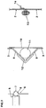
- the modules can be connected in different ways Way. In Fig. 2 are a few examples shown.
- a first embodiment (Fig. 2, left) are the modules on the underside with a recessed paragraph 5 and on its top 6 with an outwardly projecting Provide area 7 which serves to receive an O-ring 8.
- An intermediate floor 4 can be placed on the section 5.
- the cantilevered area 7 forms a groove with its free End partially overlaps the O-ring 8.
- the O-ring 8 is thereby at the bottom of the groove and on the groove flanks.
- the lower paragraph 5 of a module is dimensioned so that this can be used in the O-ring, so that the O-ring Seals the connection area of the modules.
- the two modules can with each other by clamping rings or clamps get connected.
- Fig. 2, middle are the Side walls 3 of the modules on the upper and lower end faces provided with outwardly projecting areas 9, which are in one piece here are molded and preferably over the entire Extend scope.
- the side wall 3 of the module is with a inwardly recessed, full-length connector 10 extended downwards, which in the lower module with little Game is plugged in and on the intermediate floor can be hung up.
- a sealing ring 11 are arranged, which by one of the two collars 9 acting clamping ring 12 sealing against the collar as well as the connector.
- the modules 2 can also, according to FIG. 2, right, by means of a Flange connection 13 are attached to each other, which is also a May have sealing element.
- a Flange connection 13 On the inside wall of the module an angle piece 14 is arranged, the support of intermediate floors serves.
- the filter column formed by the modules is, as in Fig. 1, by a head part 15 with a gas inlet connection 16 and by a foot part 17 with a gas outlet connection 18 completed, with head and foot 15, 17 with the adjacent modules 2 are connected gas-tight.
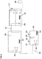
- the gas inlet port 16 of the biofilter is a gas humidifier 30 upstream, as can be seen in Fig. 3.
- the gas humidifier has a water reservoir 20 and one this gas-tightly closing and removable cover plate 21 on, which are provided with a gas inlet 22 and a gas outlet 23. Between the gas inlet and the gas outlet is in the flow area a baffle 24 of the gas to be humidified.
- the water reservoir is filled so that the Water surface at least 50 mm below the baffle stands.
- the water level in the receptacle 20 can by the float circuit 25 can be set using a fill valve operated on a water reservoir. Because of that Flow area of the gas protruding baffle this swirls above the water surface, causing the Humidification of the gas is improved.
- the water holding container 20 is gas humidifier heatable by a heater 32 arranged in the interior thereof. This is designed so that a water temperature of 50 to 60 ° C is easily accessible. Through the gas humidifier the relative humidity of the gas to be cleaned to 100 % or even higher if due to the Gas volume flow and the narrow guidance over the water surface Water components are carried away.
- this is liquid-carrying with a storage container 26 connected, for example 200 l of water Can accommodate, the water delivery to the water storage tank 20 takes place over a natural gradient.
- a storage container 26 is also provided with a heater 31, which essentially serves as frost protection, as well as with a float circuit 33 that the water inlet from the Local network or another water reservoir regulates.
- the water in the storage container may also be caused by bacteria be vaccinated, which are effective in the biofilter system.
- the reservoir 26 can also via the process water return 27 accumulated in the foot part 17 of the filter system Absorb water.
- a feed pump 28 is provided in the base part 17 of the housing, which depending on the level in the foot part 17 a corresponding control 29 regulates the storage container 26 supplies water.
- the controller 29 is protected against dry running equipped for the pump 28.
- the water intake volume of the reservoir 26 is dimensioned so that the via the float circuit 33 maximum predetermined level the total amount of process water accumulated in the foot part 17 can be included. An overfill of the storage container 26 is therefore excluded.
- the gas to be cleaned emerging from the gas humidifier the a temperature between 20 to 40 ° C, preferably between 25 to 35 ° C, is on the nozzle 16 in the head part 15th of the biofilter system. Due to the cross-sectional expansion of the flow channel and the high relative humidity water separates from the gas to be cleaned from that due to the swirling airflow in the headboard is evenly distributed over the cross-section of the modules and due to the gas flow as well as gravity in vertical Direction descending the filter material arranged in the modules evenly moistened. Differences in humidity over the height of the biofilter system is avoided.
- the biofilter system according to the invention can consist of cylindrical ones Modules exist, e.g. a diameter of 700 mm as well have a height of 365 mm.
- 3 to 10 modules to a filter system be summarized, with the upper limit essentially determined due to the decreasing mechanical stability is.
- the filter material is preferably in the modules in a stratification of 70 to 90%, for example 80%, loaded, so that at one Module height of 365 mm results in a layer height of 300 mm.
- the biofilter system according to the invention is mostly operated with a low gas overpressure of up to approx. 0.5 bar, mostly approx. 0.3 bar and can, for example, have an air volume flow of 500 to 1000 m 3 / h with a solvent load of approx. 1000 mg / m 3 clean. This significantly improves the cleaning capacity per unit volume compared to conventional biofilter systems.
- Biofilter systems can be operated in parallel.
Landscapes
- Engineering & Computer Science (AREA)
- Health & Medical Sciences (AREA)
- Biomedical Technology (AREA)
- Environmental & Geological Engineering (AREA)
- Chemical & Material Sciences (AREA)
- Life Sciences & Earth Sciences (AREA)
- Molecular Biology (AREA)
- Analytical Chemistry (AREA)
- General Chemical & Material Sciences (AREA)
- Oil, Petroleum & Natural Gas (AREA)
- Chemical Kinetics & Catalysis (AREA)
- Separation Using Semi-Permeable Membranes (AREA)
Applications Claiming Priority (2)
| Application Number | Priority Date | Filing Date | Title |
|---|---|---|---|
| DE19753409A DE19753409A1 (de) | 1997-12-02 | 1997-12-02 | Biofiltersystem |
| DE19753409 | 1997-12-02 |
Publications (1)
| Publication Number | Publication Date |
|---|---|
| EP0920903A1 true EP0920903A1 (fr) | 1999-06-09 |
Family
ID=7850489
Family Applications (1)
| Application Number | Title | Priority Date | Filing Date |
|---|---|---|---|
| EP98122221A Withdrawn EP0920903A1 (fr) | 1997-12-02 | 1998-11-23 | Système biofiltre |
Country Status (2)
| Country | Link |
|---|---|
| EP (1) | EP0920903A1 (fr) |
| DE (1) | DE19753409A1 (fr) |
Cited By (4)
| Publication number | Priority date | Publication date | Assignee | Title |
|---|---|---|---|---|
| WO2002026361A1 (fr) * | 2000-09-29 | 2002-04-04 | Bernhard Van Dyk | Systeme de biofiltration pour le traitement de l'air |
| CN100342953C (zh) * | 2005-10-31 | 2007-10-17 | 南京大学 | 一种处理空气中恶臭污染物的生物滴滤床 |
| CN100346867C (zh) * | 2006-05-26 | 2007-11-07 | 浙江大学 | 移动型在线监测生物滴滤除臭设备 |
| US20100178693A1 (en) * | 2007-06-25 | 2010-07-15 | Keiji Furukawa | Gas decomposing apparatus |
Families Citing this family (2)
| Publication number | Priority date | Publication date | Assignee | Title |
|---|---|---|---|---|
| DE10003171C1 (de) * | 2000-01-25 | 2001-06-21 | Plasticon Kunststoff Gmbh | Verfahren und Vorrichtung zur Reinigung von Gasen |
| DE102015225408A1 (de) * | 2015-12-16 | 2017-06-22 | Orben Wasseraufbereitung Gmbh & Co. Kg | Filterkartusche |
Citations (4)
| Publication number | Priority date | Publication date | Assignee | Title |
|---|---|---|---|---|
| DE3709269A1 (de) * | 1987-03-20 | 1988-09-29 | Schuette Reiner | Vorrichtung zum entfernen organischer stoffe aus abluft |
| EP0575294A1 (fr) * | 1992-06-16 | 1993-12-22 | Frank Rindelaub | Procédé biologique de purification de gaz d'échappement |
| WO1994006539A1 (fr) * | 1992-09-16 | 1994-03-31 | Rotron Incorporated | Biofiltre a plateaux modulaires |
| EP0663234A2 (fr) * | 1994-01-14 | 1995-07-19 | ÖMV Aktiengesellschaft | Procédé pour la décontamination aérobic microbiologique de gaz |
Family Cites Families (2)
| Publication number | Priority date | Publication date | Assignee | Title |
|---|---|---|---|---|
| DE4202947A1 (de) * | 1992-02-01 | 1993-08-05 | Braintech Planung Und Bau Von | Vorrichtung zum filtern von gasen unter einsatz von biologischem filtermaterial |
| DE19527506A1 (de) * | 1995-07-27 | 1997-01-30 | Lipponer Karl Georg Dr Rer Nat | Anlage zur biologischen Reinigung von lösemittelhaltiger Abluft mit integriertem Puffersystem für schwankende Schadstoffkonzentrationen |
-
1997
- 1997-12-02 DE DE19753409A patent/DE19753409A1/de not_active Withdrawn
-
1998
- 1998-11-23 EP EP98122221A patent/EP0920903A1/fr not_active Withdrawn
Patent Citations (4)
| Publication number | Priority date | Publication date | Assignee | Title |
|---|---|---|---|---|
| DE3709269A1 (de) * | 1987-03-20 | 1988-09-29 | Schuette Reiner | Vorrichtung zum entfernen organischer stoffe aus abluft |
| EP0575294A1 (fr) * | 1992-06-16 | 1993-12-22 | Frank Rindelaub | Procédé biologique de purification de gaz d'échappement |
| WO1994006539A1 (fr) * | 1992-09-16 | 1994-03-31 | Rotron Incorporated | Biofiltre a plateaux modulaires |
| EP0663234A2 (fr) * | 1994-01-14 | 1995-07-19 | ÖMV Aktiengesellschaft | Procédé pour la décontamination aérobic microbiologique de gaz |
Cited By (6)
| Publication number | Priority date | Publication date | Assignee | Title |
|---|---|---|---|---|
| WO2002026361A1 (fr) * | 2000-09-29 | 2002-04-04 | Bernhard Van Dyk | Systeme de biofiltration pour le traitement de l'air |
| WO2002026360A1 (fr) * | 2000-09-29 | 2002-04-04 | International Bio Recovery Corp. | Systeme de filtrage de l'air |
| CN100342953C (zh) * | 2005-10-31 | 2007-10-17 | 南京大学 | 一种处理空气中恶臭污染物的生物滴滤床 |
| CN100346867C (zh) * | 2006-05-26 | 2007-11-07 | 浙江大学 | 移动型在线监测生物滴滤除臭设备 |
| US20100178693A1 (en) * | 2007-06-25 | 2010-07-15 | Keiji Furukawa | Gas decomposing apparatus |
| US8597940B2 (en) * | 2007-06-25 | 2013-12-03 | Keiji Furukawa | Gas decomposing apparatus |
Also Published As
| Publication number | Publication date |
|---|---|
| DE19753409A1 (de) | 1999-06-17 |
Similar Documents
| Publication | Publication Date | Title |
|---|---|---|
| EP0243358B1 (fr) | Procede et dispositif de purification d'air d'echappement charge de solvant | |
| DE102008010189A1 (de) | Vorrichtung und Verfahren zum Abtrennen von Nasslack-Overspray | |
| EP0229587B1 (fr) | Procédé de désulfurisation de gaz contenant de l'acide sulfuhydrique et installation pour sa mise en oeuvre | |
| DE3921591A1 (de) | Verfahren und einrichtung zur entfernung fluechtiger schadstoffe aus erdboeden | |
| DE3709269C2 (de) | Vorrichtung zum Entfernen organischer Stoffe aus Abluft | |
| DE2818557A1 (de) | Fuellkoerper und fuellung, insbesondere zur stroemungsberuehrung von gasfoermigen und fluessigen medien | |
| EP0920903A1 (fr) | Système biofiltre | |
| DE4235591A1 (de) | Biofilter zum reinigen von organisch belasteter abluft | |
| DE3805615C2 (fr) | ||
| DE69209515T2 (de) | Biologischer filter | |
| DE3634377C2 (fr) | ||
| DE3126078C2 (de) | Vorrichtung zur Abwasserreinigung | |
| EP0492135A1 (fr) | Dispositif pour la purification d'air avec des filtres à bio et procédé pour une telle purification d'air | |
| EP0558728B1 (fr) | Dispositif pour amener, distribuer et humidifier du gaz dans une installation d'epuration de gaz ou de putrefaction | |
| DE561899C (de) | Verfahren und Vorrichtung zur Ausfuehrung von Reaktionen zwischen verschiedenartigenGasen oder Daempfen und einem fein verteilten festen Stoff | |
| DE4032234A1 (de) | Filtervorrichtung zur gasreinigung | |
| DE4105390C1 (en) | Compact bio-filter - has grid, filter material and conditioner for removing dust and wetting raw gas | |
| AT2513U1 (de) | Geschlossenes biofilter in etagenbauweise | |
| DE19526788C1 (de) | Verfahren zur gleichmäßigen Befeuchtung der Filtermasse und Biofilter zu dessen Durchführung | |
| CH692759A5 (de) | Verfahren und Vorrichtung zur Erhöhung der Kühlleistung eines Wärmetauschers durch Flüssigkeitsverdustung. | |
| DE1692955A1 (de) | Vorrichtung zur Behandlung von pflanzlichen Stoffen,insbesondere von Tabak | |
| DE1930102A1 (de) | Trocknungseinrichtung fuer Materialien in Partikeln | |
| DE19726635C1 (de) | Biofilter mit quaderförmigem Filtergehäuse | |
| EP0346649A1 (fr) | Dispositif d'adsorption pour purifier des gaz d'échappement | |
| DE1719559B2 (de) | Absorptionsvorrichtung |
Legal Events
| Date | Code | Title | Description |
|---|---|---|---|
| PUAI | Public reference made under article 153(3) epc to a published international application that has entered the european phase |
Free format text: ORIGINAL CODE: 0009012 |
|
| AK | Designated contracting states |
Kind code of ref document: A1 Designated state(s): AT BE CH DE DK ES FR GB IT LI NL |
|
| AX | Request for extension of the european patent |
Free format text: AL;LT;LV;MK;RO;SI |
|
| 17P | Request for examination filed |
Effective date: 19991209 |
|
| AKX | Designation fees paid |
Free format text: AT BE CH DE DK ES FR GB IT LI NL |
|
| 17Q | First examination report despatched |
Effective date: 20030910 |
|
| STAA | Information on the status of an ep patent application or granted ep patent |
Free format text: STATUS: THE APPLICATION IS DEEMED TO BE WITHDRAWN |
|
| 18D | Application deemed to be withdrawn |
Effective date: 20040322 |