EP0920916A1 - Séparateur magnétique à gradient de champ fort - Google Patents
Séparateur magnétique à gradient de champ fort Download PDFInfo
- Publication number
- EP0920916A1 EP0920916A1 EP98119959A EP98119959A EP0920916A1 EP 0920916 A1 EP0920916 A1 EP 0920916A1 EP 98119959 A EP98119959 A EP 98119959A EP 98119959 A EP98119959 A EP 98119959A EP 0920916 A1 EP0920916 A1 EP 0920916A1
- Authority
- EP
- European Patent Office
- Prior art keywords
- magnetic field
- field source
- high gradient
- gradient magnetic
- magnetic separator
- Prior art date
- Legal status (The legal status is an assumption and is not a legal conclusion. Google has not performed a legal analysis and makes no representation as to the accuracy of the status listed.)
- Pending
Links
Images



Classifications
-
- B—PERFORMING OPERATIONS; TRANSPORTING
- B03—SEPARATION OF SOLID MATERIALS USING LIQUIDS OR USING PNEUMATIC TABLES OR JIGS; MAGNETIC OR ELECTROSTATIC SEPARATION OF SOLID MATERIALS FROM SOLID MATERIALS OR FLUIDS; SEPARATION BY HIGH-VOLTAGE ELECTRIC FIELDS
- B03C—MAGNETIC OR ELECTROSTATIC SEPARATION OF SOLID MATERIALS FROM SOLID MATERIALS OR FLUIDS; SEPARATION BY HIGH-VOLTAGE ELECTRIC FIELDS
- B03C1/00—Magnetic separation
- B03C1/02—Magnetic separation acting directly on the substance being separated
- B03C1/025—High gradient magnetic separators
- B03C1/029—High gradient magnetic separators with circulating matrix or matrix elements
-
- B—PERFORMING OPERATIONS; TRANSPORTING
- B03—SEPARATION OF SOLID MATERIALS USING LIQUIDS OR USING PNEUMATIC TABLES OR JIGS; MAGNETIC OR ELECTROSTATIC SEPARATION OF SOLID MATERIALS FROM SOLID MATERIALS OR FLUIDS; SEPARATION BY HIGH-VOLTAGE ELECTRIC FIELDS
- B03C—MAGNETIC OR ELECTROSTATIC SEPARATION OF SOLID MATERIALS FROM SOLID MATERIALS OR FLUIDS; SEPARATION BY HIGH-VOLTAGE ELECTRIC FIELDS
- B03C1/00—Magnetic separation
- B03C1/02—Magnetic separation acting directly on the substance being separated
- B03C1/025—High gradient magnetic separators
- B03C1/027—High gradient magnetic separators with reciprocating canisters
-
- B—PERFORMING OPERATIONS; TRANSPORTING
- B03—SEPARATION OF SOLID MATERIALS USING LIQUIDS OR USING PNEUMATIC TABLES OR JIGS; MAGNETIC OR ELECTROSTATIC SEPARATION OF SOLID MATERIALS FROM SOLID MATERIALS OR FLUIDS; SEPARATION BY HIGH-VOLTAGE ELECTRIC FIELDS
- B03C—MAGNETIC OR ELECTROSTATIC SEPARATION OF SOLID MATERIALS FROM SOLID MATERIALS OR FLUIDS; SEPARATION BY HIGH-VOLTAGE ELECTRIC FIELDS
- B03C1/00—Magnetic separation
- B03C1/02—Magnetic separation acting directly on the substance being separated
- B03C1/025—High gradient magnetic separators
- B03C1/031—Component parts; Auxiliary operations
- B03C1/033—Component parts; Auxiliary operations characterised by the magnetic circuit
Definitions
- the invention relates to a high gradient magnetic separator according to the preamble of the first claim.
- Such a high gradient magnetic separator is from GB 1 530 296 known.
- two separation chambers alternately by moving horizontally into the magnetic field brought a stationary magnetic field source.
- the Separation chambers are filled with a magnetizable material. The force with which the separation chambers inside the
- Magnetic field source are compensated by springs.
- Another high gradient magnetic separator is in GB 1 599 824. With this separator, too, two become linear arranged separation chambers horizontally shifted. For compensation The magnetic force that occurs is between the separation chambers as well as three compensation chambers in front and behind provided so that the compensation and separation chambers form a linear chain.
- the described high gradient magnetic separators have in common that separation chambers cyclically in the magnetic field of a fixed Magnetic field source are brought.
- This arrangement is disadvantageous because the liquid inlets and outlets on the separation chambers must necessarily be flexible.
- flexible hoses can be used; since the deposition chamber is pushed into the magnetic field source precautions must be taken that the Hoses are not damaged or the movement of the separation chamber prevent. By moving the hoses it can also about leaks such as cracks in the contaminated areas.
- the invention has for its object a high gradient magnetic separator to propose of the type mentioned at the outset can be operated with separation chambers that are not flexible Inlets and outlets must be provided and with the nevertheless the usual sealants, for example when laying pipes, suffice.
- the proposed high gradient magnetic separator rigidly and firmly installed feed and Discharge lines at the separation chambers for the to be cleaned and enable the cleaned liquids.
- a high gradient magnetic separator is proposed where not the deposition chamber, but the magnetic field source is moved. This opens up the possibility of the separation chamber to be installed stationary and to be provided with fixed liquid inlets and outlets. So there is no more the risk that the supply and discharge lines by moving the separation chamber can be damaged relative to the magnetic field source.
- Permanent magnets Either electrical coils or Permanent magnets are used. Permanent magnets have opposite the advantage of the electrical coils that they have no tracking Need connecting lines.
- the invention comprises two different embodiments, which differ in the movement of the magnetic field source.
- the movement of the magnetic field source takes place linear, preferably in the vertical direction.
- the second embodiment rotates the magnetic field source.
- both magnetic field sources in Form a yoke are used, in the free space the Separation chamber finds place.
- the separation chamber finds place.
- a single deposition chamber exists over which the magnetic field source can be driven.
- a vertical is particularly preferred Arrangement of magnetic field source and deposition chamber, where the magnetic field source is shifted vertically.
- the magnetic force that the magnetic field source is pointing towards the permanently installed separation chamber can pull in the particularly preferred vertical arrangement by the weight of the magnetic field source be at least partially compensated.
- This embodiment has the advantage that to compensate for the magnetic force no additional devices such as springs or compensation container are necessary.
- the weight of the magnetic field source can be adapted to the magnetic force in this case become.
- the vertical displacement of the magnetic field source can be hydraulic or electrically by an electric motor.
- the magnetic field source can be arranged rotatably.
- a permanent magnet is used in this embodiment.
- the permanent magnet has a horseshoe shape. Its axis of rotation is chosen in this case so that the two legs of the horseshoe be brought into the immediate vicinity of the separation chamber can. As the permanent magnet continues to turn away his two legs from the separation chamber so that the magnetic The field inside the deposition chamber practically drops to zero.
- the separation chamber is preferred in this embodiment surrounded by a soft iron yoke.
- a high gradient magnetic separator that can be used with greater advantage in practice you get when there are several separation chambers, e.g. B. four, are arranged on a circular line and if perpendicular to the plane of the circular line at its center Axis is attached, on which a bar magnet is movably arranged is so that it is rotated in the plane of the circular line can be.
- the axis of the bar magnet is in this Case preferably driven by an electric motor.
- Fig. 1 shows a simple embodiment of the invention with a hydraulic lifting system 1, which is built on a platform 9 is.
- the permanent magnet used to generate the magnetic field 2 is screwed to a lifting platform 3, which is in the area of the pole shoe space is cut out.
- the lifting cylinder 4 which is in a protective sleeve 12 is located, the lifting platform 3 along the guide frame 5th be raised or lowered.
- the limitation of the move takes place via limit switches.
- With permanent magnet raised 2 is the one inside a non-magnetic housing Separation matrix magnetized and capable of magnetic Remove impurities from waste water.
- the separation chamber 6 with the separation matrix is over two housing holders 7 and a mounting frame 8 spatially fixed.
- the separation chamber is with each a permanently connected inlet and outlet 10 or 11.
- Fig. 2 shows an embodiment with an electric motor 23, the a drive gear 22 moves.
- the drive gear in turn drives a chain hoist 20 which is guided over deflection rollers 21 becomes.
- a permanent magnet 2 can be moved using the chain hoist 20 become.
- the Separation chamber has a permanently installed inlet 10 and a permanently installed drain 11.
- FIG. 3 shows a magnetic yoke 31 of a permanent magnet.
- the pole shoes 32 enclose a free space, which is a separation chamber 6 can accommodate.
- the deposition chamber shown is with housing brackets 7 on a (not shown) frame attached and has an inlet 10 and an outlet 11 for the cleaned liquid.
- Fig. 4 shows the magnetic yoke shown in Fig. 3 in supervision.
- the reference symbols have the same meaning.
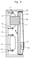
- FIG. 5 is a side view of a system with two separation chambers 6 shown.
- the drive of the permanent magnet used 2 takes place via an electric motor 51 and a drive gear 52, a chain hoist guided over pulleys 55 53 move along a running rail 54.
- the separation chambers 6 are firmly attached to a steel frame 8 via housing brackets 7. They are each with an inlet 10 and an outlet 11 Mistake.
- FIG. 6 shows an embodiment of the high gradient magnetic separator with a rotatable magnetic field source.
- a magnetic field source a permanent magnet 61 is used, which is perpendicular arranged shaft 62 in the middle of the permanent magnet 61 is rotatable.
- the permanent magnet 61 consists of two bar magnets 61a and 61b, both of which are mounted on the shaft 62 and which are rotated against each other by 180 °.
- the north and the The south pole of the bar magnets 61a and 61b are N and S, respectively designated.
- the shaft 62 is driven by the permanent magnet 61 by an electric motor 67.
Landscapes
- Centrifugal Separators (AREA)
Applications Claiming Priority (2)
| Application Number | Priority Date | Filing Date | Title |
|---|---|---|---|
| DE19753737 | 1997-12-04 | ||
| DE19753737 | 1997-12-04 |
Publications (1)
| Publication Number | Publication Date |
|---|---|
| EP0920916A1 true EP0920916A1 (fr) | 1999-06-09 |
Family
ID=7850678
Family Applications (1)
| Application Number | Title | Priority Date | Filing Date |
|---|---|---|---|
| EP98119959A Pending EP0920916A1 (fr) | 1997-12-04 | 1998-10-22 | Séparateur magnétique à gradient de champ fort |
Country Status (1)
| Country | Link |
|---|---|
| EP (1) | EP0920916A1 (fr) |
Cited By (3)
| Publication number | Priority date | Publication date | Assignee | Title |
|---|---|---|---|---|
| EP1127622A3 (fr) * | 2000-02-23 | 2002-07-10 | Outokumpu Oyj | Séparateur magnétique à faible intensité |
| DE102008035695A1 (de) | 2008-07-30 | 2010-02-04 | Martin Lipsdorf | Verfahren und Vorrichtung zur Bearbeitung von Partikeln gemäß ihrer magnetischen Suszeptibilität |
| CN111810814A (zh) * | 2020-07-17 | 2020-10-23 | 广东省大宝山矿业有限公司 | 一种磁选机放置架装置 |
Citations (3)
| Publication number | Priority date | Publication date | Assignee | Title |
|---|---|---|---|---|
| DE3312207A1 (de) * | 1983-04-05 | 1984-10-11 | Ukrainskij institut inženerov vodnogo chozjajstva, Rovno | Einrichtung zur absonderung ferromagnetischer werkstoffe aus fluessigen medien |
| FR2544224A1 (fr) * | 1983-04-18 | 1984-10-19 | Uk I Inzh | Separateur magnetique pour l'epuration de fluides contenant des particules ferromagnetiques |
| EP0347464A1 (fr) * | 1987-12-24 | 1989-12-27 | Ukrainsky Institut Inzhenerov Vodnogo Khozyaistva | Dispositif pour separer des substances ferromagnetiques contenues dans des milieux fluides |
-
1998
- 1998-10-22 EP EP98119959A patent/EP0920916A1/fr active Pending
Patent Citations (3)
| Publication number | Priority date | Publication date | Assignee | Title |
|---|---|---|---|---|
| DE3312207A1 (de) * | 1983-04-05 | 1984-10-11 | Ukrainskij institut inženerov vodnogo chozjajstva, Rovno | Einrichtung zur absonderung ferromagnetischer werkstoffe aus fluessigen medien |
| FR2544224A1 (fr) * | 1983-04-18 | 1984-10-19 | Uk I Inzh | Separateur magnetique pour l'epuration de fluides contenant des particules ferromagnetiques |
| EP0347464A1 (fr) * | 1987-12-24 | 1989-12-27 | Ukrainsky Institut Inzhenerov Vodnogo Khozyaistva | Dispositif pour separer des substances ferromagnetiques contenues dans des milieux fluides |
Cited By (3)
| Publication number | Priority date | Publication date | Assignee | Title |
|---|---|---|---|---|
| EP1127622A3 (fr) * | 2000-02-23 | 2002-07-10 | Outokumpu Oyj | Séparateur magnétique à faible intensité |
| DE102008035695A1 (de) | 2008-07-30 | 2010-02-04 | Martin Lipsdorf | Verfahren und Vorrichtung zur Bearbeitung von Partikeln gemäß ihrer magnetischen Suszeptibilität |
| CN111810814A (zh) * | 2020-07-17 | 2020-10-23 | 广东省大宝山矿业有限公司 | 一种磁选机放置架装置 |
Similar Documents
| Publication | Publication Date | Title |
|---|---|---|
| DE10354777A1 (de) | Elektromagnetisches Stellglied, Moduleinheit mit mehreren, nebeneinander angeordneten elektrischen Stellgliedern sowie Sortiereinrichtung zum Sortieren von unterschiedlichen, recycelbaren Stoffen | |
| DE4436045A1 (de) | Ausgleichselement | |
| DE102011014192B4 (de) | Elektromagnetische Aktuatorvorrichtung | |
| DE69817355T2 (de) | Stromabnehmer für ein elektrisches fahrzeug gespeist von einem selbst-isolierten stromleitung | |
| EP1725417B1 (fr) | Dispositif pour transmettre de l'energie electrique de la voie de circulation au vehicule d'un train a sustentation magnetique | |
| DE3117377A1 (de) | Verfahren und vorrichtung zum umwandeln einer antriebsbewegung | |
| DE19608844B4 (de) | Roboter | |
| WO2017153080A1 (fr) | Système de charge par induction pour véhicule, et utilisation | |
| DE29723852U1 (de) | Hochgradienten-Magnetseparator | |
| DE2903086A1 (de) | Elektromagnetische stelleinrichtung, insbesondere zum einstellen des stellarmes eines elektrohydraulischen servoventils | |
| DE69002108T2 (de) | Vorrichtung zum Bearbeiten plattenförmiger Werkstoffe. | |
| CH392909A (de) | Regelvorrichtung | |
| EP0086734B1 (fr) | Installation haute tension blindée à isolation gazeuse | |
| DE2331907A1 (de) | Automatische einstellvorrichtung in modulbauweise | |
| EP2944451B1 (fr) | Machine de formage thermique | |
| DE956130C (de) | Einrichtung zur Signalgebung durch magnetische Felder | |
| DE3827178C1 (en) | Apparatus for producing joining seams between overlapping film parts | |
| DE1563565A1 (de) | Elektrische Einstell- und/oder Stellungsanzeigevorrichtung | |
| EP2289154A2 (fr) | Agencement d'aimants permanents | |
| DE2425027A1 (de) | Magnetgefuehrtes und/oder -getragenes fahrzeug | |
| CH664645A5 (de) | Schaltvorrichtung zur steuerung von elektromotoren. | |
| DE2939540A1 (de) | Weiche fuer eine schwebebahn mit elektromagnetischer fuehrungseinrichtung | |
| DE202018000358U1 (de) | Stapelvorrichtung für Abdeckungsbaugruppen | |
| DE2202848C3 (de) | Vorrichtung zum Transportieren und Positionieren von Gegenständen, insbesondere Werkstücken | |
| DE102008031259B4 (de) | Drehvorrichtung und Verfahren zum Drehen eines Strahlführungsmagneten, sowie Strahlführungsmagnet |
Legal Events
| Date | Code | Title | Description |
|---|---|---|---|
| PUAI | Public reference made under article 153(3) epc to a published international application that has entered the european phase |
Free format text: ORIGINAL CODE: 0009012 |
|
| STAA | Information on the status of an ep patent application or granted ep patent |
Free format text: STATUS: THE APPLICATION HAS BEEN PUBLISHED |
|
| AK | Designated contracting states |
Kind code of ref document: A1 Designated state(s): AT BE CH CY DE DK ES FI FR GB GR IE IT LI LU MC NL PT SE |
|
| AX | Request for extension of the european patent |
Free format text: AL;LT;LV;MK;RO;SI |