EP0920924A2 - Dispositif d' élimination des déchets - Google Patents
Dispositif d' élimination des déchets Download PDFInfo
- Publication number
- EP0920924A2 EP0920924A2 EP98121901A EP98121901A EP0920924A2 EP 0920924 A2 EP0920924 A2 EP 0920924A2 EP 98121901 A EP98121901 A EP 98121901A EP 98121901 A EP98121901 A EP 98121901A EP 0920924 A2 EP0920924 A2 EP 0920924A2
- Authority
- EP
- European Patent Office
- Prior art keywords
- water
- garbage
- path
- section
- drainage
- Prior art date
- Legal status (The legal status is an assumption and is not a legal conclusion. Google has not performed a legal analysis and makes no representation as to the accuracy of the status listed.)
- Granted
Links
Images
Classifications
-
- F—MECHANICAL ENGINEERING; LIGHTING; HEATING; WEAPONS; BLASTING
- F26—DRYING
- F26B—DRYING SOLID MATERIALS OR OBJECTS BY REMOVING LIQUID THEREFROM
- F26B25/00—Details of general application not covered by group F26B21/00 or F26B23/00
- F26B25/005—Treatment of dryer exhaust gases
- F26B25/006—Separating volatiles, e.g. recovering solvents from dryer exhaust gases
-
- B—PERFORMING OPERATIONS; TRANSPORTING
- B09—DISPOSAL OF SOLID WASTE; RECLAMATION OF CONTAMINATED SOIL
- B09B—DISPOSAL OF SOLID WASTE NOT OTHERWISE PROVIDED FOR
- B09B3/00—Destroying solid waste or transforming solid waste into something useful or harmless
- B09B3/40—Destroying solid waste or transforming solid waste into something useful or harmless involving thermal treatment, e.g. evaporation
-
- Y—GENERAL TAGGING OF NEW TECHNOLOGICAL DEVELOPMENTS; GENERAL TAGGING OF CROSS-SECTIONAL TECHNOLOGIES SPANNING OVER SEVERAL SECTIONS OF THE IPC; TECHNICAL SUBJECTS COVERED BY FORMER USPC CROSS-REFERENCE ART COLLECTIONS [XRACs] AND DIGESTS
- Y02—TECHNOLOGIES OR APPLICATIONS FOR MITIGATION OR ADAPTATION AGAINST CLIMATE CHANGE
- Y02W—CLIMATE CHANGE MITIGATION TECHNOLOGIES RELATED TO WASTEWATER TREATMENT OR WASTE MANAGEMENT
- Y02W30/00—Technologies for solid waste management
- Y02W30/20—Waste processing or separation
Definitions
- the present invention relates to a garbage disposer for drying garbage.
- this garbage disposer by which garbage is dried so that it can be prevented from decaying and deodorized for the prevention of an offensive smell generated in the process of disposing the garbage.
- this garbage disposer is composed in such a manner that steam generated in the process of heating the garbage is deodorized and discharged outside.
- Garbage is mainly produced in the kitchen. Therefore, it is convenient to use a garbage disposer in the kitchen.
- various problems are caused and environment is deteriorated in the kitchen, for example, an offensive smell leaks and temperature in the kitchen is raised when steam is discharged from the garbage disposer, and further temperature in the kitchen is raised by the influence of a heat source incorporated into the garbage disposer. Therefore, it is difficult to arrange the garbage disposer in the kitchen.
- a garbage disposer comprising: a heating section for heating garbage; a condensing section for cooling and condensing steam generated from the garbage, communicated with the heating section; a drainage path for discharging water condensed in the condensing section to the outside; and an opening and closing means for opening and closing the drainage path, wherein the garbage is heated in the heating section so that water can be evaporated, and steam is condensed in the condensing section so that the garbage can be dried under the condition that the opening and closing means is closed and a space formed by the heating section and the condensing section, which are communicated with each other, is tightly closed.
- the present invention described in claim 2 provides a garbage disposer in which pretreatment is conducted on garbage before it is dried in such a manner that the garbage is heated and water is evaporated in the heating section under the condition that the opening and closing means is opened and air in the closed space is replaced with steam.
- garbage is heated in the heating section so that water can be evaporated, and steam is cooled and condensed in the condensing section so that the garbage can be dried under the condition that the opening and closing means is closed and a space formed by the heating section and the condensing section, which are communicated with each other, is tightly closed.
- Almost all of the offensive smell generated from the garbage is dissolved in condensed water. Therefore, when the opening and closing means is opened at a predetermined time and condensed water is discharged outside, for example, condensed water is discharged into a sewer pipe, the offensive smell component is discharged together with the condensed water. Accordingly, it is unnecessary to provide a deodorizing device. Further, since garbage is dried in a tightly closed space, it is possible to prevent a large quantity of steam from being discharged before the completion of condensation.
- pretreatment is conducted on garbage in such a manner that the garbage is heated in the heating section and water is evaporated under the condition that the opening and closing means is opened, so that steam is filled in the space and air is discharged.
- the opening and closing valve is closed and garbage is dried, steam is condensed in the condensing section under the condition that the space, in which the heating section and the condensing section are communicated with each other, is tightly closed. Due to the foregoing, the space, in which the heating section and the condensing section are communicated with each other, can be kept at a negative pressure. Accordingly, the leakage of an offensive smell can be prevented, and garbage can be dried at a low temperature because the boiling point is lowered. Therefore, it is possible to prevent wasting energy.
- pretreatment is not limited to a pretreatment conducted at the start of drying operation.
- pretreatment may be appropriately conducted when negative pressure is required even while drying operation is being conducted.
- a garbage disposer comprising:
- the present invention described in claim 4 provides a garbage disposer according to claim 3, wherein the shut-off drainage section has an S-shaped tube structure including: a downward path in which water flows downward from the condensing section; an upward path which rises upward from the downward path; and a drainage flow path in which water flows downward again, connected to the water drainage path.
- the present invention described in claim 5 provides a garbage disposer according to claim 3, the shut-off drainage section including: a tank for storing water; a condensed water drainage pipe in which water flows downward from the condensing section, the condensed water drainage pipe being arranged downward toward a bottom surface of the tank; and a drainage pipe for discharging water outside which exceeds a predetermined water level of the tank.
- a condensation pool for storing water is formed in a path from the condensing section to the drainage path.
- a path connecting the condensing section with the drainage path is shut off by the staying water in the condensation pool. Due to the foregoing, a communicating space in which the heating section and the condensing section are communicated with each other can be tightly closed. In this tightly closed space, garbage is heated and generated steam is condensed. Therefore, steam, which has not been condensed yet, is prevented from being discharged outside. Water condensed in the condensing section is sent to the condensation pool.
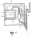
- Fig. 1 is a schematic arrangement view of a first embodiment of the garbage disposer of the present invention.
- This garbage disposer is incorporated into a system kitchen.
- the garbage disposer includes: a casing 10; a drawer 20 arranged in front of the casing 10; a processing tank 21 for accommodating garbage, fixed to the drawer 20; a heating chamber 30 forming a space for accommodating the processing tank 21; a heater 31 for heating the processing tank 21 in the heating chamber 30; a condensing chamber 40 for forming a space in which fin tube 41 and a tank 42 are accommodated; a fan 50 for sending air to the fin tube 41; a discharge pipe 60 for communicating the condensing chamber 40 with a drain pipe 1 connected with a sink; an opening and closing valve 61 for opening and closing a path of the discharge pipe 60; and a controller 70 for controlling the opening and closing valve 61 and for application voltage to a heater 31 and to a fan 50.
- the opening and closing valve 61 is closed in a normal condition. Therefore, it is possible to prevent an offensive smell from discharging from the drainage pipe 1.
- a clearance formed between the drawer 20 and the casing 10 is sealed. Therefore, when the opening and closing valve 61 is closed in the above condition, a space formed by the heating chamber 30 and the condensing chamber 40 is tightly closed. Walls forming the heating chamber 30 have a heat-insulating structure. Therefore, dew condensation of steam on the walls of the heating chamber 30 can be prevented.
- the heater 31, the fan 50 and the opening and closing valve 61 are controlled by the controller 70. In this way, the drying operation is carried out.
- the heating chamber 30 is continuously heated by the heater 31, however, when a quantity of heat taken from steam in the condensing chamber 40 is made to be larger than a quantity of heat given to steam in the heating chamber 30, it is possible to reduce the pressure in the tightly closed space.
- the condensing chamber 40 is kept at a negative pressure. Therefore, steam generated in the heating chamber 30 flows into the condensing chamber 40, and pressure in the heating chamber 30 also becomes negative, and the boiling point is lowered. Accordingly, it is possible to evaporate water even at a low temperature. Since pressure is kept negative in the tightly closed space, it is possible to prevent the offensive smell components from leaking outside.
- steam generated from heated garbage is condensed and discharged together with the offensive smell components. Due to the above arrangement, it is possible to prevent a leakage of the offensive smell components and also it is possible to prevent an increase in temperature. Therefore, the environment of the kitchen can be kept clean. Since pressure in the heating chamber 30 is kept negative, it is possible to prevent the leakage of the offensive smell components, and at the same time the boiling point is lowered, so that drying of garbage can be carried out at a low temperature. Due to the foregoing, energy required for heating can be reduced, that is, electric power consumption can be reduced, and at the same time the temperature in the kitchen can be prevented from rising.
- the heating chamber 30 is kept at a negative pressure, it is unnecessary to provide expensive devices such as a vacuum pump and others. Further, it is unnecessary to provide a deodorizing device and a steam discharging device. Accordingly, the structure can be made simple and the equipment cost can be reduced.
- the opening and closing valve 61 when the heating chamber 30 and the condensing chamber 40 are filled with steam, the opening and closing valve 61 is closed.
- the present invention is not limited to the above specific embodiment, for example, temperatures, humidities and pressures in the condensing chamber 40 and the heating chamber 30 are detected, and the time to close the opening and closing valve 61 may be determined by the result of the above detection, and also the time to close the opening and closing valve 61 may be determined by the lapse of time.
- the structure to heat the processing tank 21 is not limited to the heater 31, for example, the processing tank 21 may be heated by means of gas burners or micro waves.
- the opening and closing valve 61 is not limited to an electromagnetic valve, for example, it is possible to use a ball valve to be closed when a negative pressure is given to the valve.
- the cooling structure is not limited to the fan 50 which sends air for cooling steam.
- heat may be spontaneously radiated by utilizing a draft force.
- Condensed water may be discharged only after the completion of drying operation. Alternatively, condensed water may be discharged by a plurality of times in the process of operation. Before the opening and closing valve 61 is opened for discharging water, outside air may be sucked into the tightly closed space.
- the heating chamber 30 for heating garbage and the condensing chamber 40 for condensing steam are provided differently from each other. However, it should be noted that heating garbage and condensing steam may be conducted in the same chamber.
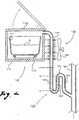
- Fig. 2 is a schematic arrangement view of the second embodiment of the garbage disposer of the present invention.
- This garbage disposer includes: a heating section for heating garbage; a condensing section 120 for condensing steam generated from garbage; and a shut-off drainage section 130 for shutting off a path communicating the condensing section 120 with the sewer pipe 101 and also for drainage.
- the heating section 110 includes: a processing tank 111 for accommodating garbage; a heater 112 for heating the processing tank 111; and a heating chamber 113 having a heat insulating structure for accommodating the processing tank 111 and the heater 112. In an upper portion of the heating chamber 113, there is provided a lid 113a to be opened and closed when the processing tank 111 is put into and taken out from the heating chamber 113.
- the condensing section 120 includes: a fin tube 121 communicating with an upper portion of the heating chamber 113; and a fan 122 for sending air to the fin tube 121.
- the shut-off drainage section 130 is composed of an S-shaped tube 131 including: a downward path 132 in which water sent from the fin tube 121 flows downward; an upward path 133 which rises upward from the downward path 132; and a drainage path 134 which is arranged downward from the upward path 133 and communicates with the sewer pipe 101.
- this garbage disposer When garbage is charged into the processing tank 111 and drying operation is started, the heater 112 starts heating the processing tank 111. Therefore, temperatures in the processing tank 111 and the heating chamber 113 are raised, and water contained in garbage is evaporated. Accordingly, air in the heating chamber 113 and the fin tube 121 is pushed into the sewer pipe 101 by steam generated from garbage. After a predetermined period of time has passed, the fan 122 is operated in the condensing section 120 and air is sent to the fin tube 121. Accordingly, steam in the fin tube 121 is cooled and condensed.
- a path in which gas flows from the downward path 132 to the upward path 133 is shut off. Accordingly, a space composed of the heating chamber 113 and the fin tube 121 can be tightly closed.
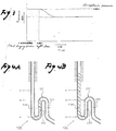
- pressure in the closed space is lowered as shown by the graph in Fig. 3. As a result, pressure in the heating chamber 113 becomes negative, and the boiling point is lowered.
- a quantity of water staying in the S-shaped tube 131 is increasing, however, when a water level of staying water in the upward path 133 exceeds the water level "b", water flows into the sewer pipe 101 via the drainage path 134. Accordingly, there is no possibility that staying water continues to increase. Therefore, the water level can be stabilized.
- a difference between the water level in the downward path 132 and the water level in the upward path 133 is determined by a difference between the pressure in the closed space and the pressure in the sewer pipe 101. Therefore, when the pressure in the closed space is kept negative, the water level in the downward pipe 132 is stabilized at the water level "c" which is higher than the water level "a". Almost all of the offensive smell components are dissolved in water staying in the S-shaped tube 131 and discharged into the sewer pipe 101.
- pressure in the closed pace is spontaneously adjusted. For example, when pressure in the closed space increases exceeding the atmospheric pressure, the water level in the downward path 132 is lowered. When the water level in the downward path 132 is lowered to the water level "a", gas in the downward path 132 is discharged into the upward path 133 as shown in Fig. 4A. For the above reasons, pressure in the closed space is increased only to a predetermined value determined by the difference between the water level in the upward path 133 and the water level in the downward path 132.
- the garbage disposer of the second embodiment when the path by which the downward path 132 is communicated with the upward path 133 is shut off by water staying in the S-shaped tube 131, it is possible to tightly close the communicating space composed of the heating chamber 113 and the fin tube 121 without using an opening and closing valve such as an electromagnetic valve. Therefore, the equipment cost can be reduced.
- water in the upward path 133 exceeds the water level "b"
- shut-off drainage section 130 can be composed of only the S-shaped pipe 131, the equipment cost can be reduced.
- steam generated from heated garbage is condensed and discharged together with the offensive smell components. Therefore, it is possible to prevent the offensive smell from leaking and to prevent the temperature from rising. Accordingly, the deterioration of the environment in the kitchen can be prevented. Since the heating chamber 113 is kept at a negative pressure, it is possible to prevent an offensive smell from leaking from a clearance between the lid 113a and the heating chamber 113. Therefore, it is unnecessary to provide an excessively high sealing property. Since the boiling point is lowered, drying of garbage can be conducted at low temperatures. Therefore, it is possible to reduce energy required for heating and also it is possible to reduce electric power consumption. As a result, it is possible to prevent the temperature in the kitchen from rising.
- the heating chamber 113 is kept at a negative pressure, it is unnecessary to provide expensive devices such as a vacuum pump. Further, it is unnecessary to provide a deodorizing device and a steam exhausting device. Therefore, the structure can be made simple and the equipment cost can be reduced.
- a quantity of water required for shutting off the communicating path may be reduced by making a lower space of the S-shaped tube 131 small. In this way, a period of time required for shutting off can be reduced.
- the communicating path may be shut off when water is staying in the communicating path at all times.
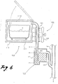
- Fig. 6 is a schematic arrangement view of the third embodiment of the garbage disposer of the present invention.
- the essential structure of the garbage disposer of the third embodiment is the same as that of the garbage disposer of the second embodiment shown in Fig. 2.
- the structure of the shut-off drainage section is different.
- Like reference characters are used to indicate like parts, and the explanations are omitted here.
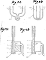
- the shut-off drainage section 140 includes: a tank 141 for storing water; a condensed water discharge pipe 142 in which water sent from the fin tube 121 flows downward, the condensed water discharge pipe 142 facing a bottom surface of the tank 141; and a drainage pipe 143 for discharging water, which has exceeded a predetermined water level "d" in the tank 141, into the sewer pipe 101, wherein the drainage pipe 143 communicates an upper side of the tank 141 with the sewer pipe 101.
- a path communicating the condensed water discharge pipe 142 with the drainage pipe 143 is shut off when the water level of water staying in the tank 141 is increased higher than the lower end opening surface (the water level "f") of the condensed water discharge pipe 142.
- the water level "f" the lower end opening surface of the condensed water discharge pipe 142.
- the pressure in the closed space is increased to a value higher than the atmospheric pressure, the water level in the condensed water discharge pipe 142 is decreased.
- the water level in the condensed water discharge pipe 142 is decreased to the water level "f"
- air in the condensed water discharge pipe 142 is discharged into the tank 141 as shown in Fig. 7A. Consequently, the pressure in the closed space is increased only to a predetermined value determined by the difference between the water level in the tank 141 and the water level in the condensed water discharge pipe 142.
- the pressure in the closed space is decreased to a value lower than the atmospheric pressure, the water level in the condensed water discharge pipe 142 is increased, and the water level in the tank 141 is decreased.
- the water level in the tank 141 is decreased to the water level "f"
- air is sucked from the tank 141 into the condensed water discharge pipe 142 as shown in Fig. 7B. Consequently, the pressure in the closed space is decreased only to a predetermined value determined by the difference between the water level in the condensed water discharge pipe 142 and the water level in the tank 141. That is, the pressure in the closed space can be spontaneously adjusted and kept at an appropriate value.
- the following effect can be provided in addition to the effect provided by the second embodiment.
- the shut-off condition can be kept until the water level in the tank 141 is decreased to the water level "f". Accordingly, when height of the condensed water discharge pipe 142 in the perpendicular direction of the heating chamber 113 is increased and a capacity of the tank 141 is increased, it is possible to set a limit value of the negative pressure irrespective of a limit value of the positive pressure. Accordingly, when the limit value of the positive pressure is decreased and the limit value of the negative pressure is increased, it is possible to keep the pressure in the closed space negative.
- the fan 122 is operated after a predetermined period of time has passed from the heating by the heater 112.
- the present invention is not limited to the above specific embodiment.
- the temperature, humidity, or pressure in the fin tube 121 or the heating chamber 113 are detected, and the fan 122 may be operated in accordance with the detection values.
- the heater 112 may be simultaneously operated.
- the heating means for heating garbage is not limited to the heater 112.
- a heating means such as a gas burner or micro waves.
- the cooling means for cooling the condensing section 120 is not limited to the fan 122.
- the condensing section 120 may be spontaneously cooled by utilizing a draft force.
- the heating chamber 110 and the condensing section 120 are provided differently from each other. However, it is possible to adopt an arrangement in which heating and condensing are conducted in the same chamber.
- the garbage disposer described in claim 1 of the present invention while garbage is being heated in the tightly closed space, generated steam is condensed. Due to the above arrangement, it is possible to prevent steam being discharged without being condensed. Further, almost all of the offensive smell components are dissolved in the condensed water. Therefore, for example, when the condensed water is discharged into a sewer pipe, it is possible to prevent a leakage of the offensive smell components, and also it is possible to prevent an increase in the humidity, that is, it is possible to prevent the deterioration of the environment in the kitchen. Further, it is unnecessary to provide a deodorizing device and a steam discharging device. Accordingly, the structure can be made simple and the equipment cost can be reduced.
- the garbage disposer described in claim 2 of the present invention when pressure in the heating section is kept negative, it is possible to prevent the leakage of the offensive smell components. The boiling point is lowered, so that drying of garbage can be carried out at a low temperature. Due to the above structure, energy required for heating can be reduced, and at the same time the temperature in the kitchen can be prevented from rising. Since the heating section is kept at a negative pressure, it is unnecessary to provide expensive devices such as a vacuum pump and others. Accordingly, the structure can be made simple and the equipment cost can be reduced.
- the path, in which the condensing section and the drainage path are communicated with each other, is shut off by water staying in the condensed water pool. Therefore, the communicating path between the heating section and the condensing section can be tightly closed without using an opening and closing valve such as an electromagnetic valve. Accordingly, the equipment cost can be reduced.
- water staying in the condensed water pool exceeds a predetermined discharging water level, it is discharged to the outside such as a sewer pipe. Therefore, while the tightly closed condition is being kept, water can be discharged outside.
- the shut-off drainage section can be composed of one tube. Therefore, the structure is simple and the equipment cost can be reduced.
- the negative pressure limit of the closed space when the tank capacity is increased, the negative pressure limit of the closed space can be set at a high value irrespective of the positive pressure limit. Accordingly, it is easy to keep the closed space at a negative pressure.
Landscapes
- Engineering & Computer Science (AREA)
- Mechanical Engineering (AREA)
- General Engineering & Computer Science (AREA)
- Physics & Mathematics (AREA)
- Thermal Sciences (AREA)
- Environmental & Geological Engineering (AREA)
- Processing Of Solid Wastes (AREA)
- Drying Of Solid Materials (AREA)
Applications Claiming Priority (4)
| Application Number | Priority Date | Filing Date | Title |
|---|---|---|---|
| JP33631197A JP3739069B2 (ja) | 1997-11-19 | 1997-11-19 | 厨芥処理機 |
| JP33631197 | 1997-11-19 | ||
| JP9361804A JPH11169817A (ja) | 1997-12-09 | 1997-12-09 | 厨芥処理機 |
| JP36180497 | 1997-12-09 |
Publications (3)
| Publication Number | Publication Date |
|---|---|
| EP0920924A2 true EP0920924A2 (fr) | 1999-06-09 |
| EP0920924A3 EP0920924A3 (fr) | 2001-07-04 |
| EP0920924B1 EP0920924B1 (fr) | 2003-06-25 |
Family
ID=26575430
Family Applications (1)
| Application Number | Title | Priority Date | Filing Date |
|---|---|---|---|
| EP98121901A Expired - Lifetime EP0920924B1 (fr) | 1997-11-19 | 1998-11-18 | Dispositif d' élimination des déchets |
Country Status (7)
| Country | Link |
|---|---|
| US (1) | US6012233A (fr) |
| EP (1) | EP0920924B1 (fr) |
| KR (1) | KR100495641B1 (fr) |
| CN (1) | CN1108263C (fr) |
| DE (1) | DE69815797T2 (fr) |
| ES (1) | ES2201395T3 (fr) |
| TW (1) | TW553036U (fr) |
Cited By (1)
| Publication number | Priority date | Publication date | Assignee | Title |
|---|---|---|---|---|
| CN108728350A (zh) * | 2018-07-20 | 2018-11-02 | 杭州洁洁环保科技有限公司 | 负压恒温干燥设备 |
Families Citing this family (9)
| Publication number | Priority date | Publication date | Assignee | Title |
|---|---|---|---|---|
| KR100781110B1 (ko) * | 2005-06-02 | 2007-11-30 | 방정자 | 악취가 발생하지 않는 음식물 쓰레기 건조기 |
| KR100747047B1 (ko) * | 2006-05-02 | 2007-08-10 | 주식회사 두림코리아 | 음식물 쓰레기 처리장치 |
| KR100980297B1 (ko) | 2008-03-28 | 2010-09-06 | 김남주 | 음식물 쓰레기 처리시스템 및 처리방법 |
| KR101060314B1 (ko) | 2009-02-18 | 2011-08-30 | (주)씨에스아이엔씨 | 마이크로파 가열수단과 온풍 가열수단을 겸하여 수용하는 음식물쓰레기 처리장치 및 그 제어방법 |
| KR101251131B1 (ko) * | 2010-05-12 | 2013-04-04 | 코웨이 주식회사 | 음식물 처리기 건조로 어셈블리의 작동 종료 제어 방법 |
| CN108543806A (zh) * | 2018-05-18 | 2018-09-18 | 黄昱帆 | 一种餐厨有机垃圾处理机 |
| KR102276946B1 (ko) * | 2019-12-27 | 2021-07-13 | (주)지에이 | 음식 폐기물 처리 장치 |
| CN112009908B (zh) * | 2020-07-30 | 2022-05-13 | 福州美佳环保资源开发有限公司 | 一种垃圾分类用多功能收集装置 |
| CN112229155B (zh) * | 2020-09-28 | 2022-05-31 | 南昌航天文化科技有限公司 | 一种纳米清洁丙烯画颜料生产设备 |
Family Cites Families (11)
| Publication number | Priority date | Publication date | Assignee | Title |
|---|---|---|---|---|
| US5174042A (en) * | 1990-08-20 | 1992-12-29 | Matsushita Electric Industrial Co., Ltd. | Garbage disposer utilizing microwave heating |
| JPH04193382A (ja) * | 1990-11-27 | 1992-07-13 | Matsushita Electric Ind Co Ltd | ごみ処理装置 |
| JPH0531476A (ja) * | 1991-07-29 | 1993-02-09 | Matsushita Electric Ind Co Ltd | ごみ処理装置 |
| JP2692463B2 (ja) * | 1991-11-27 | 1997-12-17 | 松下電器産業株式会社 | 生ごみ処理処理機 |
| JPH05275170A (ja) * | 1991-12-12 | 1993-10-22 | Matsushita Electric Ind Co Ltd | 乾燥処理装置 |
| JP3149498B2 (ja) * | 1992-01-16 | 2001-03-26 | 松下電器産業株式会社 | 厨芥処理機 |
| JP2514050Y2 (ja) * | 1992-01-30 | 1996-10-16 | テクノエクセル株式会社 | 浄水槽 |
| JPH0563686U (ja) * | 1992-02-03 | 1993-08-24 | 株式会社太庸機械製作所 | 生ごみ処理装置 |
| JPH06312801A (ja) * | 1993-04-30 | 1994-11-08 | Sanyo Electric Co Ltd | 生ごみ処理装置 |
| JPH0814750A (ja) * | 1994-07-04 | 1996-01-19 | Sharp Corp | 生ゴミ処理装置 |
| KR0118079Y1 (ko) * | 1994-09-30 | 1998-04-24 | 김광호 | 음식쓰레기 처리기 |
-
1998
- 1998-11-12 US US09/189,974 patent/US6012233A/en not_active Expired - Fee Related
- 1998-11-18 DE DE69815797T patent/DE69815797T2/de not_active Expired - Lifetime
- 1998-11-18 ES ES98121901T patent/ES2201395T3/es not_active Expired - Lifetime
- 1998-11-18 EP EP98121901A patent/EP0920924B1/fr not_active Expired - Lifetime
- 1998-11-19 TW TW092202748U patent/TW553036U/zh not_active IP Right Cessation
- 1998-11-19 CN CN98122511A patent/CN1108263C/zh not_active Expired - Fee Related
- 1998-11-19 KR KR10-1998-0049827A patent/KR100495641B1/ko not_active Expired - Fee Related
Cited By (1)
| Publication number | Priority date | Publication date | Assignee | Title |
|---|---|---|---|---|
| CN108728350A (zh) * | 2018-07-20 | 2018-11-02 | 杭州洁洁环保科技有限公司 | 负压恒温干燥设备 |
Also Published As
| Publication number | Publication date |
|---|---|
| DE69815797T2 (de) | 2004-02-12 |
| ES2201395T3 (es) | 2004-03-16 |
| KR100495641B1 (ko) | 2005-09-16 |
| DE69815797D1 (de) | 2003-07-31 |
| EP0920924B1 (fr) | 2003-06-25 |
| HK1019220A1 (en) | 2000-01-28 |
| CN1217280A (zh) | 1999-05-26 |
| TW553036U (en) | 2003-09-11 |
| US6012233A (en) | 2000-01-11 |
| EP0920924A3 (fr) | 2001-07-04 |
| KR19990045429A (ko) | 1999-06-25 |
| CN1108263C (zh) | 2003-05-14 |
Similar Documents
| Publication | Publication Date | Title |
|---|---|---|
| US6012233A (en) | Garbage disposer | |
| CN1283199C (zh) | 过热蒸汽炉 | |
| US6076271A (en) | Garbage disposer | |
| JP2004116846A (ja) | 乾燥システム | |
| KR100942453B1 (ko) | 음식물쓰레기 처리장치 | |
| KR101730001B1 (ko) | 압력상승방지 버퍼 유닛을 구비한 음식물처리기 | |
| US5573182A (en) | Heat pump hot water heater | |
| WO2007145426A1 (fr) | Appareil de séchage pour déchets ALIMENTAIRES | |
| JP3612120B2 (ja) | 真空乾燥装置 | |
| JPH10103861A (ja) | 水蒸気再圧縮式真空乾燥装置 | |
| JP3739069B2 (ja) | 厨芥処理機 | |
| JP4375762B2 (ja) | 厨芥処理機 | |
| JP2000189926A (ja) | 厨芥処理機 | |
| RU2121627C1 (ru) | Замкнутая автономная система отопления | |
| JPH11169817A (ja) | 厨芥処理機 | |
| JP3767584B2 (ja) | 蒸気発生機能付き高周波加熱装置 | |
| JP2000000543A (ja) | 厨芥処理器 | |
| JP3777769B2 (ja) | 厨芥処理機 | |
| JP2004074013A (ja) | 厨芥処理機 | |
| JP3568262B2 (ja) | 生ごみ処理装置 | |
| JP2001108367A (ja) | 厨芥処理機 | |
| JPH11169821A (ja) | 厨芥処理機 | |
| JPH11179326A (ja) | 厨芥処理機 | |
| JPH10253081A (ja) | 循環加熱装置 | |
| JP2000051812A (ja) | 厨芥処理機 |
Legal Events
| Date | Code | Title | Description |
|---|---|---|---|
| PUAI | Public reference made under article 153(3) epc to a published international application that has entered the european phase |
Free format text: ORIGINAL CODE: 0009012 |
|
| AK | Designated contracting states |
Kind code of ref document: A2 Designated state(s): DE ES FR GB IT |
|
| AX | Request for extension of the european patent |
Free format text: AL;LT;LV;MK;RO;SI |
|
| PUAL | Search report despatched |
Free format text: ORIGINAL CODE: 0009013 |
|
| AK | Designated contracting states |
Kind code of ref document: A3 Designated state(s): AT BE CH CY DE DK ES FI FR GB GR IE IT LI LU MC NL PT SE |
|
| AX | Request for extension of the european patent |
Free format text: AL;LT;LV;MK;RO;SI |
|
| 17P | Request for examination filed |
Effective date: 20011010 |
|
| AKX | Designation fees paid |
Free format text: DE ES FR GB IT |
|
| 17Q | First examination report despatched |
Effective date: 20020704 |
|
| GRAH | Despatch of communication of intention to grant a patent |
Free format text: ORIGINAL CODE: EPIDOS IGRA |
|
| GRAH | Despatch of communication of intention to grant a patent |
Free format text: ORIGINAL CODE: EPIDOS IGRA |
|
| GRAA | (expected) grant |
Free format text: ORIGINAL CODE: 0009210 |
|
| AK | Designated contracting states |
Designated state(s): DE ES FR GB IT |
|
| REG | Reference to a national code |
Ref country code: GB Ref legal event code: FG4D |
|
| REF | Corresponds to: |
Ref document number: 69815797 Country of ref document: DE Date of ref document: 20030731 Kind code of ref document: P |
|
| REG | Reference to a national code |
Ref country code: ES Ref legal event code: FG2A Ref document number: 2201395 Country of ref document: ES Kind code of ref document: T3 |
|
| ET | Fr: translation filed | ||
| PLBE | No opposition filed within time limit |
Free format text: ORIGINAL CODE: 0009261 |
|
| STAA | Information on the status of an ep patent application or granted ep patent |
Free format text: STATUS: NO OPPOSITION FILED WITHIN TIME LIMIT |
|
| 26N | No opposition filed |
Effective date: 20040326 |
|
| PGFP | Annual fee paid to national office [announced via postgrant information from national office to epo] |
Ref country code: ES Payment date: 20091125 Year of fee payment: 12 Ref country code: DE Payment date: 20091112 Year of fee payment: 12 |
|
| PGFP | Annual fee paid to national office [announced via postgrant information from national office to epo] |
Ref country code: IT Payment date: 20091116 Year of fee payment: 12 Ref country code: GB Payment date: 20091118 Year of fee payment: 12 Ref country code: FR Payment date: 20091123 Year of fee payment: 12 |
|
| GBPC | Gb: european patent ceased through non-payment of renewal fee |
Effective date: 20101118 |
|
| REG | Reference to a national code |
Ref country code: FR Ref legal event code: ST Effective date: 20110801 |
|
| REG | Reference to a national code |
Ref country code: DE Ref legal event code: R119 Ref document number: 69815797 Country of ref document: DE Effective date: 20110601 Ref country code: DE Ref legal event code: R119 Ref document number: 69815797 Country of ref document: DE Effective date: 20110531 |
|
| PG25 | Lapsed in a contracting state [announced via postgrant information from national office to epo] |
Ref country code: DE Free format text: LAPSE BECAUSE OF NON-PAYMENT OF DUE FEES Effective date: 20110531 |
|
| PG25 | Lapsed in a contracting state [announced via postgrant information from national office to epo] |
Ref country code: FR Free format text: LAPSE BECAUSE OF NON-PAYMENT OF DUE FEES Effective date: 20101130 |
|
| PG25 | Lapsed in a contracting state [announced via postgrant information from national office to epo] |
Ref country code: GB Free format text: LAPSE BECAUSE OF NON-PAYMENT OF DUE FEES Effective date: 20101118 |
|
| PG25 | Lapsed in a contracting state [announced via postgrant information from national office to epo] |
Ref country code: IT Free format text: LAPSE BECAUSE OF NON-PAYMENT OF DUE FEES Effective date: 20101118 |
|
| REG | Reference to a national code |
Ref country code: ES Ref legal event code: FD2A Effective date: 20120110 |
|
| PG25 | Lapsed in a contracting state [announced via postgrant information from national office to epo] |
Ref country code: ES Free format text: LAPSE BECAUSE OF NON-PAYMENT OF DUE FEES Effective date: 20101119 |