EP0920953B1 - Verfahren und Vorrichtung zur Messung einer mechanischen Verformung der Füsse von mindestens einer Maschine - Google Patents
Verfahren und Vorrichtung zur Messung einer mechanischen Verformung der Füsse von mindestens einer Maschine Download PDFInfo
- Publication number
- EP0920953B1 EP0920953B1 EP98116513A EP98116513A EP0920953B1 EP 0920953 B1 EP0920953 B1 EP 0920953B1 EP 98116513 A EP98116513 A EP 98116513A EP 98116513 A EP98116513 A EP 98116513A EP 0920953 B1 EP0920953 B1 EP 0920953B1
- Authority
- EP
- European Patent Office
- Prior art keywords
- soft
- foot
- soft foot
- machines
- condition
- Prior art date
- Legal status (The legal status is an assumption and is not a legal conclusion. Google has not performed a legal analysis and makes no representation as to the accuracy of the status listed.)
- Expired - Lifetime
Links
- 238000000034 method Methods 0.000 title claims abstract description 27
- 238000005259 measurement Methods 0.000 claims abstract description 14
- 230000009471 action Effects 0.000 claims abstract description 12
- 238000012360 testing method Methods 0.000 description 15
- 230000008569 process Effects 0.000 description 9
- 230000000694 effects Effects 0.000 description 6
- 230000003213 activating effect Effects 0.000 description 5
- 230000008878 coupling Effects 0.000 description 4
- 238000010168 coupling process Methods 0.000 description 4
- 238000005859 coupling reaction Methods 0.000 description 4
- 230000011664 signaling Effects 0.000 description 4
- 238000004458 analytical method Methods 0.000 description 3
- 238000011156 evaluation Methods 0.000 description 3
- 238000011835 investigation Methods 0.000 description 3
- 230000002411 adverse Effects 0.000 description 2
- 230000007547 defect Effects 0.000 description 2
- 238000007689 inspection Methods 0.000 description 2
- 238000012546 transfer Methods 0.000 description 2
- 230000008901 benefit Effects 0.000 description 1
- 238000002485 combustion reaction Methods 0.000 description 1
- 238000010276 construction Methods 0.000 description 1
- 238000012937 correction Methods 0.000 description 1
- 238000001514 detection method Methods 0.000 description 1
- 238000003745 diagnosis Methods 0.000 description 1
- 238000009434 installation Methods 0.000 description 1
- 238000012423 maintenance Methods 0.000 description 1
- 238000012986 modification Methods 0.000 description 1
- 230000004048 modification Effects 0.000 description 1
- 230000000153 supplemental effect Effects 0.000 description 1
- 230000009897 systematic effect Effects 0.000 description 1
Images


Classifications
-
- B—PERFORMING OPERATIONS; TRANSPORTING
- B23—MACHINE TOOLS; METAL-WORKING NOT OTHERWISE PROVIDED FOR
- B23Q—DETAILS, COMPONENTS, OR ACCESSORIES FOR MACHINE TOOLS, e.g. ARRANGEMENTS FOR COPYING OR CONTROLLING; MACHINE TOOLS IN GENERAL CHARACTERISED BY THE CONSTRUCTION OF PARTICULAR DETAILS OR COMPONENTS; COMBINATIONS OR ASSOCIATIONS OF METAL-WORKING MACHINES, NOT DIRECTED TO A PARTICULAR RESULT
- B23Q1/00—Members which are comprised in the general build-up of a form of machine, particularly relatively large fixed members
- B23Q1/01—Frames, beds, pillars or like members; Arrangement of ways
-
- B—PERFORMING OPERATIONS; TRANSPORTING
- B23—MACHINE TOOLS; METAL-WORKING NOT OTHERWISE PROVIDED FOR
- B23Q—DETAILS, COMPONENTS, OR ACCESSORIES FOR MACHINE TOOLS, e.g. ARRANGEMENTS FOR COPYING OR CONTROLLING; MACHINE TOOLS IN GENERAL CHARACTERISED BY THE CONSTRUCTION OF PARTICULAR DETAILS OR COMPONENTS; COMBINATIONS OR ASSOCIATIONS OF METAL-WORKING MACHINES, NOT DIRECTED TO A PARTICULAR RESULT
- B23Q17/00—Arrangements for observing, indicating or measuring on machine tools
Definitions
- the present invention relates to a method and apparatus for detecting a soft foot condition of one or more machines.
- soft foot as used throughout this text, relates to the usage as is common among engineers, technicians etc., and is not directly related to the usage of the same term, as used in the medical or related arts. For those persons not acquainted with this term it should be explained that normally nothing is “soft” with the feet under inspection. To the contrary, the feet are quite inelastic. However, once the feet tie a machine under test to the ground in a sturdy fashion, then the geometric constraints of the feet and/or shop floor ground will cause small, but intolerable mechanical deformation or distortion of such specific machine.
- the invention is based on the principles and the measurement capabilities of a laser alignment instrument, but is not limited to using an instrument of this specific type.
- Measuring equipment of the laser alignment type is already able to generally indicate a soft foot condition on a machine train.
- the Optalign and the Rotalign systems of German manufacturer Pruftechnik are able to carry out such measurements.
- only numeric values informing about the magnitude of a soft foot condition are indicated, without providing any information on how to resolve such condition.
- Such advice will be systematically derived by a computer and will relate to remedies considered to be most effective or important, and will be provided to the operator of such instrument either by a readout (i.e. alphanumeric information or pictograms) on a screen or a display of an instrument employed for this purpose.
- a readout i.e. alphanumeric information or pictograms
- such instrument will have an acoustical output, i.e. will provide information in a common language.
- acoustical output it may be of additional benefit to also have an acoustic input, employing direct speech input via a microphone to a computer, in order to implement an additional channel of inputting information or commands to such instrument. It is preferred, to have such instruments be of the portable type.
- a soft foot condition will be carried out on a machine to be tested. This is done in a manner as already known - e.g. loosening screws or nuts that normally clamp down the feet of the machine to the shop floor. One after another of such nuts or screws will be loosened on the machine under test, and the relating deviation of the contacting surface of a specific foot in relation to an ideal plane, if any, will be indicated as a numerical value and registered in a memory of the device of the present invention.
- the instrument will proceed according to the method of analysis of the invention to finally suggest the most feasible corrective action, or give ranked information on such useful actions, in case several seem appropriate. As indicated above, such suggestion can be presented to the user of the device via a display, a screen, an acoustical output, singly or in combination.
- FIG. 1A As shown in Fig. 1A, several mechanical defects are known that will cause a soft foot condition.
- a piece of rotating equipment 11, such as a machine tool or the like, may be fastened by its four feet to a shop floor 10.
- a parallel air gap is present under foot 13.
- a parallel air gap is present under the inclined bottom surface of bent foot 15. Clamping down foot 15 to the ground 10 will give rise to a soft foot condition with a distorted machine housing or casing as well.
- FIG. 1C Another situation of similar kind is depicted in Fig. 1C, indicating what is also called a “squishy foot” condition, which is caused by shims 18 of inadequate quality, or foreign matter between foot 17 and the floor or ground 10.
- Fig. 1D A further situation of a similar kind is depicted in Fig. 1D, indicating what is called an "induced soft foot” condition, which is attributable to a distortion of the machine housing 11 induced by an external load or force, which, for example, may be induced via a coupling flange 19 that is used to connect two (misaligned) shafts.
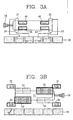
- Fig. 2 shows a top view of a piece of machinery with a rotatable shaft, spindle or the like.
- reference numerals 21-24 are shown, above or below which are indicated calculated soft foot values.
- Such calculations of soft foot values are obtained by first obtaining alignment values of a machine train with all its basic fastening elements strapped down to the shop floor, then loosening such fastening elements singly and one after another, in an ordered fashion, and taking alignment measurements on the machine in a regular procedure.
- additional numerical values are shown that represent the values of clearances, measured manually with a feeler gage, with the basic fastening element of that specific machine foot loosened.
- the apparatus according to the invention may comprise softkeys 30 for inputting or editing clearances that are observed under specific feet, as symbolized by reference numerals 21-24, on a symbolized machine, the direction of which is symbolized by an indication of a coupling flange 19. It is possible to enter several values for each foot, that relate to measured clearances under a specific foot of a machine in case the related fastening element has been completely loosened or removed. Reference numerals 41-43 indicate input fields for such measured values, that are on the inboard side of the machine. By activating one of the softkeys 30 it is possible to select input fields for entering measured values on the outboard side of each single foot.
- the device in a first step in accordance with the method of the present invention will display values as entered in fields 51-54, as well as calculated values indicating the magnitude of the soft foot condition for each foot of the machine, as depicted in fields 31-34.
- Softkey-line 40 is available for entering further commands or for performing further editing.
- One of the most important commands as mentioned above will be the systematic evaluation of such numerical values displayed on the display and simultaneously present in the memory of the device according to the invention, in order to perform a machine assisted evaluation on the most likely underlying cause of a noticed soft foot condition.
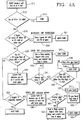
- a conventional measurement with subsequent calculation of soft foot condition is performed on all four feet of a machine under test, preferably using a laser based aligning instrument.
- the calculated values of the soft foot condition will be kept in the memory of the device.
- Step s11 being completed, the next step to be performed is S12, in which the results of step S11 will be evaluated. If all soft foot conditions are calculated to be less than 2/1000 of an inch (2.0 mils), the procedure will branch to step S13. With all values within predefined limits, there is no soft foot condition to correct, and after signaling such information to the operator by means of the display of the device according to the invention, the routine may terminate, preferably after having logged all relevant data in the memory of the device or in a host computer optionally connected by signal transmitting means to such device. It is also possible to employ acoustical signaling means to indicate that no further actions are necessary.
- step S19 it is decided whether or not the three largest calculated soft feet conditions are of comparable magnitude, i.e. do not exceed an upper or lower boundary relative to their mean value (arithmetic mean, for example), which boundary will not differ by more than 5% of that mean value, or by more than 5/10000 of an inch (0.5 mils) absolute value compared to that mean value.
- mean value arithmetic mean, for example
- step S20 will be performed, in which a message is forwarded to the operator to loosen all bolts or primary fasteners on the machine under test and fill all visible gaps under the feet of the machine, maybe additionally checking on the local sturdiness of the floor.
- Step S20 generally relates to the condition, or activity, that is called rough soft foot. This is a millwright procedure by which the machine base bolts are loosened, and efforts are carried out to have each foot of the machine support the same load, or the correct proportion of the load, as well as to have each foot in full co-planar contact with its shim pad, i.e. with even loading over the area under each foot.
- Step S20 being completed, the process will continue with step S21 and prompt the operator to return to step S11 (start) or will automatically do so by itself, so that the soft foot evaluation on all four feet can be carried out again.
- step S30 will be performed, in which it is determined whether or not at least one soft foot condition has been calculated to be 2% larger than all others and, in an absolute value, simultaneously be 5/10000 of an inch (0.5 mils) larger than all others calculated. It will again be appreciated, that it is advantageous to have such task carried out by a computer, rather than manually. If a positive determination is made in step S30, i.e. the "larger" condition was determined, the process will branch to perform step S40. In this step the operator will be notified to loosen a specific foot, according to what has been calculated by the instrument, and to measure the dimension of the gap below that foot, at all four corners of the foot.
- step S41 After all required values for a specific single gap have been entered into the device, step S41 will be performed. In step S41 the device will decide, based upon a prior calculation performed by the device, whether or not the average measured gap value has been determined to be greater than 70 % of the formerly calculated, numerical value of the soft foot condition. Upon this decision, either step S42 or S45 will be carried out automatically. Step S42 relates to the negative outcome, if the average gap value is greater than 70% of the calculated soft foot condition.
- the operator will be messaged, either acoustically or optically, that the foot currently under inspection is likely to be of the "squishy" type, possibly caused by foreign matter under the foot, or other circumstances that offer a higher mechanical compliance to the foot than intended or specified.
- a message may be displayed, in addition, to inspect a shim pack, if already present under the foot, and to clean it, if necessary, while taking care not to employ more than three shims simultaneously.
- step S45 numerical calculations and logical decisions are carried out to determine whether the following conditions are simultaneously true: a) if the maximal extension of a single gap is still smaller than 1.2 times the smallest extension determined under that specific foot, and b) if the difference between the extensions, represented by the term "max gap - min gap", is less than or equal to 4/1000 of an inch (4 mils, equivalent to about 0.1 millimeter, or 100 microns). If both conditions are true, the process will continue with step S47, signaling (or messaging) that the found gap requires filling, which should be done in a manner preferred in the art, i.e.
- step S46 also signaling to eliminate the gap found, but by step shimming, as is also an accepted method in the art.
- step S48 shimming with swivel-shims according to the Lysen invention (German application No. ____, U.S. application No. ______, to be distributed by Ludeca, Inc. of Miami), may be considered.
- step S48 which is a branch to step S 11, in order to be ready for performing another machine assisted investigation of a soft foot condition.
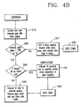
- step S50 will be performed. In this step, it is determined whether the two largest calculated soft foot predictions are diagonally opposite on the machine under test. If it is determined that they are diagonally opposite, the procedure will continue with step S60.
- This step relates to the situation where two calculated, or predicted, soft foot conditions are about the same size.
- the operator will be prompted to loosen both fastening elements (e.g. nuts) for the specific feet being tested.
- the operator will also be prompted to measure the specific dimensions of the gaps below those two feet, preferably at all four corners of each foot. The operator may do so using a feeler gage, or an instrument that will provide its readings in machine readable form, i.e.
- step S61 in order to perform calculations and determine whether the average gage value (for each foot measured) amounts to more than 70% of the predicted value of the soft foot condition. If the outcome of such investigation, as applied to a single foot of the two mentioned, is in the positive, then the process will continue with step S62, where the operator will be prompted to fill the gap found, or step shim such gap, if necessary, employing accepted methods of the art.
- step S63 by which the operator is informed that a specific foot (of the two feet currently under test) is likely to be "squishy.” The operator will also be informed or prompted to do the following: to inspect a shim pack, possibly present under such foot, to clean the gap and/or shim pack, and reinstall a shim pack, preferably an unused one, with less than four shims.
- step S62 or S63 the routine will branch via step S64 to step S11, so that a new measurement on a soft foot condition may be carried out.
- step S70 the routine according to the inventive method branches to step S70.
- This branch relates to the condition that the two largest predicted soft foot conditions are predicted to be found either on the inboard side, the outboard side, or one of the sidelines of the machine under test.
- step S70 the operator will therefore be prompted to loosen the mentioned two feet that are predicted to exhibit the largest soft foot conditions.
- the operator will also be prompted to measure the gaps of such feet to be tested, in a similar fashion as has been set out above.
- step S80 will be encountered, in which a calculation and decision is performed very similar to that of step S61.
- step S81 the routine will branch to step S81, prompting the operator in the same way as in step S63.
- step S63 the routine will commence via step S82 to S11, so that a new standard prediction on a soft foot condition may be carried out, in order to check for any remaining corrective action.
- step S90 it will be decided in accordance with the present invention in step S90 if the two largest soft foot conditions are predicted to be on either end of the machine (ends of the machine relating to the ends of the main shaft of such a machine). If the answer is in the positive, the routine will branch to step S91, where it is signaled to the operator that the observed soft foot condition may be due to an induced effect.
- induced effect may relate to the fact that a coupling strain is possibly present, which may be confirmed by opening the coupling on the shaft of the machine under test, or by checking the alignment of the machine under test with regard to its counterpart.
- step S92 of the routine will be encountered. This step will display a message to the operator that the induced soft foot condition is very likely due to external strains. Therefore, the operator (for example, a millwright), may also receive a message to remove possible pipe strains and any other side loads that may be present on the machine under test.
- step S93 which will branch to step S11 for entering a renewed, possibly final check on a soft foot condition on the machine under test.
- FIG. 5A An illustration of a displayed message and a softkey-menu 60 to choose from is depicted in Fig. 5A, which relates to Step S20.
- a text message 62 in plain language is displayed, which may be accompanied by an appropriate "grouchy" icon 62 (instead of a "smiley” icon).
- the routine will be allowed to enter step S21, which will effectively transfer control to step S11 (Start).
- key 64 it will be possible to display detailed information to the operator. Such detailed information may relate to the history of measurements recorded on the particular machine under test, for example pointing out that a soft-foot condition has been worked on before, and recalling former causes and remedies applied to correct such situation from the memory of the device according to the invention.
- FIG. 5B Another kind of display of detailed information may relate to the progress of work performed on one or several machines under test, as depicted in Fig. 5B.
- Display screen 80 for example will show by line 81, that a squishy foot condition existed with feet 2 and 3, as measured on the indicated date and time.
- Line 82 will reveal the further history of work performed on such machine, indicating for example the detection of a rough soft foot condition at a somewhat later point of time.
- Array 70 of softkeys may be activated manually by the operator, in order to proceed according to his intentions. For example, activating cursor keys 66, 67 will scroll the highlighted line, e.g. 81, 82. Furthermore, information on a highlighted or otherwise emphasized line of displayed screen 80 may be gained by pressing key 64.
- Activating key 65 may transfer control of the routine to a next step, as defined by the method of the invention and set out above, for example.
Landscapes
- Engineering & Computer Science (AREA)
- Mechanical Engineering (AREA)
- Investigating Strength Of Materials By Application Of Mechanical Stress (AREA)
- Numerical Control (AREA)
- Length Measuring Devices With Unspecified Measuring Means (AREA)
Claims (4)
- Verfahren zur Diagnose und Korrektur von mechanischen Verformungen der Füße an mindestens einem Maschinenteil 1 (11) mit den folgenden Schritten:Bereitstellen mindestens einer Messvorrichtung zum Messen der Ausrichtung von mindestens zwei in einer linearen Anordnung verbundenen Maschinen, wobei die Vorrichtung einen Speicher zum Speichern von mindestens drei Ausrichtungsmessungen der mindestens zwei Maschinen aufweist;Bereitstellen eines Rechnermittels zum Berechnen von mit dem Vorliegen einer mechanischer Verformung der Füße verwandter Werte und zum Bewerten des Vorliegens verschiedener Arten von mechanischen Verformungen der Füße und zum Bestimmen von geeigneten Korrekturmaßnahmen unter Verwendung der in der Messvorrichtung gespeicherten Ausrichtungsmessungen und anderer eingegebener Werte;Messen und Speichern der Ausrichtungsbedingungen der mindestens zwei Maschinen im Speicher;Lösen eines einzelnen Fußes (21, 22, 23, 24) einer der mindestens zwei Maschinen;Messen der Höhe der Spalten (14, 16) an einer Außenseite aller Füße der einen der mindestens zwei Maschinen;Eingabe der im vorhergehenden Schritt gemessenen Höhen der Spalten in das Rechnermittel;Betreiben des Rechnermittels zum sequentiellen Bewerten des Vorliegens jeder verschiedener Arten von mechanischen Verformungen, bis das Vorliegen einer bestimmten Art von mechanischer Verformung ermittelt ist, und dann Ausgeben einer Anzeige aus dem Rechnermittel hinsichtlich der bestimmten Art von mechanischer Verformung der Füße und der von dem Benutzer durchzuführenden bestimmten Korrekturmaßnahmen zur Korrektur der mechanischen Verformung der Füße, deren Vorliegen ermittelt worden ist.
- Verfahren nach Anspruch 1, bei dem die Schritte des Messens, Eingebens und Betreibens so lange wiederholt werden, bis ermittelt wird, dass keine der verschiedenen Arten der mechanischen Verformungen der Füße vorliegt.
- Vorrichtung zur Diagnose und Korrektur von mechanischen Verformungen der Füße an mindestens einem Maschinenteil (11) mit Folgendem:mindestens einer Messvorrichtung zum Messen der Ausrichtung von mindestens zwei in einer linearen Anordnung verbundenen Maschinen, wobei die Vorrichtung einen Speicher zum Speichern von mindestens drei Ausrichtungsmessungen von mindestens zwei Maschinen aufweist;einem Rechnermittel zum Berechnen von mit dem Vorliegen einer mechanischer Verformung der Füße verwandter Werte und zum Bewerten des Vorliegens verschiedener Arten von mechanischen Verformungen der Füße und zum Bestimmen von geeigneten Korrekturmaßnahmen unter Verwendung der in der Messvorrichtung gespeicherten Ausrichtungsmessungen und anderer eingegebener Werte;einem Mittel zur Eingabe der an einer Außenseite mindestens einen der Füße einer der mindestens zwei Maschinen gemessenen Höhe der Spalten (14, 16) in das Rechnermittel;wobei das Rechnermittel ein Verarbeitungsmittel aufweist, das das Vorliegen leder der verschiedenen Arten von mechanischen Verformungen sequentiell bewertet, bis das Vorliegen einer bestimmten Art der mechanischen Verformung der Füße ermittelt ist, und dann eine Anzeige der ermittelten bestimmten Art der mechanischen Verformung der Füße und der von dem Benutzer durchzuführenden bestimmten Korrekturmaßnahmen zur Korrektur des Vorliegendes der ermittelten mechanischen Verformung der Füße abgibt.
- Vorrichtung nach Anspruch 2, bei der das Eingabemittel Eingabetasten (30, 40, 60, 63, 64, 65, 66, 67, 70) umfasst und bei der ein Anzeigemittel (80) zum Anzeigen der bestimmten Art der mechanischen Verformung der Füße und der von dem Benutzer durchzuführenden bestimmten Korrekturmaßnahmen vorgesehen ist.
Applications Claiming Priority (2)
| Application Number | Priority Date | Filing Date | Title |
|---|---|---|---|
| US938750 | 1997-09-26 | ||
| US08/938,750 US5922977A (en) | 1997-09-26 | 1997-09-26 | Method and apparatus for detecting a soft foot condition of at least one machine and for correction thereof |
Publications (3)
| Publication Number | Publication Date |
|---|---|
| EP0920953A2 EP0920953A2 (de) | 1999-06-09 |
| EP0920953A3 EP0920953A3 (de) | 2002-02-13 |
| EP0920953B1 true EP0920953B1 (de) | 2006-12-13 |
Family
ID=25471903
Family Applications (1)
| Application Number | Title | Priority Date | Filing Date |
|---|---|---|---|
| EP98116513A Expired - Lifetime EP0920953B1 (de) | 1997-09-26 | 1998-08-28 | Verfahren und Vorrichtung zur Messung einer mechanischen Verformung der Füsse von mindestens einer Maschine |
Country Status (4)
| Country | Link |
|---|---|
| US (1) | US5922977A (de) |
| EP (1) | EP0920953B1 (de) |
| AT (1) | ATE347968T1 (de) |
| DE (1) | DE69836616T2 (de) |
Families Citing this family (3)
| Publication number | Priority date | Publication date | Assignee | Title |
|---|---|---|---|---|
| US8996142B2 (en) * | 2010-12-22 | 2015-03-31 | Aktiebolaget Skf | Alignment software process management |
| AT524535B1 (de) * | 2021-01-15 | 2022-07-15 | Avl List Gmbh | Verfahren zur Korrektur einer Fehlausrichtung wenigstens eines Wellenstrangs |
| WO2025087497A1 (en) | 2023-10-23 | 2025-05-01 | Abb Schweiz Ag | Efficient simulation of vibrations in an electric motor |
Family Cites Families (4)
| Publication number | Priority date | Publication date | Assignee | Title |
|---|---|---|---|---|
| US4463438A (en) * | 1981-12-11 | 1984-07-31 | Industrial Maintenance Systems, Inc. | Shaft alignment calculator |
| US4623979A (en) * | 1984-01-31 | 1986-11-18 | Industrial Maintenance Systems, Inc. | Method and calculator for determining offset and angularity of coupled shafts |
| US5115406A (en) * | 1990-10-05 | 1992-05-19 | Gateshead Manufacturing Corporation | Rotating machinery diagnostic system |
| US5621655A (en) * | 1993-06-03 | 1997-04-15 | Computational Systems, Inc. | Centralized alignment management system |
-
1997
- 1997-09-26 US US08/938,750 patent/US5922977A/en not_active Expired - Lifetime
-
1998
- 1998-08-28 AT AT98116513T patent/ATE347968T1/de not_active IP Right Cessation
- 1998-08-28 DE DE69836616T patent/DE69836616T2/de not_active Expired - Lifetime
- 1998-08-28 EP EP98116513A patent/EP0920953B1/de not_active Expired - Lifetime
Also Published As
| Publication number | Publication date |
|---|---|
| EP0920953A2 (de) | 1999-06-09 |
| DE69836616T2 (de) | 2007-10-04 |
| DE69836616D1 (de) | 2007-01-25 |
| EP0920953A3 (de) | 2002-02-13 |
| US5922977A (en) | 1999-07-13 |
| ATE347968T1 (de) | 2007-01-15 |
Similar Documents
| Publication | Publication Date | Title |
|---|---|---|
| KR930007745B1 (ko) | 기계의 결함을 진단하기 위한 다목적 전문장치 및 이를 이용한 진단방법 | |
| US6915236B2 (en) | Method and system for automated repair design of damaged blades of a compressor or turbine | |
| AU8905491A (en) | Rotating machinery diagnostic system | |
| EP3690422A1 (de) | Verfahren zur beurteilung einer wellenausrichtung auf basis der energieeffizienz | |
| CN110543147A (zh) | 分析装置、分析方法及记录了分析程序的计算机可读介质 | |
| JP2019159569A (ja) | 携帯端末を用いた設備点検システム及び設備点検方法 | |
| US12174084B2 (en) | Anomaly detection system and anomaly detection method | |
| EP0920953B1 (de) | Verfahren und Vorrichtung zur Messung einer mechanischen Verformung der Füsse von mindestens einer Maschine | |
| JP4038335B2 (ja) | 座標及び表面性状測定機の保守管理支援装置及び方法 | |
| KR20080000603A (ko) | 예측 유지 관리 방법 | |
| CN1827296B (zh) | 用于机床的设备检验方法 | |
| JP3479268B2 (ja) | 設備点検端末 | |
| JPH06104546B2 (ja) | 昇降機の点検整備管理装置 | |
| CN110543141B (zh) | 诊断装置、诊断方法以及诊断程序 | |
| WO2023139790A1 (ja) | 診断装置及びコンピュータ読み取り可能な記録媒体 | |
| JPH0546630A (ja) | 自主検査データ自動収集方法及びその装置 | |
| KR101086977B1 (ko) | 압연기 라이너의 마모도 측정 장치 및 그 방법 | |
| JP4801512B2 (ja) | リワーク測定システム及びその測定方法 | |
| JP4193204B2 (ja) | 測定支援装置、測定支援方法及び測定支援プログラム | |
| JP4673599B2 (ja) | 作業支援装置およびその作業支援方法 | |
| JP2657172B2 (ja) | 水車発電機の軸振れ測定方法及び測定装置 | |
| Jovanović et al. | Vibrations Measurements In Industrial Plants And Their Influence On Machines | |
| CN117990354A (zh) | 法兰盘连接检测方法、装置、设备及存储介质 | |
| JP2019168356A (ja) | 表面形状測定装置 | |
| KR200365674Y1 (ko) | 연삭 설비 관리 시스템 |
Legal Events
| Date | Code | Title | Description |
|---|---|---|---|
| PUAI | Public reference made under article 153(3) epc to a published international application that has entered the european phase |
Free format text: ORIGINAL CODE: 0009012 |
|
| AK | Designated contracting states |
Kind code of ref document: A2 Designated state(s): AT BE CH CY DE DK ES FI FR GB GR IE IT LI LU MC NL PT SE Kind code of ref document: A2 Designated state(s): AT BE CH CY DE DK ES IT LI NL |
|
| AX | Request for extension of the european patent |
Free format text: AL;LT;LV;MK;RO;SI |
|
| PUAL | Search report despatched |
Free format text: ORIGINAL CODE: 0009013 |
|
| AK | Designated contracting states |
Kind code of ref document: A3 Designated state(s): AT BE CH CY DE DK ES FI FR GB GR IE IT LI LU MC NL PT SE |
|
| AX | Request for extension of the european patent |
Free format text: AL;LT;LV;MK;RO;SI |
|
| RIC1 | Information provided on ipc code assigned before grant |
Free format text: 7B 23Q 17/00 A, 7B 23Q 1/01 B, 7B 23Q 15/00 B, 7G 01B 21/24 B, 7G 01B 5/25 B |
|
| 17P | Request for examination filed |
Effective date: 20020730 |
|
| AKX | Designation fees paid |
Free format text: AT BE CH CY DE DK ES IT LI NL |
|
| RBV | Designated contracting states (corrected) |
Designated state(s): AT BE CH DE FR GB IT LI NL SE |
|
| GRAP | Despatch of communication of intention to grant a patent |
Free format text: ORIGINAL CODE: EPIDOSNIGR1 |
|
| GRAS | Grant fee paid |
Free format text: ORIGINAL CODE: EPIDOSNIGR3 |
|
| GRAA | (expected) grant |
Free format text: ORIGINAL CODE: 0009210 |
|
| AK | Designated contracting states |
Kind code of ref document: B1 Designated state(s): AT BE CH DE FR GB IT LI NL SE |
|
| PG25 | Lapsed in a contracting state [announced via postgrant information from national office to epo] |
Ref country code: NL Free format text: LAPSE BECAUSE OF FAILURE TO SUBMIT A TRANSLATION OF THE DESCRIPTION OR TO PAY THE FEE WITHIN THE PRESCRIBED TIME-LIMIT Effective date: 20061213 Ref country code: LI Free format text: LAPSE BECAUSE OF FAILURE TO SUBMIT A TRANSLATION OF THE DESCRIPTION OR TO PAY THE FEE WITHIN THE PRESCRIBED TIME-LIMIT Effective date: 20061213 Ref country code: IT Free format text: LAPSE BECAUSE OF FAILURE TO SUBMIT A TRANSLATION OF THE DESCRIPTION OR TO PAY THE FEE WITHIN THE PRESCRIBED TIME-LIMIT;WARNING: LAPSES OF ITALIAN PATENTS WITH EFFECTIVE DATE BEFORE 2007 MAY HAVE OCCURRED AT ANY TIME BEFORE 2007. THE CORRECT EFFECTIVE DATE MAY BE DIFFERENT FROM THE ONE RECORDED. Effective date: 20061213 Ref country code: CH Free format text: LAPSE BECAUSE OF FAILURE TO SUBMIT A TRANSLATION OF THE DESCRIPTION OR TO PAY THE FEE WITHIN THE PRESCRIBED TIME-LIMIT Effective date: 20061213 Ref country code: BE Free format text: LAPSE BECAUSE OF FAILURE TO SUBMIT A TRANSLATION OF THE DESCRIPTION OR TO PAY THE FEE WITHIN THE PRESCRIBED TIME-LIMIT Effective date: 20061213 Ref country code: AT Free format text: LAPSE BECAUSE OF FAILURE TO SUBMIT A TRANSLATION OF THE DESCRIPTION OR TO PAY THE FEE WITHIN THE PRESCRIBED TIME-LIMIT Effective date: 20061213 |
|
| REG | Reference to a national code |
Ref country code: GB Ref legal event code: FG4D |
|
| REG | Reference to a national code |
Ref country code: CH Ref legal event code: EP |
|
| REF | Corresponds to: |
Ref document number: 69836616 Country of ref document: DE Date of ref document: 20070125 Kind code of ref document: P |
|
| REG | Reference to a national code |
Ref country code: SE Ref legal event code: TRGR |
|
| NLV1 | Nl: lapsed or annulled due to failure to fulfill the requirements of art. 29p and 29m of the patents act | ||
| ET | Fr: translation filed | ||
| REG | Reference to a national code |
Ref country code: CH Ref legal event code: PL |
|
| PLBE | No opposition filed within time limit |
Free format text: ORIGINAL CODE: 0009261 |
|
| STAA | Information on the status of an ep patent application or granted ep patent |
Free format text: STATUS: NO OPPOSITION FILED WITHIN TIME LIMIT |
|
| 26N | No opposition filed |
Effective date: 20070914 |
|
| REG | Reference to a national code |
Ref country code: FR Ref legal event code: PLFP Year of fee payment: 18 |
|
| REG | Reference to a national code |
Ref country code: FR Ref legal event code: PLFP Year of fee payment: 19 |
|
| REG | Reference to a national code |
Ref country code: FR Ref legal event code: PLFP Year of fee payment: 20 |
|
| PGFP | Annual fee paid to national office [announced via postgrant information from national office to epo] |
Ref country code: GB Payment date: 20170824 Year of fee payment: 20 Ref country code: FR Payment date: 20170823 Year of fee payment: 20 Ref country code: DE Payment date: 20170823 Year of fee payment: 20 |
|
| PGFP | Annual fee paid to national office [announced via postgrant information from national office to epo] |
Ref country code: SE Payment date: 20170830 Year of fee payment: 20 |
|
| REG | Reference to a national code |
Ref country code: DE Ref legal event code: R071 Ref document number: 69836616 Country of ref document: DE |
|
| REG | Reference to a national code |
Ref country code: GB Ref legal event code: PE20 Expiry date: 20180827 |
|
| REG | Reference to a national code |
Ref country code: SE Ref legal event code: EUG |
|
| PG25 | Lapsed in a contracting state [announced via postgrant information from national office to epo] |
Ref country code: GB Free format text: LAPSE BECAUSE OF EXPIRATION OF PROTECTION Effective date: 20180827 |