EP0920963B1 - Heftvorrichtung - Google Patents
Heftvorrichtung Download PDFInfo
- Publication number
- EP0920963B1 EP0920963B1 EP98121695A EP98121695A EP0920963B1 EP 0920963 B1 EP0920963 B1 EP 0920963B1 EP 98121695 A EP98121695 A EP 98121695A EP 98121695 A EP98121695 A EP 98121695A EP 0920963 B1 EP0920963 B1 EP 0920963B1
- Authority
- EP
- European Patent Office
- Prior art keywords
- pressure spring
- staple
- spring
- stapling device
- stack
- Prior art date
- Legal status (The legal status is an assumption and is not a legal conclusion. Google has not performed a legal analysis and makes no representation as to the accuracy of the status listed.)
- Expired - Lifetime
Links
- 238000005452 bending Methods 0.000 description 7
- 230000036316 preload Effects 0.000 description 5
- 238000010276 construction Methods 0.000 description 2
- 230000002123 temporal effect Effects 0.000 description 2
- 230000006835 compression Effects 0.000 description 1
- 238000007906 compression Methods 0.000 description 1
- 238000009434 installation Methods 0.000 description 1
- 230000007257 malfunction Effects 0.000 description 1
- 230000035515 penetration Effects 0.000 description 1
Images


Classifications
-
- B—PERFORMING OPERATIONS; TRANSPORTING
- B27—WORKING OR PRESERVING WOOD OR SIMILAR MATERIAL; NAILING OR STAPLING MACHINES IN GENERAL
- B27F—DOVETAILED WORK; TENONS; SLOTTING MACHINES FOR WOOD OR SIMILAR MATERIAL; NAILING OR STAPLING MACHINES
- B27F7/00—Nailing or stapling; Nailed or stapled work
- B27F7/17—Stapling machines
- B27F7/26—Stapling machines without provision for bending the ends of the staples on to the work
- B27F7/28—Stapling machines without provision for bending the ends of the staples on to the work with means for forming the staples in the machine
-
- B—PERFORMING OPERATIONS; TRANSPORTING
- B27—WORKING OR PRESERVING WOOD OR SIMILAR MATERIAL; NAILING OR STAPLING MACHINES IN GENERAL
- B27F—DOVETAILED WORK; TENONS; SLOTTING MACHINES FOR WOOD OR SIMILAR MATERIAL; NAILING OR STAPLING MACHINES
- B27F7/00—Nailing or stapling; Nailed or stapled work
- B27F7/17—Stapling machines
- B27F7/19—Stapling machines with provision for bending the ends of the staples on to the work
- B27F7/21—Stapling machines with provision for bending the ends of the staples on to the work with means for forming the staples in the machine
- B27F7/23—Stapling machines with provision for bending the ends of the staples on to the work with means for forming the staples in the machine with rotary drive
Definitions
- the invention relates to a stapling device for forming staples from wire and for stapling a stack of sheets by means of said staples, whereby said staples are subsequently driven into said sheet stack.
- Stapling devices are known (US-PS 4,557,410 and DE 40 20 355 C2) in which the individual functions required for stapling are controlled by means of a cam control system and associated levers as transfer elements.
- individual functions for stapling are activated, upon rotation of a drive plate through an angular range, by means of the shape of the cam plate and the transfer elements engaging thereon.
- DE 73 24 364 U1 discloses a stapling device of the generic type with which a wire segment is cut off from a staple wire supply and formed into a staple.
- a bender forming the staple has a counterbearing for a pressure spring which is arranged in a displaceable driver.
- the bender is driven, the movement of the driver is inhibited until the bending operation for producing the staple is complete.
- the pressure spring is preloaded.
- the driver is enabled so that, under the influence of the preloaded pressure spring, it can drive the finished staple into the sheet stack.
- the known stapling devices are susceptible to wear and malfunction because of their complex construction, and moreover require a comparatively large installation space.
- the arrangement, configuration, and manner of operation of the pressure springs according to the invention result, advantageously, in a force-controlled operating sequence for the stapling device such that when the stapling device is actuated, first of all the first pressure spring with the lowest spring force is compressed, and then the second pressure spring with the higher spring force, and lastly the third pressure spring with the highest spring force, so that the temporal sequence of the stapling operation is controlled in operationally correct fashion in a simple manner with little wear.
- the pressure springs are each arranged, in accordance with their spring force, in preloaded fashion between those associated subassemblies which are actuated successively in temporal sequence.
- the adjacent subassemblies have projections against which the ends of the particular associated pressure springs can brace.
- the subassemblies of the stapling device are, advantageously, guided in linearly displaceable fashion, thus making possible components of simple configuration which can move reliably and with little wear. Actuation of the device can moreover be accomplished by means of a simply constructed drive, so that the entire stapling device can be produced economically and can be configured in space-saving fashion.
- the spring force-controlled functional sequence of the stapling device according to the invention is particularly robust and reliable.
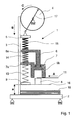
- Stapling device 1 substantially comprises a holddown element 9 with an associated first pressure spring 13 having a low spring force C1, a staple forming member 7 with an associated second pressure spring 14 having a spring force C2 which is greater than that of first pressure spring 13, a staple driving means 6 with an associated third pressure spring 15 having a spring force C3 which is greater than that of second pressure spring 14, a bending block 8 associated with staple forming member 7, an eccentric drive 4, 17 mounted in stationary fashion, and a drive head 5 associated with the latter and with third pressure spring 15.
- Holddown element 9, staple forming member 7, staple driving means 6, and drive head 5 are guided in linearly displaceable fashion on a support 3 of stapling device 1 in a known manner (not depicted).
- Staple driving means 6 on which staple forming member 7 is displaceably guided has in the guidance region a T-shaped extension 6b.
- Said extension 6b delimits the maximum distance between a projection 6a of staple driving means 6 and a projection 7a of staple forming member 7, with pressure spring 14 being arranged in preloaded fashion between said two projections 6a and 7a.
- pressure springs 13, 14, and 15 are defined as a function of the thickness of sheet stack 10 to be stapled and of the nature of the sheet and/or film material to be stapled, in such a way that, for example, pressure spring 15 has a preload force of 250 to 300 N, pressure spring 14 a preload force of 80 N, and pressure spring 13 a preload force of 20 N. If only thinner sheet stacks are to be stapled, a preload force of 100 N may then be sufficient for pressure spring 15.
- Staple wire 11 for the forming of staples 12 is delivered to stapling device 1 in the direction of the arrow "A" and is stored in known fashion (not depicted) on a wire spool. After delivery to stapling device 1, staple wire 11 is cut off, also in a known fashion (not depicted), to a length necessary for the staple size, the length of the cut-off wire segment being adaptable in known fashion to the sheet stack thickness to be stapled.
- the mode of operation of the device is as follows:
- the initial position of stapling device 1 depicted in Fig. 1 is determined by the inactive position of eccentric drive 4, 17 and the preloads of pressure springs 13, 14, and 15 acting on the individual components 5, 6, and 7, respectively, in which, as shown in Fig. 1, a lower limiting means 16 of stapling device 1 assumes a defined distance "a" from collecting station 2.
- eccentric drive 4 is set in rotary motion in the direction of the arrow "C".
- a crank rod articulated on eccentric drive 4 eccentrically with respect to the rotation axis thereof is joined at its other end to drive head 5, and moves the latter in the direction of the arrow "B".
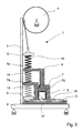
- the entire stapling device 1 is thereby moved, by means of the strongest third pressure spring 15, downward in the direction of the arrow "B", until holddown element 9 shown in Fig. 2 rests on sheet stack 10 and compresses it.
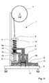
- the actual stapling operation is then performed by driving staple 12 into sheet stack 10, as shown in Fig. 4.
- staple driving means 6 which is driven by the eccentric drive 4, 17 and by the strongest third pressure spring 15 to overcome the force of the weaker second pressure spring 14 and to move staple driving means 6 in the direction of the arrow "B", thereby compressing second pressure spring 14.
- the legs of staple 12 are positively guided in a known fashion (not depicted) on lateral guide grooves of staple forming member 7.
- stapling device 1 After completion of the stapling operation, stapling device 1 is moved back in a direction opposite to the direction of the arrow "B", by means of eccentric drive 4, 17 rotating in the direction of the arrow "C”, into its raised initial position shown in Fig. 1; during this return movement, pressure springs 13, 14, 15 can spring back into their preloaded initial positions as shown in Fig. 1. During the return movement of stapling device 1, bending block 8 is pivoted back into its working position beneath staple forming member 7.
Landscapes
- Engineering & Computer Science (AREA)
- Mechanical Engineering (AREA)
- Life Sciences & Earth Sciences (AREA)
- Forests & Forestry (AREA)
- Dovetailed Work, And Nailing Machines And Stapling Machines For Wood (AREA)
- Portable Nailing Machines And Staplers (AREA)
- Folding Of Thin Sheet-Like Materials, Special Discharging Devices, And Others (AREA)
Claims (2)
- Heftvorrichtung zur Bildung von Heftklammern aus Draht (11) und zum Zusammenheften von einem Stapel Blätter (10) mittels dieser Heftklammern, bei der die Heftklammern anschließend in den Blattstapel eingetrieben werden,
dadurch gekennzeichnet,dass die Heftvorrichtung (1) einen Niederhalter (9), einen Klammerformer (7) und einen Klammereintreiber (6) aufweist, die linear geführt und senkrecht zur Stapeloberseite bewegbar sind,dass eine erste, eine zweite und eine dritte Druckfeder (13, 14, 15) mit gleichen Wirkungsrichtungen, jedoch mit jeweils unterschiedlicher Federkraft senkrecht zur Stapeloberseite angeordnet sind,dass die erste Druckfeder (13) an dem der Stapeloberseite zugeordneten Niederhalter (9) angreift und mit einer niedrigen Federkraft (C1) versehen ist,dass die zweite Druckfeder (14) dem Klammerformer (7) zugeordnet ist und eine Federkraft (C2) aufweist, die größer ist als die der ersten Druckfeder (13),dass die dritte Druckfeder (15) dem Klammereintreiber (6) zugeordnet ist und eine Federkraft (C3) aufweist, die größer ist als die der zweiten Druckfeder (14),dass die Druckfedern (13, 14, 15) von einem gemeinsamen, in der Wirkungsrichtung der Druckfedern (13, 14, 15) bewegbaren Antrieb (4, 17) der Heftvorrichtung (1) beaufschlagt werden,dass der Antrieb (4, 17) dem einen Ende der Druckfeder-Anordnung (13, 14, 15) zugeordnet ist unddass das andere Ende der Druckfeder-Anordnung (13, 14, 15) dem zu heftenden Blattstapel (10) zugewandt ist. - Heftvorrichtung nach Anspruch 1,
dadurch gekennzeichnet,dass die erste Druckfeder (13) zwischen dem Niederhalter (9) und dem Klammerformer (7, 7a) vorgespannt angeordnet ist,dass die zweite Druckfeder (14) zwischen dem Klammerformer (7, 7a) und dem Klammereintreiber (6, 6a) vorgespannt angeordnet ist unddass die dritte Druckfeder (15) zwischen dem Klammereintreiber (6, 6a) und einem vom Antrieb (4, 17) bewegbaren Widerlager (5) vorgespannt angeordnet ist.
Applications Claiming Priority (2)
| Application Number | Priority Date | Filing Date | Title |
|---|---|---|---|
| DE19752286 | 1997-11-26 | ||
| DE19752286A DE19752286A1 (de) | 1997-11-26 | 1997-11-26 | Heftvorrichtung |
Publications (2)
| Publication Number | Publication Date |
|---|---|
| EP0920963A1 EP0920963A1 (de) | 1999-06-09 |
| EP0920963B1 true EP0920963B1 (de) | 2003-04-02 |
Family
ID=7849814
Family Applications (1)
| Application Number | Title | Priority Date | Filing Date |
|---|---|---|---|
| EP98121695A Expired - Lifetime EP0920963B1 (de) | 1997-11-26 | 1998-11-13 | Heftvorrichtung |
Country Status (4)
| Country | Link |
|---|---|
| US (1) | US5996876A (de) |
| EP (1) | EP0920963B1 (de) |
| JP (1) | JPH11207652A (de) |
| DE (2) | DE19752286A1 (de) |
Families Citing this family (9)
| Publication number | Priority date | Publication date | Assignee | Title |
|---|---|---|---|---|
| SE525369C2 (sv) * | 2001-09-14 | 2005-02-08 | Isaberg Rapid Ab | Klammerformare i en häftapparat |
| DE102006000139B3 (de) * | 2006-03-28 | 2007-10-18 | Hilti Ag | Handgeführtes Eintreibgerät |
| MY193272A (en) | 2016-06-29 | 2022-09-29 | Valinge Innovation Ab | Method and device for inserting a tongue |
| JP7053506B2 (ja) * | 2016-06-29 | 2022-04-12 | ベーリンゲ、イノベイション、アクチボラグ | タングを挿入するための方法及び装置 |
| WO2018004440A1 (en) | 2016-06-29 | 2018-01-04 | Välinge Innovation AB | A method and device for managing and separating a tongue from a tongue blank |
| WO2018004435A1 (en) | 2016-06-30 | 2018-01-04 | Välinge Innovation AB | Device for inserting a tongue |
| US10953566B2 (en) | 2016-12-22 | 2021-03-23 | Valinge Innovation Ab | Device for inserting a tongue |
| EP3718437A1 (de) | 2019-04-05 | 2020-10-07 | Välinge Innovation AB | Verfahren zur montage eines möbelstücks |
| CN113561277B (zh) * | 2021-06-07 | 2022-07-08 | 杭州亚太智能装备有限公司 | 一种气动码钉枪 |
Family Cites Families (13)
| Publication number | Priority date | Publication date | Assignee | Title |
|---|---|---|---|---|
| US1705819A (en) * | 1926-07-02 | 1929-03-19 | Alexander Z Kruse | Stapling machine |
| FR779198A (fr) * | 1934-10-03 | 1935-03-30 | Machine à fabriquer et à poser les agrafes | |
| US2574875A (en) * | 1947-06-05 | 1951-11-13 | Bocjl Corp | Fastener driving device |
| US3231168A (en) * | 1963-11-18 | 1966-01-25 | Powers Wire Products Company I | Fastener forming and driving tool |
| DE7324364U (de) * | 1973-06-30 | 1981-02-26 | Fa. E.C.H. Will (Gmbh & Co), 2000 Hamburg | Heftkopf |
| DE2642896C3 (de) * | 1976-09-24 | 1980-08-21 | 7800 Freiburg | Präzisionsschnepper zum Setzen von Normstichwunden in die Haut für Diagnosezwecke |
| US4356947A (en) * | 1978-12-29 | 1982-11-02 | Xerox Corporation | Stitchers |
| US4318555A (en) * | 1980-01-15 | 1982-03-09 | Eastman Kodak Company | Stapler |
| US4557410A (en) * | 1983-08-30 | 1985-12-10 | International Business Machines Corporation | Stapler mechanism powering means |
| JPS6279977A (ja) * | 1985-09-24 | 1987-04-13 | キヤノン株式会社 | ステ−プラ−の針送り装置 |
| EP0379457A3 (de) * | 1989-01-18 | 1990-10-10 | Tolemecane S.A.R.L. | Bewegliches Gerät für das Einsetzen von Stapeln und Stapel dafür |
| ES2042139T3 (es) * | 1989-05-25 | 1993-12-01 | Ferag Ag | Aparato encuadernador. |
| DE4020355C2 (de) * | 1990-06-27 | 1996-02-29 | Kodak Ag | Heftvorrichtung zum Zusammenheften von Blättern |
-
1997
- 1997-11-26 DE DE19752286A patent/DE19752286A1/de not_active Withdrawn
-
1998
- 1998-10-30 JP JP10309686A patent/JPH11207652A/ja active Pending
- 1998-11-13 EP EP98121695A patent/EP0920963B1/de not_active Expired - Lifetime
- 1998-11-13 DE DE69812851T patent/DE69812851T2/de not_active Expired - Fee Related
- 1998-11-19 US US09/195,907 patent/US5996876A/en not_active Expired - Fee Related
Also Published As
| Publication number | Publication date |
|---|---|
| DE19752286A1 (de) | 1999-05-27 |
| US5996876A (en) | 1999-12-07 |
| JPH11207652A (ja) | 1999-08-03 |
| DE69812851T2 (de) | 2004-03-04 |
| DE69812851D1 (de) | 2003-05-08 |
| EP0920963A1 (de) | 1999-06-09 |
Similar Documents
| Publication | Publication Date | Title |
|---|---|---|
| EP0920963B1 (de) | Heftvorrichtung | |
| EP0099249B1 (de) | Drahtheftmaschine | |
| US7621433B2 (en) | Stapler | |
| US5330086A (en) | Electromotive stapler | |
| WO1998047669A1 (en) | Stapler with internal guidance of the legs of a staple | |
| JP4524868B2 (ja) | 電動ホッチキス | |
| US6616029B1 (en) | Stapler with reversible electric motor | |
| US4995542A (en) | Stapling apparatus for fixing junction staples on the end of a conveyor belt or the like | |
| US7121440B2 (en) | Motor-driven stapler having a driver and a cylinder unit that vertically reciprocates | |
| US5921455A (en) | Stapling device | |
| EP1655109B1 (de) | Verriegelungsmechanismus für papierheftdrucktisch | |
| EP0381226B1 (de) | Vorrichtung zum Schützen eines Lichtmarkenprojektors vor einem Anprall mit dem Stempel einer Maschine zum Ansetzen von Knöpfen | |
| EP1535709B1 (de) | Elektrische heftmaschine und verfahren zum einbinden von blätter und erstellen einer biegelinie | |
| US20060266787A1 (en) | Electric stapler | |
| JP4330858B2 (ja) | ステープラー内のステープル形成機構 | |
| JP3975354B2 (ja) | ステープラーにおけるリターン機構 | |
| EP0381227B1 (de) | Schlaganpassungsvorrichtung für den Lichtmarkenprojektor einer Maschine zum Ansetzen von Knöpfen | |
| EP4338907B1 (de) | Bilderzeugungssystem, nachbearbeitungsvorrichtung und bindevorrichtung | |
| JP4304971B2 (ja) | 電動ステープラーにおける紙厚調整機構 | |
| EP1577061B1 (de) | Elektrischer Heftapparat | |
| EP2519385B1 (de) | Magazineinheit für fixiermittelstreifen | |
| EP1733856B1 (de) | Klammermaschine mit eigenantrieb | |
| JPH0741547B2 (ja) | マガジン固定型電動ホッチキス | |
| JPH0528961B2 (de) | ||
| US20150367489A1 (en) | Stapler |
Legal Events
| Date | Code | Title | Description |
|---|---|---|---|
| PUAI | Public reference made under article 153(3) epc to a published international application that has entered the european phase |
Free format text: ORIGINAL CODE: 0009012 |
|
| AK | Designated contracting states |
Kind code of ref document: A1 Designated state(s): DE FR GB |
|
| AX | Request for extension of the european patent |
Free format text: AL;LT;LV;MK;RO;SI |
|
| K1C1 | Correction of patent application (title page) published |
Effective date: 19990609 |
|
| 17P | Request for examination filed |
Effective date: 19991117 |
|
| AKX | Designation fees paid |
Free format text: DE FR GB |
|
| RAP1 | Party data changed (applicant data changed or rights of an application transferred) |
Owner name: NEXPRESS SOLUTIONS LLC |
|
| GRAH | Despatch of communication of intention to grant a patent |
Free format text: ORIGINAL CODE: EPIDOS IGRA |
|
| GRAH | Despatch of communication of intention to grant a patent |
Free format text: ORIGINAL CODE: EPIDOS IGRA |
|
| GRAA | (expected) grant |
Free format text: ORIGINAL CODE: 0009210 |
|
| AK | Designated contracting states |
Designated state(s): DE FR GB |
|
| PG25 | Lapsed in a contracting state [announced via postgrant information from national office to epo] |
Ref country code: FR Free format text: LAPSE BECAUSE OF FAILURE TO SUBMIT A TRANSLATION OF THE DESCRIPTION OR TO PAY THE FEE WITHIN THE PRESCRIBED TIME-LIMIT Effective date: 20030402 |
|
| REG | Reference to a national code |
Ref country code: GB Ref legal event code: FG4D Free format text: NOT ENGLISH |
|
| REF | Corresponds to: |
Ref document number: 69812851 Country of ref document: DE Date of ref document: 20030508 Kind code of ref document: P |
|
| PG25 | Lapsed in a contracting state [announced via postgrant information from national office to epo] |
Ref country code: GB Free format text: LAPSE BECAUSE OF NON-PAYMENT OF DUE FEES Effective date: 20031113 |
|
| PLBE | No opposition filed within time limit |
Free format text: ORIGINAL CODE: 0009261 |
|
| STAA | Information on the status of an ep patent application or granted ep patent |
Free format text: STATUS: NO OPPOSITION FILED WITHIN TIME LIMIT |
|
| EN | Fr: translation not filed | ||
| 26N | No opposition filed |
Effective date: 20040105 |
|
| GBPC | Gb: european patent ceased through non-payment of renewal fee |
Effective date: 20031113 |
|
| PGFP | Annual fee paid to national office [announced via postgrant information from national office to epo] |
Ref country code: DE Payment date: 20051130 Year of fee payment: 8 |
|
| PG25 | Lapsed in a contracting state [announced via postgrant information from national office to epo] |
Ref country code: DE Free format text: LAPSE BECAUSE OF NON-PAYMENT OF DUE FEES Effective date: 20070601 |