EP0920992A2 - Machine à imprimer - Google Patents
Machine à imprimer Download PDFInfo
- Publication number
- EP0920992A2 EP0920992A2 EP98119980A EP98119980A EP0920992A2 EP 0920992 A2 EP0920992 A2 EP 0920992A2 EP 98119980 A EP98119980 A EP 98119980A EP 98119980 A EP98119980 A EP 98119980A EP 0920992 A2 EP0920992 A2 EP 0920992A2
- Authority
- EP
- European Patent Office
- Prior art keywords
- impression cylinder
- cylinder
- motor
- drives
- gear
- Prior art date
- Legal status (The legal status is an assumption and is not a legal conclusion. Google has not performed a legal analysis and makes no representation as to the accuracy of the status listed.)
- Withdrawn
Links
Images
Classifications
-
- B—PERFORMING OPERATIONS; TRANSPORTING
- B41—PRINTING; LINING MACHINES; TYPEWRITERS; STAMPS
- B41F—PRINTING MACHINES OR PRESSES
- B41F13/00—Common details of rotary presses or machines
- B41F13/08—Cylinders
- B41F13/10—Forme cylinders
- B41F13/12—Registering devices
- B41F13/14—Registering devices with means for displacing the cylinders
-
- B—PERFORMING OPERATIONS; TRANSPORTING
- B41—PRINTING; LINING MACHINES; TYPEWRITERS; STAMPS
- B41P—INDEXING SCHEME RELATING TO PRINTING, LINING MACHINES, TYPEWRITERS, AND TO STAMPS
- B41P2213/00—Arrangements for actuating or driving printing presses; Auxiliary devices or processes
- B41P2213/70—Driving devices associated with particular installations or situations
- B41P2213/73—Driving devices for multicolour presses
- B41P2213/734—Driving devices for multicolour presses each printing unit being driven by its own electric motor, i.e. electric shaft
Definitions
- the invention relates to a printing press with an impression cylinder and at least one inking unit that can be set on the impression cylinder
- Printing cylinder and an applicator roller that can be adjusted to the printing cylinder has, as well as with a motor that transmits the impression cylinder drives one additional motor for direct drive of the printing cylinder and the application roller, displacement sensors, which are the drives for assigned the impression cylinder, the impression cylinder and the application roller are, and a control device for controlling these drives.
- the print quality that can be achieved with a printing machine largely depends from that between the impression cylinder and the impression cylinders and inking rollers of the inking units a precise synchronous operation is maintained. In conventional printing machines, this is mostly done mechanically Paths achieved by the inking units via a on the shaft of the impression cylinder arranged gear are driven. In some use cases it proves to be a disadvantage that between the impression cylinder and the pressure cylinder only discrete speed ratios possible are. Printing machines with individual drives are therefore proposed been in those for the impression cylinder, the impression cylinder and the applicator roller each have separate electric motors which are provided by an electronic control system can be synchronized.
- the impression cylinder has a relative large diameter, and therefore it has a correspondingly large Moment of inertia while its speed is relatively low. If the motor for the impression cylinder directly on the shaft of this cylinder is therefore a low-revving motor with high torque needed.
- Such engines are relatively bulky and expensive.
- the object of the invention is to synchronize in a printing press of this type of the impression cylinder and the synchronous operation of the various cylinders and improve rollers.
- impression cylinder drive assigned displacement sensor is arranged on the shaft of the impression cylinder.
- This disadvantage is avoided according to the invention in that the displacement sensor for the impression cylinder drive directly on the shaft of the impression cylinder is arranged.
- This encoder therefore always delivers a reliable one Measure of the actual angular velocity of the impression cylinder, see above that a greater tolerance to transmission errors in the transmission is achieved becomes. Due to the comparatively large moment of inertia of the impression cylinder at most, its angular velocity changes very much slowly. Therefore, when measuring this angular velocity there is none high angular resolution required. Because the moment of inertia of the gear and the motor is significantly smaller, the transmission errors of the transmission result primarily to engine speed changes. These speed changes However, according to the invention, they are not reported back to the control system, so that unnecessary control interventions are avoided.
- the angular velocity of the Back pressure cylinder regulates to a target value, so result from the high moment of inertia of the impression cylinder only small target / actual deviations.
- the motor is controlled so that its angular velocity varies and thereby compensates for the transmission errors of the transmission become.
- the very constant and precisely recorded actual angular velocity of the impression cylinder is suitable as a reference variable for the control of the inking unit drives according to the master / slave principle.
- the transmission errors in the transmission result relative changes in the angular velocities of the motor and the impression cylinder, which follow a periodic pattern. If for example, the transmission from a drive pinion seated on the shaft of the motor and one sitting on the shaft of the impression cylinder Gear with a large diameter, the period corresponds to relative changes in angular velocities caused by gear errors the smallest common multiple of the number of teeth the drive pinion and the gear.
- the control system for the impression cylinder drive can then be designed to accommodate these periodic changes "foresighted" considered.
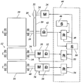
- the only drawing figure shows a drive diagram for an impression cylinder and an inking unit of a flexographic printing machine and a block diagram an associated control device.
- an impression cylinder 10 of a flexographic printing machine On the circumference of an impression cylinder 10 of a flexographic printing machine arranged several inking units 12, each having a printing cylinder 14 and an application roller 16, for example an anilox roller.
- a gear 20 On the shaft 18 of the impression cylinder 10, a gear 20 is seated a much smaller drive pinion 22 meshes.
- the drive pinion 22 sits on the output shaft 24 of a motor 26, for example an asynchronous motor.
- the drive pinion 22 and the gear 20 thus form a gear 28, via which the impression cylinder 10 with a greatly reduced speed is driven by the motor 26.
- the motor 26 therefore only needs to have a low drive torque and accordingly has small Dimensions.
- a motor 30 for the pressure cylinder 14 and an associated displacement sensor 32 are seated directly on the shaft 34 of the impression cylinder.
- a motor is accordingly 36 for the application roller 16 and an associated displacement sensor 38 directly on the Shaft 40 of the applicator roller arranged.
- a displacement sensor 42 for the impression cylinder 10 is separate from the motor 26 arranged on the shaft 18 of the impression cylinder and thus detected immediately the angular velocity of the impression cylinder 10 without Adulteration due to possible gearing errors between the drive pinion 22 and the gear 20.
- the position sensors 32, 38 and 42 provide digital angular velocity or Increment signals to a control device 44.
- This control device has a setpoint generator 46, which has a setpoint for the angular velocity or the respective angle of rotation of the impression cylinder 10 to one Controller 48 delivers.
- the controller 48 compares this setpoint with that of Position sensor 42 supplied actual value and delivers a corresponding control signal to the engine 26.
- the ratio the angular velocity of the impression cylinder 10 to the angular velocity of the motor 26 temporarily increases, this is due to of the large moment of inertia of the impression cylinder 10 in the first Line in a decrease in the angular velocity of the motor 26 while the increase in the angular velocity of the impression cylinder 10 is minimal.
- this increase in angular velocity is so small is that it is not detected by the travel sensor 42, there is no control intervention through the controller 48, that is, the decrease in angular velocity the motor 26 is not compensated, so that the impression cylinder 10 continues at a substantially constant speed.
- the actual speed reported by the travel sensor 42 therefore forms one suitable reference variable for the drive control of the pressure cylinder 14 and the pressure roller 16.
- the signal from the displacement sensor 42 is therefore also a Setpoint generator 50 supplied, based on this signal, if necessary Taking into account the control intervention initiated by the controller 48, a setpoint for the angular speeds or angular increments of the impression cylinder 14 and the application roller 16 generated.
- the signals from the displacement sensors 32 and 38 are a precise measure of the angular velocity or the angular increment of the printing cylinder 14 or the pressure roller 16 represent a controller 52 and 54 are supplied and compared there with the signal of the setpoint generator 50. From this The target / actual comparison is made through control interventions on the motors 30 and 36 the actual angular velocities of the impression cylinder and the pressure roller regulated to the setpoint. Since this setpoint is directly from the actual value of the Angular velocity of the impression cylinder 10 is derived, a precise synchronous operation of the printing cylinder 14 and the pressure roller 16 with the impression cylinder 10 reached.
Landscapes
- Engineering & Computer Science (AREA)
- Mechanical Engineering (AREA)
- Inking, Control Or Cleaning Of Printing Machines (AREA)
- Rotary Presses (AREA)
Applications Claiming Priority (2)
| Application Number | Priority Date | Filing Date | Title |
|---|---|---|---|
| DE1997154323 DE19754323A1 (de) | 1997-12-08 | 1997-12-08 | Druckmaschine |
| DE19754323 | 1997-12-08 |
Publications (2)
| Publication Number | Publication Date |
|---|---|
| EP0920992A2 true EP0920992A2 (fr) | 1999-06-09 |
| EP0920992A3 EP0920992A3 (fr) | 2000-01-05 |
Family
ID=7851073
Family Applications (1)
| Application Number | Title | Priority Date | Filing Date |
|---|---|---|---|
| EP98119980A Withdrawn EP0920992A3 (fr) | 1997-12-08 | 1998-10-22 | Machine à imprimer |
Country Status (3)
| Country | Link |
|---|---|
| EP (1) | EP0920992A3 (fr) |
| JP (1) | JPH11227166A (fr) |
| DE (1) | DE19754323A1 (fr) |
Cited By (2)
| Publication number | Priority date | Publication date | Assignee | Title |
|---|---|---|---|---|
| EP4360882A1 (fr) * | 2022-10-27 | 2024-05-01 | Bundesdruckerei GmbH | Dispositif d'impression pour l'impression iridescente |
| EP4360881A1 (fr) * | 2022-10-27 | 2024-05-01 | Bundesdruckerei GmbH | Dispositif d'impression et procédé d'impression pour une numérotation multicolore |
Families Citing this family (3)
| Publication number | Priority date | Publication date | Assignee | Title |
|---|---|---|---|---|
| DE10327218B4 (de) * | 2003-06-17 | 2015-08-06 | Schaeffler Technologies AG & Co. KG | Direktantrieb für einen Zylinder einer Druckmaschine |
| CH697884B1 (de) * | 2004-07-13 | 2009-03-13 | Manroland Ag | Rollenrotationsdruckeinheit. |
| DE102006013636B4 (de) * | 2006-03-22 | 2012-02-09 | Siemens Ag | Druckmaschine bzw. elektrische Maschine für eine Druckmaschine |
Family Cites Families (9)
| Publication number | Priority date | Publication date | Assignee | Title |
|---|---|---|---|---|
| DE2943894C3 (de) * | 1979-03-19 | 1982-08-05 | Gerhard Ing.(grad.) 4800 Bielefeld Klemm | Vorrichtung zum Transport von luftundurchlässigen Warenbahnen, wie Papier- oder Folienbahnen |
| GB2146291B (en) * | 1983-09-14 | 1987-10-14 | Grace W R & Co | Rotary printing press |
| DE3729911A1 (de) * | 1987-09-07 | 1989-03-23 | Braun Gmbh Ind Elektronik | Gleichlauf-regelung von bearbeitungsstationen |
| DE4344896C5 (de) * | 1993-12-29 | 2004-07-29 | Maschinenfabrik Wifag | Antrieb für Zylinder einer Rollenrotationsdruckmaschine |
| DE19529430C2 (de) * | 1995-07-06 | 2000-07-13 | Baumueller Nuernberg Gmbh | Elektrisches Antriebssystem zur Verstellung von mehreren dreh- und/oder verschwenkbaren Funktionsteilen |
| DE19527199C2 (de) * | 1995-07-26 | 2002-10-31 | Baumueller Nuernberg Gmbh | Flexodruckmaschine und deren Verwendung |
| US5615609A (en) * | 1995-08-21 | 1997-04-01 | The Lawrence Paper Company | System and method for controlling AC motor driven multi-unit printing press |
| DE19537587C2 (de) * | 1995-10-09 | 1998-02-26 | Koenig & Bauer Albert Ag | Antriebsregeleinrichtung für einen Mehrmotorenantrieb einer Druckmaschine |
| DE19623223C2 (de) * | 1996-06-11 | 2001-05-17 | Roland Man Druckmasch | Antrieb für eine Druckmaschine |
-
1997
- 1997-12-08 DE DE1997154323 patent/DE19754323A1/de not_active Withdrawn
-
1998
- 1998-10-22 EP EP98119980A patent/EP0920992A3/fr not_active Withdrawn
- 1998-11-25 JP JP10333713A patent/JPH11227166A/ja active Pending
Cited By (2)
| Publication number | Priority date | Publication date | Assignee | Title |
|---|---|---|---|---|
| EP4360882A1 (fr) * | 2022-10-27 | 2024-05-01 | Bundesdruckerei GmbH | Dispositif d'impression pour l'impression iridescente |
| EP4360881A1 (fr) * | 2022-10-27 | 2024-05-01 | Bundesdruckerei GmbH | Dispositif d'impression et procédé d'impression pour une numérotation multicolore |
Also Published As
| Publication number | Publication date |
|---|---|
| DE19754323A1 (de) | 1999-06-10 |
| EP0920992A3 (fr) | 2000-01-05 |
| JPH11227166A (ja) | 1999-08-24 |
Similar Documents
| Publication | Publication Date | Title |
|---|---|---|
| EP0812682B1 (fr) | Entraínement pour une machine à imprimer | |
| EP0699524B2 (fr) | Machine rotative d'impression offset à bobines | |
| DE19527199C2 (de) | Flexodruckmaschine und deren Verwendung | |
| DE4345570B4 (de) | Antrieb für Zylinder einer Rotationsdruckmaschine | |
| EP0930160B1 (fr) | Machine d'impression rotative | |
| EP0812683B1 (fr) | Entraínement pour une machine à imprimer | |
| DE3828638C1 (fr) | ||
| EP0846555B1 (fr) | Entraínement pour une machine à imprimer | |
| EP0081186B1 (fr) | Procédé et dispositif pour diminuer les fautes de repérage dans des machines à imprimer rotatives à plusieurs couleurs | |
| EP0709184B1 (fr) | Dispositif pour éviter des défauts de repérage | |
| DE10246072B4 (de) | Rotationsdruckverfahren für Mehrfarbendruck | |
| DE2617418A1 (de) | Vorschubsteuervorrichtung | |
| DE4344896C5 (de) | Antrieb für Zylinder einer Rollenrotationsdruckmaschine | |
| DE4228506A1 (de) | Verfahren und Antrieb für eine Druckmaschine mit mehreren Druckwerken | |
| DE19754323A1 (de) | Druckmaschine | |
| DE4344912C2 (de) | Antrieb eines farbübertragenden Druckzylinders einer Rollenrotationsdruckmaschine | |
| EP0692377B1 (fr) | Procédé et dispositif pour l'entraínement synchrone de composants d'une machine d'impression | |
| DE4316261B4 (de) | Mehrmotorenantrieb für eine Bogen-Offset-Rotationsdruckmaschine | |
| DE3644445C2 (fr) | ||
| DE10212534B4 (de) | Verfahren zum Antreiben einer Druckmaschine | |
| DE19826338A1 (de) | Antrieb für eine Druckmaschine | |
| EP1156382B1 (fr) | Méthode et appareil pour l'ajustement de registre dans une imprimante couleur | |
| DE102005014060B4 (de) | Farbwerk einer Druckmaschine | |
| DE29513635U1 (de) | Rotationsdruckmaschine mit Zylindern, die zu motorisch einzeln angetriebenen Zylindergruppen zusammengefaßt sind | |
| DE20104946U1 (de) | Rotationsdruckmaschine |
Legal Events
| Date | Code | Title | Description |
|---|---|---|---|
| PUAI | Public reference made under article 153(3) epc to a published international application that has entered the european phase |
Free format text: ORIGINAL CODE: 0009012 |
|
| AK | Designated contracting states |
Kind code of ref document: A2 Designated state(s): AT BE CH CY DE DK ES FI FR GB GR IE IT LI LU MC NL PT SE |
|
| AX | Request for extension of the european patent |
Free format text: AL;LT;LV;MK;RO;SI |
|
| PUAL | Search report despatched |
Free format text: ORIGINAL CODE: 0009013 |
|
| AK | Designated contracting states |
Kind code of ref document: A3 Designated state(s): AT BE CH CY DE DK ES FI FR GB GR IE IT LI LU MC NL PT SE |
|
| AX | Request for extension of the european patent |
Free format text: AL;LT;LV;MK;RO;SI |
|
| AKX | Designation fees paid | ||
| REG | Reference to a national code |
Ref country code: DE Ref legal event code: 8566 |
|
| STAA | Information on the status of an ep patent application or granted ep patent |
Free format text: STATUS: THE APPLICATION IS DEEMED TO BE WITHDRAWN |
|
| 18D | Application deemed to be withdrawn |
Effective date: 20000706 |