EP0921029A2 - Siège de véhicule à dossier rabattable - Google Patents
Siège de véhicule à dossier rabattable Download PDFInfo
- Publication number
- EP0921029A2 EP0921029A2 EP98250417A EP98250417A EP0921029A2 EP 0921029 A2 EP0921029 A2 EP 0921029A2 EP 98250417 A EP98250417 A EP 98250417A EP 98250417 A EP98250417 A EP 98250417A EP 0921029 A2 EP0921029 A2 EP 0921029A2
- Authority
- EP
- European Patent Office
- Prior art keywords
- locking pawl
- control
- locking
- vehicle seat
- stop
- Prior art date
- Legal status (The legal status is an assumption and is not a legal conclusion. Google has not performed a legal analysis and makes no representation as to the accuracy of the status listed.)
- Granted
Links
- 238000000034 method Methods 0.000 claims description 7
- 230000008569 process Effects 0.000 claims description 7
- 210000003813 thumb Anatomy 0.000 claims description 6
- 210000003811 finger Anatomy 0.000 claims description 5
- 230000009471 action Effects 0.000 description 5
- 238000010276 construction Methods 0.000 description 4
- 230000000694 effects Effects 0.000 description 3
- 238000005516 engineering process Methods 0.000 description 2
- 230000003993 interaction Effects 0.000 description 2
- 230000008901 benefit Effects 0.000 description 1
- 230000000052 comparative effect Effects 0.000 description 1
- 230000000977 initiatory effect Effects 0.000 description 1
- 238000009434 installation Methods 0.000 description 1
- 230000007257 malfunction Effects 0.000 description 1
- 230000007246 mechanism Effects 0.000 description 1
- 230000004048 modification Effects 0.000 description 1
- 238000012986 modification Methods 0.000 description 1
- 239000013641 positive control Substances 0.000 description 1
- 230000000284 resting effect Effects 0.000 description 1
- 230000000630 rising effect Effects 0.000 description 1
Images





Classifications
-
- B—PERFORMING OPERATIONS; TRANSPORTING
- B60—VEHICLES IN GENERAL
- B60N—SEATS SPECIALLY ADAPTED FOR VEHICLES; VEHICLE PASSENGER ACCOMMODATION NOT OTHERWISE PROVIDED FOR
- B60N2/00—Seats specially adapted for vehicles; Arrangement or mounting of seats in vehicles
- B60N2/02—Seats specially adapted for vehicles; Arrangement or mounting of seats in vehicles the seat or part thereof being movable, e.g. adjustable
- B60N2/20—Seats specially adapted for vehicles; Arrangement or mounting of seats in vehicles the seat or part thereof being movable, e.g. adjustable the back-rest being tiltable, e.g. to permit easy access
Definitions
- the present invention relates to a vehicle seat foldable backrest, which is swivel-mounted on the adapters Seat frame is held, which has a locking pawl a pivot pin pivotally in the closed position grips a stop fixed to the seat part with her ratchet mouth and can be unlocked by means of a release link.
- the backrest is usually in a motor vehicle seat adjustable in inclination relative to the seat part to the Backrest of different body sizes and seating habits optimally adapt. Regardless of this inclination setting the backrest is at the relevant level here Technology stored on the seat part between two end positions. In a first end position, the so-called use position, the backrest is swung back and against it Fold down locked in front. After releasing a lock the backrest can be folded down by hand in the direction of travel, until the upper end of the backrest abuts the steering wheel. This solution is particularly advantageous for two-door cars, to make it easier for people to get into the rear.
- the object of the present invention is for a vehicle seat of the type mentioned at the outset make no additional components to secure the Close position of the locking pawl is required, so very much is simple and yet safe.
- this construction also has the same effect as when standing described the technology in the event of a crash on the torque Locking pawl. While this is in the prior art a "wandering" of the stop in the swivel direction open latch mouth and thus an opening of the locking latch causes, it can be in the solution according to the invention Do not have any effect as the locking pawl is already after a short swivel path around the seat part fixed stop with your Slotted wall strikes the bearing pin. Because about it no more clamping surface is required on the jack mouth, the system between the stop and the jack mouth can be designed in this way be that the locking pawl not in the event of a crash is released from the attack, essentially at this point There is self-locking. This ensures that the locking pawl does not open in the event of a crash. Additional components to secure the locking pawl in its closed position are not required.
- Another advantage of the invention is that the state of the art to compensate for wear-related Tolerances required undercut of the ratchet mouth is not necessary as this is laid in the slot is. As a result, the jack mouth can be shorter and thus the locking pawl be made weaker (weight saving).
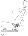
- Fig. 1 shows a vehicle seat 1 with a seat part 2, one Backrest 3 and a headrest 4.
- the vehicle seat 1 is via a seat height adjustment 5 on a seat rail 6 of the Motor vehicle stored.
- the backrest 3 is via adapter 7, the connection to the usual inclination adjustment fittings 14 produce, foldable on both sides around bolt 8 on the load-bearing Structure of the seat part 2 attached.
- the adapters 7 lie on a stop pin 9, which is rigid with the supporting structure of the seat part 2 is connected or belongs to this.
- the stop pin 9 is from a with backrest in use Includes pivotally mounted on the adapter 7 locking pawl 10. This locking mechanism allows the backrest to be folded forward 3 prevented in direction 11.
- an actuator 12 is arranged.
- Fig. 1 is used to view all of the following Embodiments.
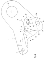
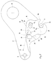
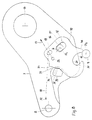
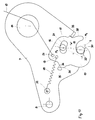
- Figures 2 to 4 show one of the adapters 7 in an enlarged view and simplified representation according to a first embodiment the invention.
- Vehicle seat As points of reference to what is no longer shown Vehicle seat are the seat part-fixed bolt 8, as a circle simplifies the inclination adjustment fitting 14 and the seat part fixed Stop pin 9 drawn.
- Backrest 3 (Fig. 1) are the adapters 7 with their at this point concave bottom 15 on the stop pin 9 on.
- the locking pawl 10 is on an adapter-fixed bearing pin 16 stored and provided with an elongated hole 17, through which the bearing pin 16 projects.
- the bolt 16 is as Head rivet executed, the head of the contours of the slot 17th overlaps laterally, causing the locking pawl to lift off 10 is prevented by the adapter 7 (not shown).
- FIG. 2 The crash situation shown in FIG. 2 is a snapshot, the locking pawl 10 shortly before initiation of a wanted Opening process or in the position it shows a front crash, which is explained in more detail below.
- the locking pawl 10 by one in FIGS. 2 to 4 only symbolically with a Dash-dot line applied tension spring 18, the into a pin 19 provided on the locking pawl 10 is attached.
- This pin 19 is on the pawl mouth 20th opposite end of the locking pawl 10 is arranged. Due to the force of the tension spring 18, the locking pawl 10 pivoted counterclockwise around the stop pin 9. As a result, the bearing pin 16 moves relatively in slot 17 clockwise.
- the above-mentioned design freedom on the ratchet mouth 20 is further used in that the stop pin 9 of bottom contact surface of the ratchet jaw 20 on a radius r is about the central axis M1 of the bearing pin 16 if this is in the crash situation (Fig. 2).
- the tension spring 18 suspended in the locking pawl 10 is with its other end in a lever arm 24 of a control plate 22 hung, which is pivotable on a pin 23 on the adapter 7 is attached.
- the control plate 22 has a control thumb 25, the lever arm 24, based on the pivot axis of the control plate 22 forming pin 23, arranged diametrically opposite is.
- the control thumb 25 lies on the stop bolt from above 9, causing the control plate 22 to pivot the pin 23 is prevented clockwise. This is also ensures that the lever arm 24 is a fixed abutment for the Tension spring 18 forms, i.e. that this in the sense described above can act on the locking pawl 10.
- the center axis M1 of the bearing pin acts 16 and M2 of the stop bolt 9 connecting line W a strong traction on the locking pawl 10, which strives is the distance between the stop pin 9 and the bearing pin 16 to enlarge, i.e. to fold the backrest 3 forward. Since the bearing pin 16 on the as an increasing clamping surface acting wall 21 of the elongated hole 17 results from this tensile force a torque that the locking pawl 10th pivoted clockwise until the bearing pin 16 on the left wall of the elongated hole 17 strikes (Fig. 2).
- the locking pawl 10 engages under the effect of Tension spring 18 with a latch provided at its upper end 27 in the end of a locking arm 28 of the control plate 22.
- she lies with her back on an adapter-fixed one Cam 29 and is thus together with the control plate 22 fixed against pivoting in both directions, i.e. it retains the one shown in FIG. 4 when the backrest 3 is folded Position, even after the control thumb 25 of the control plate 22nd no longer rests on the stop pin 9, at.
- the locking pawl 10 is thus secured in its open position.
- the backrest is folded back to produce the position of use.
- the control thumb 25 of the control plate strikes 22 on the stop pin 9 and turns the control plate 22 in Counter-clockwise around the pin 23. This brings the locking pawl 10 free from the locking arm 28 of the control plate 22, and the tension spring 18 pulls the locking pawl 10 in the play-free closed position according to FIG. 3.
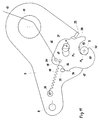
- 5-9 is a second embodiment of the present Invention shown.
- Components that match those of the first Embodiment are identical or equivalent, wear the same reference numerals as the corresponding components of the first embodiment.
- Control plate 22 for omission which is an additional moving Component represents and thus possibly to malfunctions can lead.
- the function of the control plate 22 takes over Control cam 35 in interaction with one on the ratchet mouth 20 trained control finger 38.
- the control cam 35 is from the Adapter 7 pushed out. This training helps to save weight at.
- the control cam 35 has a holding edge 36 and a control surface 37. It is in the neighborhood of Rear of the locking pawl 10 arranged, the rear formed as a control surface 33 with a control nose 34 is.
- control cam 35 The interaction of the control cam 35 with the control surface 33 of the locking pawl 10 is described below using an unlocking and locking process of the backrest 3, starting from the play-free closed position shown in FIG. 6, explained.
- FIGs 8 and 9 are two possible investment positions the control surfaces 37 and 33 shown.
- Fig. 8 shows the maximum possible unlocking position of the locking pawl 10, which reached with a correspondingly long train path of the Bowden cable 13 9, while the situation that occurs on At the end of the unlocking process. Is in this position the control lug 34 behind the retaining edge 36 of the control cam 35 locked. The locking pawl 10 is thus in its open position secured.
- the locking pawl 10 After each unlocking process, the locking pawl 10 automatically moves from the position shown in FIG. 8 or also from any intermediate position into the folding position according to FIG. 9.
- the control surface 33 of the locking pawl 10 also lies in this area on a circular arc around the central axis M 1 of the bearing pin 16. After the Bowden cable 13 has been released, the two control surfaces 33 and 37 slide against one another under the action of the tension spring 18. until the control lug 34 engages behind the retaining edge 36 of the control cam 35.
- the locking pawl 10 is therefore forced at this stage, so that an impact of the Nose 30 of the ratchet mouth 20 on the stop pin 9 excluded is. Only when the control nose 34 off the control surface 37 comes free (Fig. 5), the tension spring 18, the locking pawl 10 continue to pivot counterclockwise so that again a play-free locking position (Fig. 6 and 7) sets. Otherwise this applies to this embodiment the first embodiment said.
- the slot 17 compared to the above embodiments beyond the crash position in the opening direction is elongated, it has approximately a bean-shaped contour.
- the bearing pin 16 has seen relatively here, in contrast to the other embodiments, the possibility in slot 17 counterclockwise over its crash location to postpone further.
- the locking pawl 10 on its front a stop 39 angled by the adapter 7.
- the stop 39 secures, especially in the case of stiffness, this positive control of the locking pawl 10, in other words, it prevents the locking pawl 10 pivots further about the stop pin 9, but with further Train on Bowden cable 13 forcibly opens.
- This situation is in Fig. 12 shown.
- Control finger 38 of the pawl mouth 20 further clockwise, until the bearing pin 16 to the left, based on the drawing Wall of the slot 17 is present. Now is the maximum unlock position the locking pawl 10 is reached. This situation is apparent from Fig. 13.
- FIGS. 11, 10, 12 and 13 A comparative consideration of FIGS. 11, 10, 12 and 13 shows that on the back of the locking pawl 10th arranged control lug 34 during the opening movement of the locking pawl 10 constraint-free on the adapter-fixed control cam 35 has passed. If the Bowden cable 13 is now in the position shown in FIG. 13 shown, maximum unlocked position released, pulls the tension spring 18 the locking pawl 10 in the counterclockwise direction in contact with the control cam 35 so that the retaining lug 34 of the Locking pawl 10 behind the holding edge 36 of the control cam 35 locked, as is apparent from Fig. 14, the folding position the locking pawl 10 shows. The backrest 3 Locking pawl 10 is securely maintained because of this the tension spring 18 is held in contact with the control cam 35.
- the nose 30 of the ratchet mouth 20 lightly wash the stop pin 9, which by the Dashed line 31 is indicated. However, this is not harmful because the locking pawl 10 only slightly clockwise is pivoted, but without her control nose 34th is released from the control cam 35.
- the elongation of the elongated hole 17 described above is used in the presence of two or more locking pawls 10 the tolerance compensation for unequal rope lengths Bowden cables 13.
- the locking pawls 10 always the maximum unlocking position shown in FIG. 13 reached (actuator 12 pulled to the maximum), guaranteed the extension of the elongated hole 17 of each locking pawl 10, that the other or other locking pawl (s) 10 at least reached or reach a position according to FIG. 12 which is a minimum Unlocking position from which the backrest 3rd can also be easily folded forward.
- FIG. 12 which is a minimum Unlocking position from which the backrest 3rd can also be easily folded forward.
- FIG. 12 shows that the control lug 34 of the locking pawl 10 the Holding edge 36 of the control cam 35 has not yet passed, but held by the tension spring 18 against the control cam 35.
- the locking pawl 10 is therefore still for the folding process not secured in their position. But that happens through the Folding process itself.
- Fig. 12 is by the dashed line 31 indicated that the nose 30 of the ratchet mouth 20 when folding the backrest 3 runs onto the stop pin 9, whereby the Locking pawl 10 is pivoted clockwise. Your Control nose 34 is thereby free from the control cam 35 and after the nose 30 of the pawl 20 passes the stop pin 9 has, the tension spring 18 pulls the locking pawl 10 in the folding position according to FIG. 14. Otherwise this applies to the above Embodiment said.
Landscapes
- Engineering & Computer Science (AREA)
- Aviation & Aerospace Engineering (AREA)
- Transportation (AREA)
- Mechanical Engineering (AREA)
- Seats For Vehicles (AREA)
- Chairs For Special Purposes, Such As Reclining Chairs (AREA)
Applications Claiming Priority (4)
| Application Number | Priority Date | Filing Date | Title |
|---|---|---|---|
| DE1997153968 DE19753968C1 (de) | 1997-12-05 | 1997-12-05 | Fahrzeugsitz mit klappbarer Rückenlehne |
| DE19753968 | 1997-12-05 | ||
| DE19806385 | 1998-02-17 | ||
| DE19806385A DE19806385C2 (de) | 1997-12-05 | 1998-02-17 | Fahrzeugsitz mit klappbarer Rückenlehne |
Publications (3)
| Publication Number | Publication Date |
|---|---|
| EP0921029A2 true EP0921029A2 (fr) | 1999-06-09 |
| EP0921029A3 EP0921029A3 (fr) | 2000-05-31 |
| EP0921029B1 EP0921029B1 (fr) | 2004-02-04 |
Family
ID=26042204
Family Applications (1)
| Application Number | Title | Priority Date | Filing Date |
|---|---|---|---|
| EP98250417A Expired - Lifetime EP0921029B1 (fr) | 1997-12-05 | 1998-11-30 | Siège de véhicule à dossier rabattable |
Country Status (6)
| Country | Link |
|---|---|
| EP (1) | EP0921029B1 (fr) |
| JP (1) | JP3128737B2 (fr) |
| AR (1) | AR009926A1 (fr) |
| BR (1) | BR9805771A (fr) |
| DE (2) | DE19806385C2 (fr) |
| ES (1) | ES2215273T3 (fr) |
Cited By (1)
| Publication number | Priority date | Publication date | Assignee | Title |
|---|---|---|---|---|
| GB2378645A (en) * | 2001-08-07 | 2003-02-19 | Johnson Controls Tech Co | Vehicle seat construction |
Families Citing this family (4)
| Publication number | Priority date | Publication date | Assignee | Title |
|---|---|---|---|---|
| DE10048127B4 (de) * | 2000-09-28 | 2008-05-29 | Keiper Gmbh & Co.Kg | Beschlag für einen Fahrzeugsitz |
| DE102005003818B4 (de) * | 2005-01-27 | 2008-06-19 | Faurecia Autositze Gmbh | Fahrzeugsitz mit klappbarer Rückenlehne |
| DE102005027074A1 (de) * | 2005-06-11 | 2006-12-14 | Recaro Gmbh & Co.Kg | Fahrzeugsitz, insbesondere Sportsitz |
| DE102011012427B4 (de) | 2011-02-22 | 2014-02-13 | Progress-Werk Oberkirch Ag | Vorrichtung zum Verriegeln eines Fahrzeugsitzes |
Citations (1)
| Publication number | Priority date | Publication date | Assignee | Title |
|---|---|---|---|---|
| DE4417491A1 (de) | 1994-05-19 | 1995-11-23 | Keiper Recaro Gmbh Co | Fanghaken zur lösbaren Verriegelung der mit dem Sitzteil eines Fahrzeugsitzes vorschwenkbar verbundenen Rückenlehne |
Family Cites Families (5)
| Publication number | Priority date | Publication date | Assignee | Title |
|---|---|---|---|---|
| GB8627507D0 (en) * | 1986-11-18 | 1986-12-17 | Ihw Eng Ltd | Tilt control mechanism |
| DE3912463C2 (de) * | 1989-04-15 | 1996-09-05 | Keiper Recaro Gmbh Co | Fahrzeugsitz |
| DE3923966C2 (de) * | 1989-07-20 | 1999-08-12 | Keiper Gmbh & Co | Neigungsverstellbeschlag mit Freischwenkeinrichtung für Rückenlehnen von Sitzen, insbesondere Kraftfahrzeugsitzen |
| DE4326623C2 (de) * | 1993-08-07 | 1999-07-15 | Keiper Gmbh & Co | Fanghakensicherung an einem Lehneneinstellbeschlag für Fahrzeugsitze |
| DE19753968C1 (de) * | 1997-12-05 | 1999-05-12 | Faure Bertrand Sitztech Gmbh | Fahrzeugsitz mit klappbarer Rückenlehne |
-
1998
- 1998-02-17 DE DE19806385A patent/DE19806385C2/de not_active Expired - Fee Related
- 1998-11-30 ES ES98250417T patent/ES2215273T3/es not_active Expired - Lifetime
- 1998-11-30 EP EP98250417A patent/EP0921029B1/fr not_active Expired - Lifetime
- 1998-11-30 DE DE59810708T patent/DE59810708D1/de not_active Expired - Lifetime
- 1998-11-30 JP JP10375669A patent/JP3128737B2/ja not_active Expired - Fee Related
- 1998-12-03 BR BR9805771-5A patent/BR9805771A/pt not_active IP Right Cessation
- 1998-12-04 AR ARP980106181A patent/AR009926A1/es active IP Right Grant
Patent Citations (1)
| Publication number | Priority date | Publication date | Assignee | Title |
|---|---|---|---|---|
| DE4417491A1 (de) | 1994-05-19 | 1995-11-23 | Keiper Recaro Gmbh Co | Fanghaken zur lösbaren Verriegelung der mit dem Sitzteil eines Fahrzeugsitzes vorschwenkbar verbundenen Rückenlehne |
Cited By (2)
| Publication number | Priority date | Publication date | Assignee | Title |
|---|---|---|---|---|
| GB2378645A (en) * | 2001-08-07 | 2003-02-19 | Johnson Controls Tech Co | Vehicle seat construction |
| GB2378645B (en) * | 2001-08-07 | 2005-04-13 | Johnson Controls Tech Co | Seat |
Also Published As
| Publication number | Publication date |
|---|---|
| AR009926A1 (es) | 2000-05-03 |
| EP0921029B1 (fr) | 2004-02-04 |
| DE59810708D1 (de) | 2004-03-11 |
| BR9805771A (pt) | 2004-03-23 |
| DE19806385C2 (de) | 2003-08-21 |
| JPH11276283A (ja) | 1999-10-12 |
| DE19806385A1 (de) | 1999-08-19 |
| ES2215273T3 (es) | 2004-10-01 |
| EP0921029A3 (fr) | 2000-05-31 |
| JP3128737B2 (ja) | 2001-01-29 |
Similar Documents
| Publication | Publication Date | Title |
|---|---|---|
| DE19715764C2 (de) | Neigungseinstellbeschlag mit Freischwenkeinrichtung für eine Rückenlehne eines Kraftfahrzeugsitzes | |
| EP1717392B1 (fr) | Arrangement de serrure supplémentaire pour porte coulissante de véhicule automobile | |
| DE102012015854A1 (de) | Verriegelungseinheit für einen Fahrzeugsitz | |
| DE3912463C2 (de) | Fahrzeugsitz | |
| DE4417491C2 (de) | Fanghaken zur lösbaren Verriegelung der mit dem Sitzteil eines Fahrzeugsitzes vorschwenkbar verbundenen Rückenlehne | |
| EP0437711A2 (fr) | Dispositif de sécurité pour panneaux pivotants de véhicule automobile, notamment pour capot de moteur | |
| EP1278653B1 (fr) | Crochet d'attache d'une armature de reglage du dossier d'un siege de vehicule | |
| DE3203885C2 (de) | Außenliegender, um eine Querachse schwenkbarer Ziehgriff, insbesondere für Kraftfahrzeugtüren | |
| EP0921029B1 (fr) | Siège de véhicule à dossier rabattable | |
| DE19528308C2 (de) | Fahrzeug, insbesondere Personenkraftwagen | |
| DE102006004531B3 (de) | Rückenlehne für einen Fahrzeugsitz | |
| DE202006005103U1 (de) | Verstellsystem für einen Fahrzeugsitz | |
| DE19753968C1 (de) | Fahrzeugsitz mit klappbarer Rückenlehne | |
| EP4237278B1 (fr) | Siège de véhicule | |
| DE19806904C1 (de) | Verriegelungsvorrichtung für eine klappbare Rückenlehne eines Kraftfahrzeugsitzes | |
| DE10014722B4 (de) | Befestigungsvorrichtung für einen Fahrzeugsitz | |
| DE102019213935B4 (de) | Fahrzeugsitz mit einer Verriegelungsbaugruppe | |
| DE10054825C1 (de) | Mittelsitz eines Kraftfahrzeuges | |
| DE10305329A1 (de) | Frontklappenscharnier | |
| DE102004011785B3 (de) | Beschlag für einen Fahrzeugsitz | |
| DE102005024939A1 (de) | Kraftfahrzeugsitz mit einer vorklappbar an einem Sitzteil angelenkten Rückenlehne | |
| DE2236913A1 (de) | Sitz, insbesondere kraftfahrzeugsitz | |
| EP1728674A2 (fr) | Garniture pour siège de véhicule | |
| DE2236900C3 (de) | Sitz, insbesondere Kraftfahrzeugsitz | |
| DE19736033C2 (de) | Fahrzeugsitz mit klappbarer Rückenlehne |
Legal Events
| Date | Code | Title | Description |
|---|---|---|---|
| PUAI | Public reference made under article 153(3) epc to a published international application that has entered the european phase |
Free format text: ORIGINAL CODE: 0009012 |
|
| AK | Designated contracting states |
Kind code of ref document: A2 Designated state(s): DE ES FR GB IT |
|
| AX | Request for extension of the european patent |
Free format text: AL;LT;LV;MK;RO;SI |
|
| PUAL | Search report despatched |
Free format text: ORIGINAL CODE: 0009013 |
|
| AK | Designated contracting states |
Kind code of ref document: A3 Designated state(s): AT BE CH CY DE DK ES FI FR GB GR IE IT LI LU MC NL PT SE |
|
| AX | Request for extension of the european patent |
Free format text: AL;LT;LV;MK;RO;SI |
|
| 17P | Request for examination filed |
Effective date: 20000630 |
|
| AKX | Designation fees paid |
Free format text: DE ES FR GB IT |
|
| RAP1 | Party data changed (applicant data changed or rights of an application transferred) |
Owner name: FAURECIA AUTOSITZE GMBH & CO. KG |
|
| 17Q | First examination report despatched |
Effective date: 20030131 |
|
| GRAP | Despatch of communication of intention to grant a patent |
Free format text: ORIGINAL CODE: EPIDOSNIGR1 |
|
| GRAS | Grant fee paid |
Free format text: ORIGINAL CODE: EPIDOSNIGR3 |
|
| GRAA | (expected) grant |
Free format text: ORIGINAL CODE: 0009210 |
|
| AK | Designated contracting states |
Kind code of ref document: B1 Designated state(s): DE ES FR GB IT |
|
| REG | Reference to a national code |
Ref country code: GB Ref legal event code: FG4D Free format text: NOT ENGLISH |
|
| REF | Corresponds to: |
Ref document number: 59810708 Country of ref document: DE Date of ref document: 20040311 Kind code of ref document: P |
|
| GBT | Gb: translation of ep patent filed (gb section 77(6)(a)/1977) |
Effective date: 20040421 |
|
| ET | Fr: translation filed | ||
| REG | Reference to a national code |
Ref country code: ES Ref legal event code: FG2A Ref document number: 2215273 Country of ref document: ES Kind code of ref document: T3 |
|
| PLBE | No opposition filed within time limit |
Free format text: ORIGINAL CODE: 0009261 |
|
| STAA | Information on the status of an ep patent application or granted ep patent |
Free format text: STATUS: NO OPPOSITION FILED WITHIN TIME LIMIT |
|
| 26N | No opposition filed |
Effective date: 20041105 |
|
| PGFP | Annual fee paid to national office [announced via postgrant information from national office to epo] |
Ref country code: ES Payment date: 20071129 Year of fee payment: 10 |
|
| PGFP | Annual fee paid to national office [announced via postgrant information from national office to epo] |
Ref country code: IT Payment date: 20071121 Year of fee payment: 10 |
|
| PGFP | Annual fee paid to national office [announced via postgrant information from national office to epo] |
Ref country code: GB Payment date: 20071122 Year of fee payment: 10 Ref country code: FR Payment date: 20071116 Year of fee payment: 10 |
|
| GBPC | Gb: european patent ceased through non-payment of renewal fee |
Effective date: 20081130 |
|
| PG25 | Lapsed in a contracting state [announced via postgrant information from national office to epo] |
Ref country code: IT Free format text: LAPSE BECAUSE OF NON-PAYMENT OF DUE FEES Effective date: 20081130 |
|
| REG | Reference to a national code |
Ref country code: FR Ref legal event code: ST Effective date: 20090731 |
|
| PG25 | Lapsed in a contracting state [announced via postgrant information from national office to epo] |
Ref country code: GB Free format text: LAPSE BECAUSE OF NON-PAYMENT OF DUE FEES Effective date: 20081130 |
|
| REG | Reference to a national code |
Ref country code: ES Ref legal event code: FD2A Effective date: 20081201 |
|
| PG25 | Lapsed in a contracting state [announced via postgrant information from national office to epo] |
Ref country code: ES Free format text: LAPSE BECAUSE OF NON-PAYMENT OF DUE FEES Effective date: 20081201 |
|
| PGFP | Annual fee paid to national office [announced via postgrant information from national office to epo] |
Ref country code: DE Payment date: 20101025 Year of fee payment: 13 |
|
| PG25 | Lapsed in a contracting state [announced via postgrant information from national office to epo] |
Ref country code: FR Free format text: LAPSE BECAUSE OF NON-PAYMENT OF DUE FEES Effective date: 20081130 |
|
| REG | Reference to a national code |
Ref country code: DE Ref legal event code: R119 Ref document number: 59810708 Country of ref document: DE Effective date: 20120601 |
|
| PG25 | Lapsed in a contracting state [announced via postgrant information from national office to epo] |
Ref country code: DE Free format text: LAPSE BECAUSE OF NON-PAYMENT OF DUE FEES Effective date: 20120601 |