EP0921044A2 - Module de coussin gonflable pour système de retenue de passager d'un véhicule - Google Patents
Module de coussin gonflable pour système de retenue de passager d'un véhicule Download PDFInfo
- Publication number
- EP0921044A2 EP0921044A2 EP98122549A EP98122549A EP0921044A2 EP 0921044 A2 EP0921044 A2 EP 0921044A2 EP 98122549 A EP98122549 A EP 98122549A EP 98122549 A EP98122549 A EP 98122549A EP 0921044 A2 EP0921044 A2 EP 0921044A2
- Authority
- EP
- European Patent Office
- Prior art keywords
- module according
- airbag module
- housing
- gas
- cover
- Prior art date
- Legal status (The legal status is an assumption and is not a legal conclusion. Google has not performed a legal analysis and makes no representation as to the accuracy of the status listed.)
- Granted
Links
- 230000000452 restraining effect Effects 0.000 title 1
- 238000005192 partition Methods 0.000 claims description 27
- 239000004744 fabric Substances 0.000 claims description 23
- 230000004913 activation Effects 0.000 claims description 21
- 238000007789 sealing Methods 0.000 claims description 14
- 230000004888 barrier function Effects 0.000 claims description 8
- 230000009172 bursting Effects 0.000 claims description 3
- 239000012528 membrane Substances 0.000 claims description 3
- 230000000694 effects Effects 0.000 claims description 2
- 239000000463 material Substances 0.000 description 4
- 230000003213 activating effect Effects 0.000 description 3
- 238000005452 bending Methods 0.000 description 1
- 238000010276 construction Methods 0.000 description 1
- 230000001627 detrimental effect Effects 0.000 description 1
- 239000002184 metal Substances 0.000 description 1
- 230000003014 reinforcing effect Effects 0.000 description 1
- 238000003466 welding Methods 0.000 description 1
Images









Classifications
-
- B—PERFORMING OPERATIONS; TRANSPORTING
- B60—VEHICLES IN GENERAL
- B60R—VEHICLES, VEHICLE FITTINGS, OR VEHICLE PARTS, NOT OTHERWISE PROVIDED FOR
- B60R21/00—Arrangements or fittings on vehicles for protecting or preventing injuries to occupants or pedestrians in case of accidents or other traffic risks
- B60R21/02—Occupant safety arrangements or fittings, e.g. crash pads
- B60R21/16—Inflatable occupant restraints or confinements designed to inflate upon impact or impending impact, e.g. air bags
- B60R21/20—Arrangements for storing inflatable members in their non-use or deflated condition; Arrangement or mounting of air bag modules or components
- B60R21/217—Inflation fluid source retainers, e.g. reaction canisters; Connection of bags, covers, diffusers or inflation fluid sources therewith or together
- B60R21/2171—Inflation fluid source retainers, e.g. reaction canisters; Connection of bags, covers, diffusers or inflation fluid sources therewith or together specially adapted for elongated cylindrical or bottle-like inflators with a symmetry axis perpendicular to the main direction of bag deployment, e.g. extruded reaction canisters
-
- B—PERFORMING OPERATIONS; TRANSPORTING
- B60—VEHICLES IN GENERAL
- B60R—VEHICLES, VEHICLE FITTINGS, OR VEHICLE PARTS, NOT OTHERWISE PROVIDED FOR
- B60R21/00—Arrangements or fittings on vehicles for protecting or preventing injuries to occupants or pedestrians in case of accidents or other traffic risks
- B60R21/02—Occupant safety arrangements or fittings, e.g. crash pads
- B60R21/16—Inflatable occupant restraints or confinements designed to inflate upon impact or impending impact, e.g. air bags
- B60R21/20—Arrangements for storing inflatable members in their non-use or deflated condition; Arrangement or mounting of air bag modules or components
- B60R21/215—Arrangements for storing inflatable members in their non-use or deflated condition; Arrangement or mounting of air bag modules or components characterised by the covers for the inflatable member
- B60R21/2155—Arrangements for storing inflatable members in their non-use or deflated condition; Arrangement or mounting of air bag modules or components characterised by the covers for the inflatable member with complex motion of the cover; Retraction under the lining during opening
Definitions
- the invention relates to an airbag module for a vehicle occupant restraint system, with a housing, one arranged in this Gas bag, a gas generator for filling the gas bag with compressed gas and a cover covering the housing towards the vehicle interior closes and is opened after activation of the gas generator to allow the gas bag to exit the housing.
- the cover is after the Activation of the gas generator by the force opened by the pressurized and unfolding gas bag on the Exercise coverage. Since the cover of the gas bag module in the normal Operation of the vehicle should not be visible, is on the usually visible from inside the vehicle from the side of the cover formed a continuous layer of material with predetermined breaking points is provided. To open the cover, the continuous one must first Material layer to be overcome. The result of this is that after activation of the gas generator inside the gas bag comparatively high pressure must build up before the continuous Yields material layer and the cover can open, so that the gas bag can unfold inside the vehicle. This pressure, that is reached before opening the cover is much higher than the pressure that developed during the subsequent deployment of the Sets gas bags inside.
- the invention creates an airbag module in which after ignition of the gas generator and not excessive before opening the cover high pressure is built up in the gas bag.
- This is according to the invention achieved with a gas bag module of the type mentioned at the outset, that a coupled with the cover, but spatially of this separate support element is provided which after activation of the Gas generator is subjected to a force from the Gas generator generated compressed gas results and the cover in the open position pressurized.
- the cover is therefore by means of additionally provided support element opened; this can be on any suitable location in the gas bag module, where the necessary space is available and the better ones Leverage leads when opening.
- the cover by means of a Schwcnkplatte around a in the longitudinal direction of the module extending pivot axis is pivotally attached to the housing.
- the Opening the cover is easier if it is not is coupled to the housing by means of one of its longitudinal edges and consequently pivots around this, but by means of an additional one provided component is connected to the housing.
- the radius by which the cover swivels when opened be enlarged, which is due to the longer lever arm, which for Is available, advantageously on the necessary to open the cover Forces.
- a more advantageous one Achieve cover trajectory.
- the support element is on the swivel plate is attached.
- the support element is part of the swivel plate. The one from the Gas generator generated compressed gas resulting and on that Supporting element acting force can in this way directly into the Swivel plate can be initiated, with which the cover is also connected is so that the cover is opened without loss of power.
- the swivel plate is attached outside the housing and through the support element an opening of the wall of the housing protrudes into this.
- a barrier is provided that immediately after activation of the Gas generator an entry of the pressure gas generated by this in the Airbag prevented.
- the compressed gas is therefore initially used only to open the cover.
- the gas bag is still completely or at least almost without pressure, so that the above-mentioned Problems with gas bag modules from the prior art, in which the gas bag under high pressure on the still closed or supports the straight opening cover, do not occur. Only after that Cover of the gas bag module according to the invention completely or too is essentially open, the barrier is overcome, and the gas bag is filled with compressed gas.
- the barrier one arranged between the gas generator and the gas bag Partition is used with at least one through opening is provided, and that the through opening in the initial state with closed cover closed and in the activated state with open cover is released.
- This partition can additionally to their function as part of the barrier also to stiffen the Housing are used. It is also possible to use a partition Frame part to use, which in some gas generators in the upper Part of the housing is inserted and to attach the gas bag on Housing serves.
- a slide element, a bursting membrane or a fabric part can be provided by which are each in their initial state, i.e. shortly after activation of the gas generator, a flow of compressed gas from the gas generator into the gas bag prevented.
- the slide element and the bursting membrane are preferred executed in direct contact with the partition, whereas the fabric part spaced from the partition can be used.
- the pivot axis in Area of the bottom of the housing is arranged.
- Another advantage is when the swivel axis is in the central longitudinal plane of the housing is arranged. This design results in a special one advantageous trajectory of the cover, since this after opening dives outside and below, i.e. under the areas surrounding them for example, a dashboard disappears. In contrast to the covers known from the prior art which extend in the direction open the vehicle occupant, there is no risk of being shot Vehicle occupants.
- the support element is arranged so that it is generated from the gas generator Pressure gas resulting force is exposed along a direction which are at least approximately parallel to the direction of extension of the Cover is in the closed state. That way, that will be out the force resulting from the compressed gas optimally into the opening movement of the Cover implemented.
- a gas bag module 10 is shown in a cross-sectional view in FIG shown according to a first embodiment of the invention.
- the Airbag module generally consists of a housing 12, one in this arranged gas bag 14, a gas generator 16 for filling the Gas bags 14 with compressed gas and a cover consisting of two sub-elements 18, 20 and covers the gas bag 14.
- the gas bag module 10 is mounted in a vehicle so that the cover 18, 20 is flush completes with, for example, a dashboard 22.
- the gas bag 14 can be provided by the gas generator 16 after its activation Compressed gas can be deployed in such a way that it Positioned vehicle interior and a restraint for one Provides vehicle occupants.
- the sub-elements 18, 20 of the cover are each one Swivel plate 24, 26 pivotally hinged to the housing 12, whereby the pivot axis C parallel in the median longitudinal plane of the gas bag module extends to its longitudinal axis along the bottom of the housing.
- Each Swivel plate 24, 26 has a U-shaped profile and extends starting from the pivot axis C along the bottom of the housing 12 on the latter Outside out to the lower longitudinal edge of the housing, from there starting up along the side wall of the housing and then along the bottom of the corresponding sub-element 18, 20 of the Cover to the central longitudinal plane of the gas bag module.
- the corresponding Sub-element 18, 20 of the cover is fixed to that on the Top of the housing extending portion of the pivot plate 24, 26th connected.
- the two sub-elements 18, 20 of the cover are in the Area of the central longitudinal plane of the gas bag module to each other, wherein a step-like contact section 28 is provided.
- a partition 30 is arranged inside the housing between the area in which the Gas generator 16 is arranged, and the area in which the folded Airbag 14 is arranged.
- This Partition is connected to the side walls of the housing and can are used to attach the gas bag 14 to the housing 12.
- the Partition 30 is provided with two through openings 32, 34 leading to Guide the interior of the gas bag 14.
- slide plates along the side edges 36, 38 pivotally attached. These slide plates extend obliquely in the interior of the housing at rest Gas generator 16 over to the partition wall 30, at the bottom of the Housing 12 facing away from the end of each slide plate 36, 38 Slider element 40, 42 is provided, which is plate-like and is angled from the corresponding slide plate 36, 38, that it extends parallel to the partition 30.
- Slider element 40, 42 is provided, which is plate-like and is angled from the corresponding slide plate 36, 38, that it extends parallel to the partition 30.
- the bottom of the Housing 12, the slide plates 36, 38 and the slide elements 40, 42 together with the end faces of the housing form an Closed working chamber in which the gas generator 16 is arranged.
- each support element 44, 46 On the side facing away from the gas generator 16 of each slide plate 36, 38 is a support element 44, 46, which is in one piece with the corresponding pivot plate 24, 26 formed projection is.
- Each support element extends from the outside of the Housing on which the pivot plates 24, 26 are arranged in the inside of the housing in contact with the slide plates 36, 38 through openings 48, 50 through which in the side walls of the Housing are formed.
- the gas generator 16 When activated from the idle state, the gas generator 16 is first from the bottom of the housing 12, the slide plates 36, 38 and the slide elements 40, 42 formed working chamber 52nd put under pressure. An inflow of the provided compressed gas into the gas bag 14 is not possible in this state.
- the one in the Working chamber 52 setting pressure causes the slide plates 36, 38 each pivoted outward toward the side wall of the housing become.
- the slide elements 40, 42 slide in a sealed manner one on top of the other and on the partition 30 so that the working chamber 52nd is still complete.
- Such a state is shown in FIG outwardly pivoted slide plates 36, 38 shown in this State run parallel to the side walls of the housing and therefore an optimal implementation of the prevailing in the working chamber 52 Ensure pressure in an opening force for the cover.
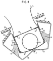
- the Slider elements 40, 42 are located on the partition 30 in the area of Through openings 32, 34. When they swing outwards press the slide plates 36, 38 after the support elements 44, 46 outside, these the swivel plates 24, 26 and thereby the Take part elements 18, 24 of the cover with you. Because of the arrangement the pivot axis C in the region of the bottom of the housing 12 can Submerge sub-elements 18, 20 of the cover under the dashboard. There is therefore no danger of being shot by a vehicle occupant more. It is particularly pointed out that in FIG shown state of the gas bag module, the cover 18, 20 completely is open before the gas bag 14 is pressurized with compressed gas.
- FIG. 3 shows the state of the gas bag module from FIG. 2, after the slide plates 36, 38 under the action of the in Working chamber 52 generated pressure completely to the side walls of the Housing 10 were pivoted out. In this position they have Slide elements 40, 42 the through openings 32, 34 released, so that the compressed gas generated by the gas generator 16 from the working chamber 52 can flow into the gas bag 14 and unfold it.
- Seals 54, 56 provided (see also Figure 4).
- the support element 44, 46 can either be in one piece with the Corresponding pivot plate 24, 26 may be designed, for example with a swivel plate made of plastic as a projection or with a Swivel plate made of metal as a bending projection or as a separate part executed and attached to the swivel plate.
- FIGS. 5 to 7 show a second embodiment of the Airbag module according to the invention shown. Because the construction and the Operation of the gas bag module according to the second embodiment largely correspond to those of the first embodiment only the differences between the two embodiments below received. Components of the second embodiment, the Components with the same function of the first embodiment correspond with the same reference numerals.
- the partition 30 is curved in the second embodiment executed, the center of curvature approximately with the pivot axis C coincides. Furthermore, the slide elements 40, 42 are the same Executed curved, so that there is a flat contact between the slide elements and the partition.
- a sealing element 60, 62 is provided on each support element 40, 42, that in the idle state on the outer wall of the gas generator 16 abuts and together with the support elements 44, 46 and the slide elements 40, 42 forms the working chamber 52.
- each sealing element 60, 62 with a stop 64, 66 provided to limit the pivoting the swivel plates 24, 26 is provided.
- the working chamber is first 52 acted upon by the compressed gas provided by the gas generator 16. Since the slide elements 40, 42 the through openings 32, 34 in the Closing the partition 30 acts on the one prevailing in the chamber 52 Push the support elements 44, 46 outwards, which causes the Cover 18, 20 is opened.
- the gas bag module 10 is shown in the state in which the slide elements 40, 42 the through openings 32, 34 in the partition 30 still close.
- the cover 18, 20 is already fully opened without the gas bag 14 being pressurized with compressed gas becomes.
- the sealing elements 60, 62 close by contact the openings 48, 50, the working chamber 52 in a sealed manner.
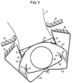
- the gas bag module 10 is in the complete state outwardly pivoted swivel plates 24, 26 and unfolded gas bag 14 shown.
- the stops 64, 66 of the sealing elements 60, 62 engage on lower edge of each opening 48, 50 and thus limits the Swiveling outwards.
- the working chamber 52 is in everyone Position of the pivot plates 24, 26 through the contact of the sealing elements 60, 62 at the bottom of the openings 48, 50 and the System of the slide elements 40, 42 sealed on the partition 30, see above that no pressure loss can occur to the outside.
- FIG. 8 shows an airbag module according to the invention third embodiment shown. Again, just the differences described for the first embodiment of the gas bag module, and the reference numerals used correspond to those from the previous ones Figures known.
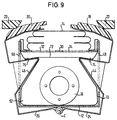
- the working chamber 52 is through a first and a second tissue flap 70, 72 formed around the gas generator 16 are arranged around.
- the first tissue flap 70 extends from the partition 30 along the pivot plate 24, along the support element 44 formed thereon the bottom of the housing 12 and finally along the support element 46 and the swivel plate 26 again towards the partition wall 30.
- the second Fabric flap 72 extends between two fixing points 74, 76, on the swivel plates 24, 26.
- the first fabric tab 70 can be in one piece with the gas bag 14, the partition 30 in the interior of which are arranged and connected to the housing 12 got to.
- the first and second tissue tabs 70, 72 form together a control gas bag, in the interior of which the gas generator 16 is arranged.
- the support elements have one in this embodiment Area on which the tissue flap 70 is supported directly when it is pressurized with compressed gas. This area is formed by the diagonally upwards from the side wall of the housing and towards the center of the Section extending toward the housing of each support element 44, 46.
- the first and the second fabric flap 70, 72 formed working chamber 52 with compressed gas acted upon.
- the first tissue flap 70 is supported on the Support elements 44, 46 and tries to push them out of the housing. Due to the oblique course of the area where the Supporting cloth flaps 70 on each support element results in a type of the wedge action of the fabric part 70 pushing towards the cover the support elements that support opening the cover.
- the swivel plates 24, 26 becomes the sub-elements 18, 20 the cover pivoted under the dashboard 22.
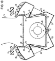
- the gas bag module is fully open Cover 18, 20 and unfolded airbag 14 shown.
- the second Tissue part 72 is always under the action of in working chamber 52 more increasing pressure torn so that the pivot plates 24, 26, driven by the one acting on its support elements 44, 46 Pressure inside the working chamber 52 have been pivoted outwards.
- the openings 48, 50 in the side walls of the Sealed housing 12 by means of the first fabric tab 70, which itself in the upper area of the breakthroughs starting from the connection between the partition 30 and the side walls of the housing to the Fixing points 74, 76 of the pivot plates 24, 26 extends.
- a Escape of the compressed gas provided by the gas generator 16 from the Housing 12 out through the openings 48, 50 is on this Way prevented.
- Figure 11 is a fourth embodiment of an inventive Airbag module shown. Also in this embodiment only the differences from the previously described embodiments explained. The various components are as far they are known from the previous drawings, with the same Reference numerals.
- the gas bag module according to the fourth embodiment is with a one-piece cover 21 provided.
- a single swivel plate 24 used for their swiveling Attachment to the housing 12 is only a single swivel plate 24 used. This is pivotable about a pivot axis C, which in the Middle longitudinal plane of the housing 12 is arranged in the region of the bottom.
- the gas generator 16 is on the right-hand side of FIG Housing arranged, and that formed on the pivot plate 24 and through the opening 48 protruding into the interior of the housing Support element 44 has on its side facing the gas generator 16 a contour adapted to this, the support element 44 also at this embodiment runs obliquely inside the housing, that with the tissue bag 70 pushing towards the gas bag 14 Wedge effect is generated.
- first and a second tissue flap 70, 72 is provided, which together form a Form working chamber 52. After activating the gas generator, this will Working chamber pressurized with gas, and the pivot plate 24 is due to the pressure acting on the support element 44 to the outside panned.
- the cover 21 dips under the dashboard 22 path.
- the gas bag module is shown in a state in which the cover 21 is almost completely open.
- this State is that of the first and second fabric parts 70, 72 Formed working chamber 52 still completed, so that from Gas generator 16 does not provide compressed gas through the through openings 32, 34 flow into the gas bag 14 and unfold it can.
- the second tissue part 72 is torn, and that Pressurized gas can flow through the openings 32, 34 into the gas bag 14 flow in and unfold.
- the first fabric part 70 seals the Breakthrough 48 in the side wall of the housing 12, so that the generated compressed gas completely for filling the gas bag 14 for Available.
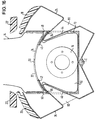
- Figure 14 is a fifth embodiment of an inventive Airbag module shown. Also in this embodiment only the differences from the previously described embodiments explained. The various components are as far they are known from the previous drawings, with the same Reference numerals.
- the gas bag module according to the fifth embodiment is one Provided cloth flap 70, which for sealing at the openings 48, 50 is used, through which the support elements 44, 46 into the Extend inside the housing.
- the support elements 44, 46 are as in the third embodiment with an oblique of the Side walls of the housing 12 in the direction of the gas bag 14 and Center plane of the housing extending support area for the Provide tissue cloth 70.
- stiffening the swivel plates 24, 26 stiffening parts 80, 82 are provided for stiffening the swivel plates.
- Slider elements 40, 42 provided by the gas bag module according to the second embodiment are known. These work with the Partition 30 together, which is also curved.
- the Slider elements 40, 42 are on the upper side of the support elements 44, 46 of the swivel plates 24, 26 by means of a joint 84 or 86 attached. At this joint, the tissue flap 70 is also on the Swivel plates 24, 26 attached.
- the joints can be riveted, Screws, welding spots, etc. in any, to the occurring Loads and materials used trained appropriately be.
- the slide element 42 lies directly on the Partition 30 on while the slide element 40 on the slide element 42 rests on the side facing away from the partition.
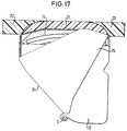
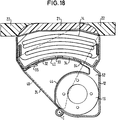
- FIGS. 17 to 20 show a sixth embodiment of the Airbag module shown.
- the components are the same Reference numerals as used in the previous embodiments, and as to the function of these components, reference is made to the above Explanations referenced.
- the sixth embodiment is a combination of second and fourth embodiments. It becomes a single one Swivel plate 24 is used, on which a support element 44 and a Slider element 40 are formed. On the pivot plate 24 is one one-piece cover 21 attached. Furthermore, the Provide swivel plate with a reinforcing part 25 (see especially the side view of Figure 17). To limit the Pivot angle of the pivot plate 24 is a stop nose 65 on Housing 12 used, which in a slot in the support member 44th engages and on a stop 64 formed at the end of the slot can attack. This can be seen in Figure 20, in which the gas bag module with swivel plate 24 pivoted completely outwards and with unfolded airbag 14 is shown.
- the support element is in arranged an area of the housing 12 in which a comparatively large amount Space is available.
- the support elements exercise each time they acted upon by the compressed gas provided by the gas generator be a force on the swivel plates that result in a large Share approximately parallel to the direction of extension of the cover is aligned. In this way, the force is optimal in one Opening movement of the cover implemented.
- This is supported by which improved compared to conventional gas bag modules Leverage ratios when opening the cover.
- the gas bag module acts on the cover to open it Force on the cover with a comparatively small lever arm on. In the gas bag module according to the invention there is a larger one Lever arm available.
Landscapes
- Engineering & Computer Science (AREA)
- Mechanical Engineering (AREA)
- Air Bags (AREA)
Applications Claiming Priority (2)
| Application Number | Priority Date | Filing Date | Title |
|---|---|---|---|
| DE29721644U | 1997-12-08 | ||
| DE29721644U DE29721644U1 (de) | 1997-12-08 | 1997-12-08 | Gassack-Modul für ein Fahrzeuginsassen-Rückhaltesystem |
Publications (3)
| Publication Number | Publication Date |
|---|---|
| EP0921044A2 true EP0921044A2 (fr) | 1999-06-09 |
| EP0921044A3 EP0921044A3 (fr) | 2000-09-27 |
| EP0921044B1 EP0921044B1 (fr) | 2005-03-16 |
Family
ID=8049630
Family Applications (1)
| Application Number | Title | Priority Date | Filing Date |
|---|---|---|---|
| EP98122549A Expired - Lifetime EP0921044B1 (fr) | 1997-12-08 | 1998-12-02 | Module de coussin gonflable pour système de retenue de passager d'un véhicule |
Country Status (5)
| Country | Link |
|---|---|
| US (1) | US6161864A (fr) |
| EP (1) | EP0921044B1 (fr) |
| JP (1) | JPH11240403A (fr) |
| DE (2) | DE29721644U1 (fr) |
| ES (1) | ES2239377T3 (fr) |
Cited By (1)
| Publication number | Priority date | Publication date | Assignee | Title |
|---|---|---|---|---|
| DE10122956B4 (de) * | 2000-05-15 | 2010-11-25 | Trw Inc., Lyndhurst | Airbagmodul |
Families Citing this family (18)
| Publication number | Priority date | Publication date | Assignee | Title |
|---|---|---|---|---|
| US6357785B1 (en) * | 1997-08-12 | 2002-03-19 | Trw Occupant Restraint Systems Gmbh & Co. Kg | Gas bag module for a vehicle occupant restraint system |
| DE29806083U1 (de) * | 1998-04-02 | 1998-07-30 | TRW Occupant Restraint Systems GmbH & Co. KG, 73553 Alfdorf | Gassack-Modul für ein Fahrzeuginsassen-Rückhaltesystem |
| ATE361223T1 (de) * | 1998-05-27 | 2007-05-15 | Volkswagen Ag | Fahrzeugteil mit einer airbagvorrichtung und herstellungsverfahren für ein solches fahrzeugteil |
| DE19846853A1 (de) * | 1998-10-12 | 2000-04-13 | Delphi Automotive Systems Gmbh | Verfahren zum Entfalten eines Luftsacks |
| DE19904328A1 (de) * | 1999-01-28 | 2000-08-03 | Volkswagen Ag | Insassenschutzvorrichtung für ein Kraftfahrzeug mit einem Airbagmodul |
| DE19908135A1 (de) * | 1999-02-25 | 2000-08-31 | Volkswagen Ag | Insassenschutzvorrichtung mit einem Lenkradairbag für ein Kraftfahrzeug |
| DE50010180D1 (de) * | 1999-08-24 | 2005-06-02 | Volkswagen Ag | Airbagvorrichtung mit gesteuerter abdeckeinrichtung |
| DE19958585C1 (de) * | 1999-12-04 | 2001-02-08 | Autoliv Dev | Gassackmodul mit aktiver Öffnung seiner Abdeckung |
| DE19960251A1 (de) * | 1999-12-14 | 2001-06-21 | Takata Europ Gmbh | Luftsackmodul für Kraftfahrzeuge |
| DE50103405D1 (de) * | 2000-04-27 | 2004-09-30 | Volkswagen Ag | Airbagvorrichtung und betriebsverfahren dafür |
| DE50200549D1 (de) * | 2001-02-06 | 2004-08-05 | Volkswagen Ag | Airbagvorrichtung |
| DE10140382A1 (de) * | 2001-08-23 | 2003-03-20 | Sai Automotive Sal Gmbh | Airbagvorrichtung und Verfahren zum Öffnen einer Airbagklappe |
| DE10204333B9 (de) * | 2002-02-01 | 2005-07-21 | Peguform Gmbh & Co. Kg | Rückzugsmechanismus für die Verkleidung eines Airbagsystems |
| FR2900111B1 (fr) * | 2006-04-24 | 2011-02-11 | Trw Automotive Gmbh | Dispositif de retenue d'occupant de vehicule avec coussin a gaz. |
| JP2012176662A (ja) * | 2011-02-25 | 2012-09-13 | Toyoda Gosei Co Ltd | エアバッグドアの位置決め構造 |
| WO2021065778A1 (fr) * | 2019-10-01 | 2021-04-08 | オートリブ ディベロップメント エービー | Module de coussin gonflable de sécurité |
| CN114630771B (zh) * | 2019-11-25 | 2024-01-09 | 奥托立夫开发公司 | 安全气囊模块 |
| EP4079583B1 (fr) * | 2019-12-18 | 2025-05-14 | Autoliv Development AB | Module de coussin de sécurité gonflable |
Family Cites Families (9)
| Publication number | Priority date | Publication date | Assignee | Title |
|---|---|---|---|---|
| US5342085A (en) * | 1990-12-19 | 1994-08-30 | Mazda Motor Corporation | Air bag apparatus for automotive vehicle |
| DE4217173A1 (de) * | 1992-05-23 | 1993-11-25 | Daimler Benz Ag | Rückhaltesystem für Insassen eines Kraftfahrzeuges |
| US5344184A (en) * | 1993-12-21 | 1994-09-06 | Trw Vehicle Safety Systems Inc. | Method and apparatus for restraining a vehicle occupant |
| US5431433A (en) * | 1994-05-02 | 1995-07-11 | Morton International, Inc. | Fastenerless tethered deployment door for passenger-side airbag module |
| KR960037423A (ko) * | 1995-04-25 | 1996-11-19 | 배순훈 | 자동차의 에어백 장치 |
| JP3218966B2 (ja) * | 1996-03-13 | 2001-10-15 | 豊田合成株式会社 | エアバッグ装置を内蔵したガーニッシュ部材 |
| DE19616942B4 (de) * | 1996-04-27 | 2005-06-16 | Mst Automotive Gmbh Automobil-Sicherheitstechnik | Airbag-Abdeckkappe |
| US5722684A (en) * | 1996-06-05 | 1998-03-03 | Morton International, Inc. | Hinged module cover |
| US5941558A (en) * | 1997-06-09 | 1999-08-24 | Textron Automotive Company Inc. | Apparatus for deploying an airbag through a hard panel |
-
1997
- 1997-12-08 DE DE29721644U patent/DE29721644U1/de not_active Expired - Lifetime
-
1998
- 1998-12-02 EP EP98122549A patent/EP0921044B1/fr not_active Expired - Lifetime
- 1998-12-02 DE DE59812658T patent/DE59812658D1/de not_active Expired - Fee Related
- 1998-12-02 ES ES98122549T patent/ES2239377T3/es not_active Expired - Lifetime
- 1998-12-08 JP JP10348963A patent/JPH11240403A/ja active Pending
- 1998-12-08 US US09/206,893 patent/US6161864A/en not_active Expired - Fee Related
Non-Patent Citations (1)
| Title |
|---|
| None |
Cited By (1)
| Publication number | Priority date | Publication date | Assignee | Title |
|---|---|---|---|---|
| DE10122956B4 (de) * | 2000-05-15 | 2010-11-25 | Trw Inc., Lyndhurst | Airbagmodul |
Also Published As
| Publication number | Publication date |
|---|---|
| ES2239377T3 (es) | 2005-09-16 |
| EP0921044B1 (fr) | 2005-03-16 |
| US6161864A (en) | 2000-12-19 |
| JPH11240403A (ja) | 1999-09-07 |
| DE59812658D1 (de) | 2005-04-21 |
| DE29721644U1 (de) | 1998-04-02 |
| EP0921044A3 (fr) | 2000-09-27 |
Similar Documents
| Publication | Publication Date | Title |
|---|---|---|
| EP0921044B1 (fr) | Module de coussin gonflable pour système de retenue de passager d'un véhicule | |
| DE102006017332B3 (de) | Gassack-Einheit | |
| EP1681209B1 (fr) | Dispositif de sac gonflable latéral | |
| EP1855919B1 (fr) | Element tubulaire de conduite d'alimentation en gaz et unite d'alimentation et unite de sac gonflable suspendu | |
| DE19964446B9 (de) | Beifahrersitz-Airbagsystem | |
| EP1391355A2 (fr) | Sac gonflable pour un module de sac de sécurité gonflable | |
| EP1919738B1 (fr) | Dispositif d'airbag pour un véhicule automobile | |
| DE4027996A1 (de) | Luftsacksystem | |
| EP1907242B1 (fr) | Sac gonflable pour systeme de retenue de passagers de vehicule | |
| DE29813082U1 (de) | Gassack-Rückhaltesystem | |
| DE29710745U1 (de) | Knie-Rückhalteeinrichtung für Fahrzeuge | |
| DE102010039895A1 (de) | Airbagmodul für ein Kraftfahrzeug | |
| WO2015107010A1 (fr) | Module de sac gonflable équipé d'un dispositif de commande | |
| DE29922987U1 (de) | Gassack-Modul | |
| DE202005017267U1 (de) | Gassackmodul | |
| EP1251046B1 (fr) | Coussin gonflable | |
| DE29721681U1 (de) | Gassack-Modul für ein Fahrzeuginsassen-Rückhaltesystem | |
| EP1034097A1 (fr) | Dispositif pour influer sur le deploiement du sac gonflable d'un module d'air bag | |
| EP0820908B1 (fr) | Module à coussin gonflable pour un système de retenue d'un passager de véhicule | |
| DE10041763A1 (de) | Airbag-Befestigung | |
| DE10033948A1 (de) | Gassackmodul | |
| EP1737708B1 (fr) | Module d'airbag comportant un generateur de gaz et un sac de gaz | |
| EP1428730A2 (fr) | Système de sécurité pour un véhicule, en particulier pour un véhicule automobile | |
| EP0861759B1 (fr) | Module de sac gonflable côté passager | |
| DE29816905U1 (de) | Gewebeteil zur Anordnung im Inneren eines Gassacks eines Fahrzeuginsassen-Rückhaltesystems |
Legal Events
| Date | Code | Title | Description |
|---|---|---|---|
| PUAI | Public reference made under article 153(3) epc to a published international application that has entered the european phase |
Free format text: ORIGINAL CODE: 0009012 |
|
| AK | Designated contracting states |
Kind code of ref document: A2 Designated state(s): DE ES FR GB IT |
|
| AX | Request for extension of the european patent |
Free format text: AL;LT;LV;MK;RO;SI |
|
| PUAL | Search report despatched |
Free format text: ORIGINAL CODE: 0009013 |
|
| AK | Designated contracting states |
Kind code of ref document: A3 Designated state(s): AT BE CH CY DE DK ES FI FR GB GR IE IT LI LU MC NL PT SE |
|
| AX | Request for extension of the european patent |
Free format text: AL;LT;LV;MK;RO;SI |
|
| 17P | Request for examination filed |
Effective date: 20010214 |
|
| AKX | Designation fees paid |
Free format text: DE ES FR GB IT |
|
| GRAH | Despatch of communication of intention to grant a patent |
Free format text: ORIGINAL CODE: EPIDOS IGRA |
|
| GRAS | Grant fee paid |
Free format text: ORIGINAL CODE: EPIDOSNIGR3 |
|
| 17Q | First examination report despatched |
Effective date: 20031106 |
|
| GRAJ | Information related to disapproval of communication of intention to grant by the applicant or resumption of examination proceedings by the epo deleted |
Free format text: ORIGINAL CODE: EPIDOSDIGR1 |
|
| GRAL | Information related to payment of fee for publishing/printing deleted |
Free format text: ORIGINAL CODE: EPIDOSDIGR3 |
|
| GRAP | Despatch of communication of intention to grant a patent |
Free format text: ORIGINAL CODE: EPIDOSNIGR1 |
|
| RAP1 | Party data changed (applicant data changed or rights of an application transferred) |
Owner name: TRW AUTOMOTIVE GMBH |
|
| GRAS | Grant fee paid |
Free format text: ORIGINAL CODE: EPIDOSNIGR3 |
|
| GRAA | (expected) grant |
Free format text: ORIGINAL CODE: 0009210 |
|
| AK | Designated contracting states |
Kind code of ref document: B1 Designated state(s): DE ES FR GB IT |
|
| PG25 | Lapsed in a contracting state [announced via postgrant information from national office to epo] |
Ref country code: GB Free format text: LAPSE BECAUSE OF FAILURE TO SUBMIT A TRANSLATION OF THE DESCRIPTION OR TO PAY THE FEE WITHIN THE PRESCRIBED TIME-LIMIT Effective date: 20050316 |
|
| REG | Reference to a national code |
Ref country code: GB Ref legal event code: FG4D Free format text: NOT ENGLISH |
|
| REF | Corresponds to: |
Ref document number: 59812658 Country of ref document: DE Date of ref document: 20050421 Kind code of ref document: P |
|
| REG | Reference to a national code |
Ref country code: ES Ref legal event code: FG2A Ref document number: 2239377 Country of ref document: ES Kind code of ref document: T3 |
|
| GBV | Gb: ep patent (uk) treated as always having been void in accordance with gb section 77(7)/1977 [no translation filed] |
Effective date: 20050316 |
|
| PG25 | Lapsed in a contracting state [announced via postgrant information from national office to epo] |
Ref country code: IT Free format text: LAPSE BECAUSE OF NON-PAYMENT OF DUE FEES;WARNING: LAPSES OF ITALIAN PATENTS WITH EFFECTIVE DATE BEFORE 2007 MAY HAVE OCCURRED AT ANY TIME BEFORE 2007. THE CORRECT EFFECTIVE DATE MAY BE DIFFERENT FROM THE ONE RECORDED. Effective date: 20051202 |
|
| PG25 | Lapsed in a contracting state [announced via postgrant information from national office to epo] |
Ref country code: ES Free format text: LAPSE BECAUSE OF NON-PAYMENT OF DUE FEES Effective date: 20051203 |
|
| PGFP | Annual fee paid to national office [announced via postgrant information from national office to epo] |
Ref country code: DE Payment date: 20051230 Year of fee payment: 8 |
|
| PLBE | No opposition filed within time limit |
Free format text: ORIGINAL CODE: 0009261 |
|
| STAA | Information on the status of an ep patent application or granted ep patent |
Free format text: STATUS: NO OPPOSITION FILED WITHIN TIME LIMIT |
|
| ET | Fr: translation filed | ||
| 26N | No opposition filed |
Effective date: 20051219 |
|
| PG25 | Lapsed in a contracting state [announced via postgrant information from national office to epo] |
Ref country code: FR Free format text: LAPSE BECAUSE OF NON-PAYMENT OF DUE FEES Effective date: 20060831 |
|
| REG | Reference to a national code |
Ref country code: FR Ref legal event code: ST Effective date: 20060831 |
|
| REG | Reference to a national code |
Ref country code: ES Ref legal event code: FD2A Effective date: 20051203 |
|
| PG25 | Lapsed in a contracting state [announced via postgrant information from national office to epo] |
Ref country code: DE Free format text: LAPSE BECAUSE OF NON-PAYMENT OF DUE FEES Effective date: 20070703 |