EP0921047B1 - Verfahren zur Bremsflüssigkeitstemperaturbestimmung und Verfahren zur Bremsflüssigkeitsdrücksteuerung - Google Patents
Verfahren zur Bremsflüssigkeitstemperaturbestimmung und Verfahren zur Bremsflüssigkeitsdrücksteuerung Download PDFInfo
- Publication number
- EP0921047B1 EP0921047B1 EP98309827A EP98309827A EP0921047B1 EP 0921047 B1 EP0921047 B1 EP 0921047B1 EP 98309827 A EP98309827 A EP 98309827A EP 98309827 A EP98309827 A EP 98309827A EP 0921047 B1 EP0921047 B1 EP 0921047B1
- Authority
- EP
- European Patent Office
- Prior art keywords
- pressure
- fluid
- brake
- temperature
- brake fluid
- Prior art date
- Legal status (The legal status is an assumption and is not a legal conclusion. Google has not performed a legal analysis and makes no representation as to the accuracy of the status listed.)
- Expired - Lifetime
Links
- 239000012530 fluid Substances 0.000 title claims description 100
- 238000000034 method Methods 0.000 title claims description 21
- 230000006870 function Effects 0.000 description 8
- 238000010586 diagram Methods 0.000 description 5
- 230000004044 response Effects 0.000 description 5
- 230000003247 decreasing effect Effects 0.000 description 2
- 230000007423 decrease Effects 0.000 description 1
- 230000001419 dependent effect Effects 0.000 description 1
- 230000000994 depressogenic effect Effects 0.000 description 1
- 230000004043 responsiveness Effects 0.000 description 1
- 230000035945 sensitivity Effects 0.000 description 1
Images



Classifications
-
- B—PERFORMING OPERATIONS; TRANSPORTING
- B60—VEHICLES IN GENERAL
- B60T—VEHICLE BRAKE CONTROL SYSTEMS OR PARTS THEREOF; BRAKE CONTROL SYSTEMS OR PARTS THEREOF, IN GENERAL; ARRANGEMENT OF BRAKING ELEMENTS ON VEHICLES IN GENERAL; PORTABLE DEVICES FOR PREVENTING UNWANTED MOVEMENT OF VEHICLES; VEHICLE MODIFICATIONS TO FACILITATE COOLING OF BRAKES
- B60T8/00—Arrangements for adjusting wheel-braking force to meet varying vehicular or ground-surface conditions, e.g. limiting or varying distribution of braking force
-
- Y—GENERAL TAGGING OF NEW TECHNOLOGICAL DEVELOPMENTS; GENERAL TAGGING OF CROSS-SECTIONAL TECHNOLOGIES SPANNING OVER SEVERAL SECTIONS OF THE IPC; TECHNICAL SUBJECTS COVERED BY FORMER USPC CROSS-REFERENCE ART COLLECTIONS [XRACs] AND DIGESTS
- Y10—TECHNICAL SUBJECTS COVERED BY FORMER USPC
- Y10S—TECHNICAL SUBJECTS COVERED BY FORMER USPC CROSS-REFERENCE ART COLLECTIONS [XRACs] AND DIGESTS
- Y10S303/00—Fluid-pressure and analogous brake systems
- Y10S303/01—Pressure comparison
-
- Y—GENERAL TAGGING OF NEW TECHNOLOGICAL DEVELOPMENTS; GENERAL TAGGING OF CROSS-SECTIONAL TECHNOLOGIES SPANNING OVER SEVERAL SECTIONS OF THE IPC; TECHNICAL SUBJECTS COVERED BY FORMER USPC CROSS-REFERENCE ART COLLECTIONS [XRACs] AND DIGESTS
- Y10—TECHNICAL SUBJECTS COVERED BY FORMER USPC
- Y10S—TECHNICAL SUBJECTS COVERED BY FORMER USPC CROSS-REFERENCE ART COLLECTIONS [XRACs] AND DIGESTS
- Y10S303/00—Fluid-pressure and analogous brake systems
- Y10S303/02—Brake control by pressure comparison
Definitions
- This invention relates to a method of detecting the temperature of brake fluid which is effective in controlling the brake fluid pressure in an automotive brake using electromagnetic on-off valves or a spool/valve type electromagnetic proportional pressure control valve, and a method of controlling the brake fluid pressure which makes it possible to control the brake fluid pressure to an ideal state while avoiding bad influences due to change in the viscosity of the brake fluid with change in the temperature.
- Recent brake systems include not only ABS's (antilock brake systems) but TCS's (traction control systems) and ASC systems (active safety control systems for correcting oversteering or understeering while the vehicle is turning by individually controlling the wheel brakes).
- a brake system is shown in Fig. 3.
- the fluid passage connecting a master cylinder 2 to a wheel cylinder 4 for producing braking force is open, so that brake fluid can freely flow therebetween.
- an electronic control unit (not shown) detects any lockup tendency of the vehicle wheel and produces a pressure reduction signal, the position of an electromagnetic changeover valve 5 changes over to disconnect the wheel cylinder 4 from the master cylinder 4, while an electromagnetic on-off valve 9 opens to discharge fluid pressure from the wheel cylinder 4 into a reservoir 3.
- the electronic control unit detects this fact and produces a pressure reincrease signal.
- the electromagnetic on-off valves 8 and 9 are opened and closed, respectively, so that fluid pressure is supplied into the wheel cylinder 4 from a pump 6.
- the wheel cylinder pressure thus rises again.
- the electromagnetic on-off valves 8, 9 may be both closed to maintain the wheel cylinder pressure.
- Traction control is similar to antilock control except that the brake pedal 1 is not tredded during traction control. If the electronic control unit detects slip of the vehicle wheel, the electromagnetic changeover valve 5 changes over and the electromagnetic valve 8 opens so that fluid pressure is supplied into the wheel cylinder 4 from an accumulator 7. The wheel cylinder 4 is thus braked in spite of the fact that the brake pedal is not trodden. Then, pressure reduction and pressure reincrease operations are repeated to prevent slip of the vehicle wheel.
- an electromagnetic proportional pressure control valve 10 shown in Fig. 4 is used to introduce fluid pressure from the pump circuit into the wheel cylinder 4 and to discharge fluid pressure from the wheel cylinder 4 into the reservoir 3.
- This electromagnetic proportional pressure control valve 10 comprises a housing 11, a spool 12 substantially liquid-tightly and slidably inserted in the housing, a reaction pin 13 inserted at one end of the spool 12, a spool-biasing spring 14, and an electromagnet 15 for biasing, i.e. pulling, the spool 12 in the direction opposite to the direction in which the spool is biased by the spring 14.
- the housing 11 has a first port 16, a second port 17, a third port 18, a first fluid chamber 19 into which one end of the spool 12 protrudes, and a second fluid chamber 20 into which the other end of the spool 12 protrudes.
- the spool 12 has a surface passage 21, and an internal passage 22 kept in communication with the second port 17.
- the internal passage 22 has one end open to the first fluid passage 19, and at this end, the reaction pin 13 is substantially liquid-tightly inserted in the passage 22.
- a difference equal to the sectional area of the reaction pin 13 is created between the areas for bearing fluid pressures that urges the spool 12 in opposite directions.
- the spool 12 is thus biased under a downward thrust which is equal to the above difference in area multiplied by the pressure at the second port 17.
- a first valve portion 23 is formed to open and shut off communication between the first and second ports 16, 17 according to the position of the spool.
- a second valve portion 24 is formed to open and shut off communication between the second and third ports 17, 18 according to the spool position. The degree of opening of each of the first and second valves 23, 24 changes with the spool position.
- Fpr in the above equation is given by: (P2 - P3) ⁇ S wherein P2 is the pressure at the second port 17 (load pressure), P3 is the reservoir pressure, and S is the sectional area of the reaction pin 13.
- Fsol equals b I2 (b is a constant).
- (Fsp - Fsol) is the spool driving force by the driving means.
- An object of this invention is to provide a method of detecting a brake fluid temperature as a basic data for control without a temperature sensor and a method of controlling brake fluid pressure which can control fluid pressure based on the detected data so that sufficiently accurate control is possible even if the fluid temperature is low and thus its viscosity is extremely high.
- DE-A-19604126 discloses a brake system control method taking account of the temperature of the brake fluid and a brake fluid temperature estimating method not using a temperature sensor.
- a method of detecting brake fluid temperature wherein two pressure sensors are provided for detecting the pressure of a master cylinder in a brake system, one of the pressure sensors has a predetermined zero-point temperature drift function, and the other having no or a minimum amount of zero-point temperature drift, and wherein the temperature of brake fluid with which the pressure sensors are in contact is detected based on a difference in output at zero point between the two pressure sensors.
- Fig. 7 shows the output characteristics at zero point of a pressure sensor I having a zero-point temperature compensation circuit, and the output characteristics at zero point of a pressure sensor II having a temperature drift function.
- Fig. 8 shows a known pressure sensor having a zero-point temperature compensation circuit 32 for producing a signal having a waveform completely opposite to a signal waveform at zero point produced from a sensor element 30 through a sensitivity temperature compensation circuit 31 to keep the output fluctuation to zero.
- This sensor can be used as the pressure sensor I of Fig. 7.
- the pressure sensor II of Fig. 7 may be of the type shown in Fig. 8 in which the zero-point temperature compensation circuit 32 is adjusted such that it has a predetermined drift.
- the pressure sensor output while the brake switch is off that is, while no master cylinder pressure is being produced, drifts with the temperature.
- the pressure sensor output while the brake switch is off that is, while no master cylinder pressure is being produced, drifts with the temperature.
- a temperature sensor may be provided to measure the brake fluid temperature. But it is economically more advantageous to use a pressure sensor and/or a brake switch which are essential elements of the brake system to estimate the temperature based on the zero-point drift output of the pressure sensor.
- the wheel cylinder fluid pressure is controlled by changing over the control mode based on the thus estimated viscosity of the brake fluid to remove any influence due to change in the fluid viscosity.
- the brake fluid pressure is controllable with good responsiveness and control accuracy.
- Fig. 1 shows a brake system to which the method of this invention is applied. This system is constructed by adding means for carrying out the method of this invention to the brake system of Fig. 3.
- This brake system comprises a master cylinder 3, a wheel cylinder 4 for producing a braking force by fluid pressure, an electronic control unit (ECU, not shown), and a fluid pressure control unit comprising an electromagnetic changeover valve 5 activated on command of the ECU, electromagnetic on-off valves 8, 9, a pump 6 and an accumulator 7.
- ECU electronice control unit
- a fluid pressure control unit comprising an electromagnetic changeover valve 5 activated on command of the ECU, electromagnetic on-off valves 8, 9, a pump 6 and an accumulator 7.
- the pressure in the wheel cylinder 4 is increased, reduced and maintained by the electromagnetic on-off valves 8, 9. If the brake fluid used is of a type whose viscosity tends to change widely with temperature, the difference between the target pressure and the actual pressure will widen if the viscosity of the brake fluid becomes extremely high.
- the brake system of this invention has two pressure sensors 25, 26 for detecting the master cylinder pressure.
- the one pressure sensor 25 has a zero-point temperature drift function, while the other sensor 26 has no or a minimum zero-point temperature drift.
- the brake fluid temperature is estimated based on the output difference at zero-point of the two pressure sensors 25, 26. Based on the thus estimated brake fluid temperature, the viscosity of the brake fluid is estimated.
- the electromagnetic on-off valves 8, 9 are controlled according to a control mode corresponding to the fluid viscosity.
- the higher the fluid viscosity the longer the electromagnetic on-off valves 8, 9 are opened.
- the period during which the electromagnetic on-off valves 8, 9 are opened are changed as shown in Fig. 9 such that a required amount of fluid can flow even when the fluid viscosity is extremely high.
- fluid pressure can be increased and decreased within substantially the same range as when the fluid viscosity is low.
- zero point is determined based on the output of the pressure sensor having no or a minimum zero-point temperature drift function.
- the zero point can be determined based on a signal from the brake sensor.
- a single pressure sensor having a zero-point temperature drift function is sufficient. Any output of the pressure sensor produced while the master cylinder is not producing pressure is subject to a temperature drift. Thus, it is possible to estimate the brake fluid temperature based on the output of the pressure sensor which drifts.
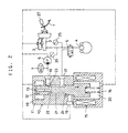
- Fig. 2 shows a system constructed by adding means for carrying out the method of this invention to the brake system of Fig. 4.
- an electromagnetic proportional pressure control valve 10 is used to control the fluid pressure in the wheel cylinder 4.
- the control valve 10 includes a spool 12 having pressure-receiving portions having different sectional areas from each other for receiving the pressure at the second port 17 in opposite directions, and a spool drive means comprising a spring 14 and an electromagnet 15 to which a current controlled by an electronic control unit (not shown) is supplied.
- the spool 12 is adapted to move to a point where the driving force by the drive means balances with the thrust by the pressure at the second port.
- the state of communication between the first port 16 connected to the fluid pressure source or the third port 18 connected to the reservoir 3 and the second port 17 changes over, and the degrees of opening of the first valve portion 23 for opening and shutting off communication between the first port 16 and the second port 17 and the second valve portions 24 for opening and shutting off communication between the second port 17 and the third port 18 are controlled to values corresponding to the current supplied to the electromagnet 15.
- a pressure sensor 25 having a predetermined zero-point temperature drift function and a brake switch 27 are provided.
- the latter serves to detect that the brake pedal 1 is not depressed and thus the master cylinder is not producing pressure.
- the brake fluid temperature is estimated based on the drift output of the pressure sensor 25 at this time, and the viscosity of the brake fluid is estimated based on the thus estimated fluid temperature, and the electromagnetic proportional pressure control valve 10 is controlled according to a control mode based on the fluid viscosity. In this control, as shown in Fig.
- a current supplied to the electromagnet 15 is controlled to carry out overshoot or undershoot control when pressure is increased or decreased, respectively, to a final target pressure equal to the target pressure P(n) plus or minus a predetermined pressure addP, respectively, for time periods T1 or T2.
- value addP and time periods T1, T2 are predetermined to optimal values for every temperature range and stored in the ECU for use in the actual control.
- Time periods during which the electromagnetic on-off valves 8, 9 (Fig.1) are opened, are also predetermined for every temperature range and stored in a memory table so as to be read for use in the actual control.
- the brake system of Fig. 2 may be provided with two pressure sensors 25, 26 to detect the brake fluid pressure based on the output difference at zero point of the two sensors.
- both pressure sensors may have the temperature drift function. In this case, they have to have different output characteristics from each other so that a temperature-dependent output difference is produced.
- the brake fluid temperature is detected based on the outputs of the pressure sensors, no temperature sensor is needed.
- Pressure is controlled according to the control mode corresponding to the brake fluid viscosity estimated based on the detected brake fluid temperature. This solves the problems encountered when the fluid viscosity is extremely high, namely, change in the range within which pressure can be increased and reduced when electromagnetic on-off valves are used, and a delay in response when an electromagnetic proportional control valve is used. This leads to more stable and reliable vehicle behavior control.
Landscapes
- Engineering & Computer Science (AREA)
- Transportation (AREA)
- Mechanical Engineering (AREA)
- Regulating Braking Force (AREA)
- Valves And Accessory Devices For Braking Systems (AREA)
Claims (3)
- Verfahren zum Ermitteln der Bremsflüssigkeitstemperatur, wobei zwei Druckfühler (25, 26) zum Ermitteln des Drucks eines Hauptzylinders (3) in einem Bremssystem vorgesehen sind, von denen ein Druckfühler eine vorgegebene Nullpunkt-Temperaturdriftfunktion hat und der andere keinerlei oder eine minimale Nullpunkt-Temperaturdrift hat, und wobei die Temperatur der Bremsflüssigkeit, mit der die Druckfühler in Kontakt sind, auf der Grundlage einer Ausgangsdifferenz am Nullpunkt zwischen den beiden Druckfühlem ermittelt wird.
- Verfahren zum Ermitteln der Bremsflüssigkeitstemperatur, wobei ein Druckfühler (25) zum Ermitteln des Drucks eines Hauptzylinders in einem Bremssystem und ein Bremsschalter (27) zum Ermitteln des Betriebs einer Bremse vorgesehen sind, wobei der Druckfühler eine vorgegebene Nullpunkt-Temperaturdriftfunktion hat und wobei die Temperatur der Bremsflüssigkeit, mit der der Druckfühler in Kontakt ist, auf der Grundlage des Ausgangswertes am Nullpunkt des Druckfühlers ermittelt wird, wenn der Bremsschalter keinen Bremsbetrieb und folglich keinen Druck im Hauptzylinder feststellt.
- Verfahren zur Bremsflüssigkeits-Druckregelung mit den folgenden Schritten gemäß Verfahren aus Anspruch 1 oder 2: Ermittlung der Temperatur von Bremsflüssigkeit in einem Bremssystem, das einen Radzylinder (4) zum Erzeugen einer Bremskraft mittels Flüssigkeitsdruck, einen Hauptzylinder (3) zum Zuführen von Bremsflüssigkeit zu dem Radzytinder und eine Flüssigkeitsdruck-Regeleinheit zum Regeln des Flüssigkeitsdrucks des Radzylinders aufweist, Einschätzung der Viskosität der Bremsflüssigkeit auf der Grundlage der so ermittelten Temperatur der Bremsflüssigkeit und Regelung des Flüssigkeitsdrucks des Radzylinders in Übereinstimmung mit einem Regelbetrieb entsprechend der geschätzten Flussigkeitsviskosität.
Applications Claiming Priority (2)
| Application Number | Priority Date | Filing Date | Title |
|---|---|---|---|
| JP33280397 | 1997-12-03 | ||
| JP33280397A JP3915209B2 (ja) | 1997-12-03 | 1997-12-03 | ブレーキ液温の検出方法及びブレーキ液圧の制御方法 |
Publications (2)
| Publication Number | Publication Date |
|---|---|
| EP0921047A1 EP0921047A1 (de) | 1999-06-09 |
| EP0921047B1 true EP0921047B1 (de) | 2003-03-12 |
Family
ID=18258984
Family Applications (1)
| Application Number | Title | Priority Date | Filing Date |
|---|---|---|---|
| EP98309827A Expired - Lifetime EP0921047B1 (de) | 1997-12-03 | 1998-12-01 | Verfahren zur Bremsflüssigkeitstemperaturbestimmung und Verfahren zur Bremsflüssigkeitsdrücksteuerung |
Country Status (5)
| Country | Link |
|---|---|
| US (1) | US6203123B1 (de) |
| EP (1) | EP0921047B1 (de) |
| JP (1) | JP3915209B2 (de) |
| CN (1) | CN1225448A (de) |
| DE (1) | DE69812049T2 (de) |
Families Citing this family (21)
| Publication number | Priority date | Publication date | Assignee | Title |
|---|---|---|---|---|
| GB2347981B (en) * | 1999-03-05 | 2003-01-22 | Lucas Industries Ltd | Electro-hydraulic braking systems |
| EP1163134A1 (de) * | 1999-03-17 | 2001-12-19 | Continental Teves AG & Co. oHG | Verfahren zum bestimmen von kenngrössen |
| JP2002539031A (ja) * | 1999-03-17 | 2002-11-19 | コンティネンタル・テーベス・アクチエンゲゼルシヤフト・ウント・コンパニー・オッフェネ・ハンデルスゲゼルシヤフト | パラメータ決定方法 |
| DE19923689A1 (de) * | 1999-05-22 | 2000-11-23 | Bosch Gmbh Robert | Elektrohydraulisches Bremssystem und Verfahren zu seiner Steuerung |
| JP2002293231A (ja) * | 2001-01-23 | 2002-10-09 | Advics:Kk | 車両用液圧制御装置及びそれを用いた車両制動装置 |
| JP4572469B2 (ja) * | 2001-01-23 | 2010-11-04 | 株式会社アドヴィックス | 車両の液圧ブレーキ装置 |
| JP4354334B2 (ja) * | 2004-05-20 | 2009-10-28 | 本田技研工業株式会社 | 筒内圧センサの故障を判定する装置 |
| US20060108869A1 (en) * | 2004-11-19 | 2006-05-25 | Continental Teves, Inc. | Electronic stability system-strategy to improve the stability performance in cold temperatures |
| US7338136B2 (en) * | 2004-12-16 | 2008-03-04 | Honda Motor Co., Ltd. | Electronic braking device |
| US7244003B2 (en) * | 2004-12-20 | 2007-07-17 | International Truck Intellectual Property Company, Llc | Vehicle onboard brake pad/lining wear estimators with temperature estimations |
| JP2006199146A (ja) * | 2005-01-20 | 2006-08-03 | Toyota Motor Corp | ブレーキ液圧制御装置 |
| DE102006022734A1 (de) * | 2005-08-15 | 2007-02-22 | Continental Teves Ag & Co. Ohg | Verfahren und Vorrichtung zum Betrieb einer hydraulischen Fahrzeugbremsanlage |
| DE102005046652A1 (de) * | 2005-09-29 | 2007-04-05 | Robert Bosch Gmbh | Verfahren zum Betreiben eines Bremssystems für Kraftfahrzeuge |
| KR100974721B1 (ko) * | 2007-12-15 | 2010-08-06 | 현대자동차주식회사 | 회생제동 기능을 가진 차량의 브레이크 시스템 |
| US8655567B2 (en) * | 2009-11-09 | 2014-02-18 | Toyota Jidosha Kabushiki Kaisha | Brake control device |
| JP5370391B2 (ja) * | 2011-02-23 | 2013-12-18 | トヨタ自動車株式会社 | 車両用制動装置 |
| JP6003754B2 (ja) * | 2013-03-25 | 2016-10-05 | トヨタ自動車株式会社 | 制動力制御装置 |
| GB2523755B (en) * | 2014-03-03 | 2017-01-11 | Jaguar Land Rover Ltd | Brake fluid temperature monitoring |
| DE102017220308A1 (de) * | 2017-11-15 | 2019-05-16 | Continental Teves Ag & Co. Ohg | Verfahren zum Überprüfen der Funktionalität eines Bremssystems und Bremssystem |
| KR102684920B1 (ko) * | 2019-07-02 | 2024-07-15 | 현대모비스 주식회사 | Esc 통합형 제동 시스템의 제어 방법 |
| US12162453B2 (en) | 2020-10-30 | 2024-12-10 | Westinghouse Air Brake Technologies Corporation | Vehicle braking calibration system |
Family Cites Families (10)
| Publication number | Priority date | Publication date | Assignee | Title |
|---|---|---|---|---|
| JPS58105863A (ja) * | 1981-12-18 | 1983-06-23 | Toyota Motor Corp | 後輪ブレ−キの液圧制御装置 |
| US4881185A (en) * | 1986-04-01 | 1989-11-14 | Chugai Ro. Co., Ltd. | Method of measuring temperature and apparatus for effecting the method |
| US5153823A (en) * | 1989-04-03 | 1992-10-06 | Landis & Gyr Betriebs Ag | Device to measure and/or control flow-through and/or quantity of heat |
| DE4132767C2 (de) * | 1991-10-02 | 1995-09-14 | Daimler Benz Ag | Verfahren zur Diagnose einer elektronisch geregelten Druckmittel-Bremseinrichtung eines Fahrzeuges |
| JPH0858553A (ja) * | 1994-08-26 | 1996-03-05 | Nippondenso Co Ltd | 車両用ブレーキ圧力制御装置 |
| GB9420150D0 (en) | 1994-10-06 | 1994-11-23 | Lucas Ind Plc | Improvements in actuators for vehicle hydraulic braking systems of the brake-by-wire type |
| US5571248A (en) | 1995-03-10 | 1996-11-05 | General Motors Corporation | Pressure regulator |
| DE19513128A1 (de) * | 1995-04-07 | 1996-10-10 | Teves Gmbh Alfred | Verfahren zur temperaturabhängigen Einschaltung einer Druckmittel-Zusatzquelle in schlupfgeregelten Kraftfahrzeug-Bremsanlagen |
| DE19604126A1 (de) * | 1996-02-06 | 1997-08-07 | Bosch Gmbh Robert | Verfahren und Vorrichtung zur Steuerung der Bremsanlage eines Fahrzeugs |
| JPH1035462A (ja) * | 1996-07-29 | 1998-02-10 | Toyota Motor Corp | 車両用加速スリップ制御装置 |
-
1997
- 1997-12-03 JP JP33280397A patent/JP3915209B2/ja not_active Expired - Fee Related
-
1998
- 1998-12-01 EP EP98309827A patent/EP0921047B1/de not_active Expired - Lifetime
- 1998-12-01 DE DE69812049T patent/DE69812049T2/de not_active Expired - Fee Related
- 1998-12-02 CN CN98122999.9A patent/CN1225448A/zh active Pending
- 1998-12-02 US US09/203,329 patent/US6203123B1/en not_active Expired - Fee Related
Also Published As
| Publication number | Publication date |
|---|---|
| DE69812049T2 (de) | 2003-12-24 |
| JP3915209B2 (ja) | 2007-05-16 |
| JPH11165621A (ja) | 1999-06-22 |
| DE69812049D1 (de) | 2003-04-17 |
| US6203123B1 (en) | 2001-03-20 |
| EP0921047A1 (de) | 1999-06-09 |
| CN1225448A (zh) | 1999-08-11 |
Similar Documents
| Publication | Publication Date | Title |
|---|---|---|
| EP0921047B1 (de) | Verfahren zur Bremsflüssigkeitstemperaturbestimmung und Verfahren zur Bremsflüssigkeitsdrücksteuerung | |
| CN101341056B (zh) | 车辆制动系统 | |
| US4824186A (en) | Hydraulic dual-circuit brake system | |
| US5631632A (en) | Pressure monitoring system | |
| US4779935A (en) | Anti-skid apparatus for an automotive vehicle | |
| US5904335A (en) | Flow control valve with a pressure compensation function | |
| US4957330A (en) | Braking device having an automatic fluid pressure regulating function | |
| US5779327A (en) | Pressure supply system having a malfunction detection device | |
| JP2696518B2 (ja) | 制動油圧制御装置 | |
| US6606548B2 (en) | Hydraulic brake pressure controller and method for pressure increase in a wheel brake cylinder | |
| US5733019A (en) | Antilock brake control system for vehicle | |
| US4824185A (en) | Hydraulic dual-circuit braking system | |
| US6247765B1 (en) | Method and apparatus for controlling fluid pressure | |
| US5051907A (en) | Anti-skid control system for an automotive vehicle | |
| EP1431150B1 (de) | Kraftfahrzeugantiblockiersteuerungssystem | |
| US7076357B2 (en) | Vehicle braking control device for braking force distribution | |
| EP1431151B1 (de) | Kraftfahrzeugantiblockiersteuerungssystem | |
| JP3867308B2 (ja) | 液圧制御装置の故障検出方法 | |
| US4930846A (en) | Anti-lock control apparatus | |
| EP0503034B1 (de) | Hydraulische antiblockierbremssysteme für fahrzeuge | |
| EP0963893B1 (de) | Bremsanordnung mit einer Trommelbremsvorrichtung | |
| US5468059A (en) | Hyudraulic anti-lock braking systems for vehicles | |
| JP3146954B2 (ja) | 車輌の制動力制御装置 | |
| US4691969A (en) | Antiskid control system | |
| Feigel et al. | Mechanical Brake Assist-A Potential New Standard Safety Feature |
Legal Events
| Date | Code | Title | Description |
|---|---|---|---|
| PUAI | Public reference made under article 153(3) epc to a published international application that has entered the european phase |
Free format text: ORIGINAL CODE: 0009012 |
|
| AK | Designated contracting states |
Kind code of ref document: A1 Designated state(s): DE FR GB |
|
| AX | Request for extension of the european patent |
Free format text: AL;LT;LV;MK;RO;SI |
|
| 17P | Request for examination filed |
Effective date: 19990816 |
|
| AKX | Designation fees paid |
Free format text: DE FR GB |
|
| 17Q | First examination report despatched |
Effective date: 20020408 |
|
| GRAH | Despatch of communication of intention to grant a patent |
Free format text: ORIGINAL CODE: EPIDOS IGRA |
|
| GRAH | Despatch of communication of intention to grant a patent |
Free format text: ORIGINAL CODE: EPIDOS IGRA |
|
| GRAA | (expected) grant |
Free format text: ORIGINAL CODE: 0009210 |
|
| AK | Designated contracting states |
Designated state(s): DE FR GB |
|
| REG | Reference to a national code |
Ref country code: GB Ref legal event code: FG4D |
|
| REF | Corresponds to: |
Ref document number: 69812049 Country of ref document: DE Date of ref document: 20030417 Kind code of ref document: P |
|
| ET | Fr: translation filed | ||
| PLBE | No opposition filed within time limit |
Free format text: ORIGINAL CODE: 0009261 |
|
| STAA | Information on the status of an ep patent application or granted ep patent |
Free format text: STATUS: NO OPPOSITION FILED WITHIN TIME LIMIT |
|
| 26N | No opposition filed |
Effective date: 20031215 |
|
| REG | Reference to a national code |
Ref country code: GB Ref legal event code: 746 Effective date: 20040728 |
|
| REG | Reference to a national code |
Ref country code: FR Ref legal event code: D6 |
|
| PGFP | Annual fee paid to national office [announced via postgrant information from national office to epo] |
Ref country code: GB Payment date: 20051130 Year of fee payment: 8 |
|
| PGFP | Annual fee paid to national office [announced via postgrant information from national office to epo] |
Ref country code: FR Payment date: 20051208 Year of fee payment: 8 |
|
| GBPC | Gb: european patent ceased through non-payment of renewal fee |
Effective date: 20061201 |
|
| REG | Reference to a national code |
Ref country code: FR Ref legal event code: ST Effective date: 20070831 |
|
| PG25 | Lapsed in a contracting state [announced via postgrant information from national office to epo] |
Ref country code: GB Free format text: LAPSE BECAUSE OF NON-PAYMENT OF DUE FEES Effective date: 20061201 |
|
| PG25 | Lapsed in a contracting state [announced via postgrant information from national office to epo] |
Ref country code: FR Free format text: LAPSE BECAUSE OF NON-PAYMENT OF DUE FEES Effective date: 20070102 |
|
| PGFP | Annual fee paid to national office [announced via postgrant information from national office to epo] |
Ref country code: DE Payment date: 20071129 Year of fee payment: 10 |
|
| PG25 | Lapsed in a contracting state [announced via postgrant information from national office to epo] |
Ref country code: DE Free format text: LAPSE BECAUSE OF NON-PAYMENT OF DUE FEES Effective date: 20090701 |