EP0921048A2 - Dispositif de commande de la pression du fluide de freinage pour véhicules - Google Patents
Dispositif de commande de la pression du fluide de freinage pour véhicules Download PDFInfo
- Publication number
- EP0921048A2 EP0921048A2 EP98123006A EP98123006A EP0921048A2 EP 0921048 A2 EP0921048 A2 EP 0921048A2 EP 98123006 A EP98123006 A EP 98123006A EP 98123006 A EP98123006 A EP 98123006A EP 0921048 A2 EP0921048 A2 EP 0921048A2
- Authority
- EP
- European Patent Office
- Prior art keywords
- terminal
- housing
- electronic control
- male terminal
- control box
- Prior art date
- Legal status (The legal status is an assumption and is not a legal conclusion. Google has not performed a legal analysis and makes no representation as to the accuracy of the status listed.)
- Withdrawn
Links
- 239000012530 fluid Substances 0.000 title claims abstract description 40
- 230000004308 accommodation Effects 0.000 claims abstract description 27
- 238000003780 insertion Methods 0.000 claims description 41
- 230000037431 insertion Effects 0.000 claims description 41
- 239000000758 substrate Substances 0.000 claims description 38
- 238000009413 insulation Methods 0.000 claims description 4
- 238000010276 construction Methods 0.000 description 9
- 230000007423 decrease Effects 0.000 description 6
- 230000003247 decreasing effect Effects 0.000 description 5
- 238000012986 modification Methods 0.000 description 3
- 230000004048 modification Effects 0.000 description 3
- 238000003466 welding Methods 0.000 description 3
- XEEYBQQBJWHFJM-UHFFFAOYSA-N Iron Chemical compound [Fe] XEEYBQQBJWHFJM-UHFFFAOYSA-N 0.000 description 2
- 239000004020 conductor Substances 0.000 description 2
- XLYOFNOQVPJJNP-UHFFFAOYSA-N water Substances O XLYOFNOQVPJJNP-UHFFFAOYSA-N 0.000 description 2
- 238000005452 bending Methods 0.000 description 1
- 238000010586 diagram Methods 0.000 description 1
- 238000007654 immersion Methods 0.000 description 1
- 238000009434 installation Methods 0.000 description 1
- 229910052742 iron Inorganic materials 0.000 description 1
- 239000002184 metal Substances 0.000 description 1
- 229910052751 metal Inorganic materials 0.000 description 1
- 230000010349 pulsation Effects 0.000 description 1
- 238000004080 punching Methods 0.000 description 1
- 238000005476 soldering Methods 0.000 description 1
Images


Classifications
-
- B—PERFORMING OPERATIONS; TRANSPORTING
- B60—VEHICLES IN GENERAL
- B60T—VEHICLE BRAKE CONTROL SYSTEMS OR PARTS THEREOF; BRAKE CONTROL SYSTEMS OR PARTS THEREOF, IN GENERAL; ARRANGEMENT OF BRAKING ELEMENTS ON VEHICLES IN GENERAL; PORTABLE DEVICES FOR PREVENTING UNWANTED MOVEMENT OF VEHICLES; VEHICLE MODIFICATIONS TO FACILITATE COOLING OF BRAKES
- B60T8/00—Arrangements for adjusting wheel-braking force to meet varying vehicular or ground-surface conditions, e.g. limiting or varying distribution of braking force
- B60T8/32—Arrangements for adjusting wheel-braking force to meet varying vehicular or ground-surface conditions, e.g. limiting or varying distribution of braking force responsive to a speed condition, e.g. acceleration or deceleration
- B60T8/34—Arrangements for adjusting wheel-braking force to meet varying vehicular or ground-surface conditions, e.g. limiting or varying distribution of braking force responsive to a speed condition, e.g. acceleration or deceleration having a fluid pressure regulator responsive to a speed condition
- B60T8/36—Arrangements for adjusting wheel-braking force to meet varying vehicular or ground-surface conditions, e.g. limiting or varying distribution of braking force responsive to a speed condition, e.g. acceleration or deceleration having a fluid pressure regulator responsive to a speed condition including a pilot valve responding to an electromagnetic force
- B60T8/3615—Electromagnetic valves specially adapted for anti-lock brake and traction control systems
- B60T8/3675—Electromagnetic valves specially adapted for anti-lock brake and traction control systems integrated in modulator units
- B60T8/368—Electromagnetic valves specially adapted for anti-lock brake and traction control systems integrated in modulator units combined with other mechanical components, e.g. pump units, master cylinders
-
- Y—GENERAL TAGGING OF NEW TECHNOLOGICAL DEVELOPMENTS; GENERAL TAGGING OF CROSS-SECTIONAL TECHNOLOGIES SPANNING OVER SEVERAL SECTIONS OF THE IPC; TECHNICAL SUBJECTS COVERED BY FORMER USPC CROSS-REFERENCE ART COLLECTIONS [XRACs] AND DIGESTS
- Y10—TECHNICAL SUBJECTS COVERED BY FORMER USPC
- Y10S—TECHNICAL SUBJECTS COVERED BY FORMER USPC CROSS-REFERENCE ART COLLECTIONS [XRACs] AND DIGESTS
- Y10S303/00—Fluid-pressure and analogous brake systems
- Y10S303/10—Valve block integrating pump, valves, solenoid, accumulator
Definitions
- the present invention relates to a brake fluid control apparatus for vehicles, which is used for brake fluid pressure control such as antilock brake control and traction control.
- Such kind of brake fluid control apparatus generally has following construction for reducing size, weight and cost. Namely, an electric motor for actuating a pump is mounted on one side of a housing in which devices for fluid pressure control such as the pump and electromagnetic valves are accommodated and passages are formed. Further, on the other side of the housing, an electronic control box provided with a connector for connecting a control circuit board to a battery is mounted.
- the electric motor mounted on one side of the housing and the electronic control box mounted on the other side of the housing need to be electrically connected with each other.
- the electric motor and the electronic control box are electrically connected by lead wires wired out of the housing, size and weight of the apparatus are increased. Further, in this case, since the lead wires need to be connected to the electric motor and the electronic control box by watertight connectors, cost of the apparatus is increased.
- lead wires have flexibility, operation for connection of the wires need to be executed after finishing operation for inserting the lead wires through the through bores. Further due to the same reason, in order to execute the operation for connection, the length of the lead wires is set so that each of them has an extra portion, and space for accommodating the extra portion is necessary. This results in increase of size of the apparatus. Additionally, in the apparatus disclosed in the Japanese National Publication No.7-500068, since the lead wires extending from the electric motor are pulled out from a motor body, it needs that the motor body is provided with a portion for pulling out the lead wires and the connection of lead wires with the pipes is watertight structure, resulting in cost increasing.
- a brake fluid pressure control apparatus as shown in Fig. 9 is disclosed.
- an opening 2a of the case 2 abutting on a housing 3 is closed by a cover 5 made of insulation plastic having a tubular portion 5a inserted in a through bore 3a of the housing 3.
- a conductive member 7 is inserted in the tubular potion 5a.
- the conductive member 7 has a base end connected to a rectifier 6 and a tip end constituting a male terminal 7a.
- the male terminal 7a is engaged and connected with a female terminal 9 in an electronic control box 8.
- the electric motor 1 and the electronic control box 8 can be released from the housing 3 for replacement.
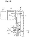
- terminals 12 of devices such as an electromagnetic valve are inserted in through holes 11a of a control circuit substrate 11 accommodated in an electronic control box 8 and soldered to it.
- a male terminal 13b formed at one end of a conductive member 13 having a female terminal 13a (corresponding to the female terminal 9 in Fig. 9) at the other end thereof is inserted in the through hole 11a and welded to the control circuit substrate 11.
- the female terminal 13a is inserted in a terminal accommodation aperture 8b formed in a terminal accommodation portion 8a of the electronic control box 8.
- the thickness of the female terminal 13a is larger than that of the male terminal 13b, insertion direction of the female terminal 13a to the terminal accommodation aperture 8b (indicated by an arrow "A2") is opposed to a direction in which the male terminal 7a of the electric motor is plugged into the female terminal 7b (indicated by an arrow "A1").
- the male terminal 7a is held in the terminal accommodation aperture 8b by engagement of an engagement flap 13c and a step portion 8c of the terminal accommodation aperture 8b. Accordingly, the width "D1" of the terminal accommodation aperture 8b at a portion 8d opposing to the control circuit substrate 11 should be set large for insertion of the female terminal 13a to the terminal accommodation aperture 8b.
- the large width "D1" results in that looseness of the female terminal 13a in a direction indicated by an arrow "B1" is increased and that position of the male terminal 13b with respect to the electronic control box 8 is not determined firmly.
- the terminals 12 of the electromagnetic valves and the male terminal 13b of the conductive member 13 should be simultaneously inserted in the through holes 11a. Therefor, unstable position of the male terminal 13b makes the assembly of the control circuit substrate 11 to the electronic control box 8 considerably difficult.
- the width "D1" of the terminal accommodation aperture 8b at the portion 8d opposing to the control circuit substrate 11 can be set small.
- the female terminal 13a of the conductive member 13 is inserted in the terminal accommodation aperture 8b in the direction as same as the insertion direction of the male terminal 7a indicated by the arrow "A1".
- the female terminal 13a is almost entirely fixed to the terminal accommodating aperture 8b, so that the female terminal 13a hardly moves in the direction indicated by the arrow "B1". Therefor, in this case, engagement of the male terminal 7a of the electric motor with the female terminal 13a is considerably difficult.
- a connector portion 8e for connection to a battery (not shown) provided with the electronic control box 8 is formed so that a corresponding connector 15 can be plugged into it in the same direction as the insertion direction of the male terminal 7a of the electronic control box 8 indicated by the arrow "A1".
- the female terminal 13a of the conductive member 13 is inserted in the direction of the arrow "A1"
- insertion direction of the female terminal 13a is opposing to the insertion direction of the terminal 16a of the connector portion 8e indicated by the arrow "A2".
- the female terminal 13a and the terminal 16a can not be formed integrally as one conductive member. Namely, it is necessary that the terminal 16a is formed at one end of a conductive member and a terminal 16b is formed at the other end thereof. Further, the terminal 16b is connected with the male terminal 13b of the conductive member 13 by means of welding or soldering. This necessity for connecting the male terminal 13b and the terminal 16b increases cost and considerably decreases reliability.
- an object of the invention is to decrease size, weight and cost of a brake fluid pressure control apparatus for vehicles.
- the present invention provides a brake fluid pressure control apparatus for vehicles comprising: a housing accommodating a pump and having through bores which elongate from one side to the other side thereof; an electric motor for actuating the pump mounted on the one side of the housing; an electronic control box mounted on the other side of the housing and having a control circuit which comprises a driving circuit for the electric motor and a connector portion which has terminals for connection to a battery; the electronic control box and the electric motor being connected electrically by conductive members inserted in the through holes; wherein each of the conductive members elongated from the electronic control box and inserted in the through bores has a motor connection male terminal on its tip end, wherein male terminal accommodation portions are provide with the electric motor, in which motor connection male terminals are accommodated, and wherein the motor connection male terminals are plugged in the motor connection female terminal for electrical connection.
- electrical connection between the electric motor and the electronic control box is achieved by engagement between the motor connection female terminal and the motor connection male terminal in easily releasable manner. Therefor, although the assembly of the apparatus is finished, the electric motor and the electronic control box can be easily released for replacement.
- male terminals namely the motor connection male terminals are connected to the electronic control box resulting in needles of clearance.
- the motor connection male terminals can be surely connected to the control circuit in the electronic control box.
- the electronic control box is made of insulation plastic.
- the projections inserted in the through bores are integrally formed on parts of the electronic control box.
- Each conductive member is inserted in an insertion bore formed in each projection. This constriction results in decreasing the total number of parts.
- the projections inserted in the through bores are formed separately to the electronic control box.
- Each conductive member is inserted in the insertion bore formed in each projection.
- the electric motor is provided with brush bases in order to hold brushes for feeding electric current to rectifiers.
- Each brush base is formed with the female terminal accommodation portion.
- Each motor connection female terminal accommodated in the female terminal accommodation portion is electrically connected to the brush. Owing to the terminal accommodation portion provided in the brush base, the total number of parts is decreased
- the brake fluid control apparatus for vehicles further comprises a control circuit substrate provided with the control circuit.
- the connector portion of the electronic control box is positioned outward to the housing and opened toward the other side of the housing on which the electric motor is mounted.
- the conductive member having the motor connection male terminal at one end is provided with a connector male terminal at the other end to form an arch-like configuration.
- the motor connection male terminal is inserted in the insertion bore of the projection and the connector terminal is pressed in the connector portion.
- control circuit is formed on a control circuit substrate.
- the connector portion of the electronic control box is positioned outward to the housing and opened toward the other side of the housing on which the electric motor is mounted.
- a plus conductive member provided with the motor connection terminal at one end is provided with a substrate insertion male terminal at the other end.
- the substrate insertion male terminal is inserted into a through hole formed in the control circuit substrate and soldered to it.
- a minus electric conductive member provided with the motor connection male terminal at one end is provided with a connector terminal at the other end.
- the minus conductive member has an arch-like configuration.
- the motor connection male terminal is inserted in the insertion bore of the projection and the connector male terminal is pressed in the connector portion.
- the pump is a horizontal opposite and reciprocating type plunger pump having two plungers.
- the plunger pump is arranged in the housing so that an axis thereof is parallel to both one side and the other side of the housing.
- the electromagnetic valves are accommodated in accommodation bores bored from the other side toward one side and parallel to the axis taking view from the other side.
- the through holes are formed in regions surrounded by the plunger pump and the electromagnetic valves taking view from the other side of the housing and parallel to the electromagnetic valves. In such construction, an inner space of the housing can be effectively used, resulting in decrease the size of the housing.
- Figs. 1 through 3 show a brake fluid pressure control apparatus 21 according to an embodiment of the invention.
- an electric motor 24 is mounted on one side 22a of the brake fluid pressure control apparatus 21, an electric motor 24 is mounted on the other side 22b opposing to the side 22a.
- an electronic control box 25 is mounted on the other side 22b opposing to the side 22a.
- Fig. 4 shows the electric motor 24 and the housing 22.
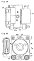
- Figs. 5 through 7 show the electronic control box 25.
- the brake fluid pressure control apparatus 21 is to be interposed between a master cylinder 2 and wheel cylinders 27A, 27B, 27C and 27D.
- a yoke 28 of the electric motor 24 has a flange 28a, which is fixed to the other side 22a of the housing 22 by bolts 29. Further, an opening of the yoke 28 is closed by brash base 30. At a portion where the yoke 28 and the side 22a of the housing 22 abut against each other, a rubber seal member 31 is provide in order to avoid water immersion.
- An output axis 32 of the electric motor 24 is rotatably supported by bearings 33, 34, 35 and 36. At a left end of the output axis 32 inserted in the housing 22 an eccentric portion 32a is provided. Further, on the output axis 32, rectifiers 38 and a core 39 around which coils are wounded are press fitted. The core 39 is opposed to permanent magnets attached to an inner surface of the yoke 28.
- a pair of electric feeding brushes 41, 42 held by the brush base 30 are elastically urged against the rectifiers 38 by springs 43.
- terminal accommodation portions 30a are formed with the brush base 32 near each brush 42.
- a motor connection female terminal 45 constituted by a known tongue-type female terminal is accommodated.
- the motor connection female terminal 45 is connected to the brush 42 by pig-tail wires.
- the female terminal 45 also has an engage finger 45a, which is engaged to a step portion 30c of the terminal accommodation portion 30a to hold the female terminal 45 within the terminal accommodation portion 30a.
- Shape and size of the terminal accommodation portion 30a and the female terminal 45 are set so that the female terminal 45 can move some distance in the directions indicated by an arrow "W" and perpendicular to the figure, namely the female terminal 45 has a backlash.
- elements such as normal open electromagnetic valves 47A, 47B, 47C and 47D, normal close electromagnetic valves 48A, 48B, 48C and 48D, a pair of plunger pumps 49A and 49B, pulsation decreasing rooms 50A and 50B, and reservoirs 51A and 51B are accommodated. Further, in the housing 22, passages communicating the master cylinder 26 with the wheel cylinders 27A-27D through the elements are formed. As shown in Fig. 2, a pair of through bores 53A and 53B communicating the side 22a on which the electric motor 24 is mounted with the other side 22b on which the electronic control box 25 is mounted is formed.
- the plunger pumps 49A and 49B are accommodated in the housing 22 so that axes thereof are parallel to the side 22a on which the electric motor 24 is mounted and the side 22b on which the electronic control box 25 is mounted.
- One ends of the normal open electromagnetic valves 47A-47D and the normal closed electromagnetic valves 48A-48D are inserted in accommodation bores 22d and 22e formed on the other side 22b toward one side 22a.
- the other ends of the normal open electromagnetic valves 47A-47D project from the other side of the housing 22.
- the accommodation bores 22d and 22e are arranged parallel to the axes "L" of the plunger pumps 49A and 49B.
- the through bores 53A and 53B are formed at regions surrounded by the plunger pumps 49A and 49B and the normal open electromagnetic valves 47A-47D (indicated by a symbol "y" in Fig. 4B), and arranged in parallel to both the normal open electromagnetic valves 47A-47D and the normal close electromagnetic valves 48A-48D in case of view from the other side 22b.
- the plunger pumps 49A and 49B are known horizontal opposite and reciprocating type plunger pumps. Each of them are provided with a plunger 55 actuated by the eccentric portion 32a of the output shaft 32 of the electric motor 24.
- an insulation plastic case constituting the electronic control box 25 comprises a main body 57 and a cover 58 detachably attached to the main body 57.
- control circuit substrate 61 is accommodated, on which relays 59 for actuating the electric motor 24, relays for actuating the normal open electromagnetic valves 47A-47D and normal close electromagnetic valves 48A-48D (not shown), and a microcomputer 60 are accommodated.
- Two projections 57a and 57b for electrical connection each having a small diameter cylinder-like shape are projected from the main body 57 of the electronic control box 25 at positions each corresponding to the through bores 53A and 53B of the housing 22.
- an insertion bore 63 is formed in each of the projections 57a and 57b.
- the insertion bore 63 elongates from a tip end of each projection 57a and 57b to an internal cavity of the electronic control box 25.
- the main body 57 of the electronic control box 25 is also provided with a connector portion 57c for connecting the control circuit within the electronic control box 25 with devices such as a battery and various types of sensors (not shown). As shown in Figs. 1 and 2, the connector portion 57c is positioned outward to the housing 22 and opened toward the other side 22a of the housing 22 on which the electric motor is mounted.
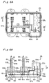
- the electronic control box 25 comprises a plus conductive member 64 and a minus conductive member 65.
- Each of these plus and minus conductive members 64 and 65 is made by punching and bending of a metal plates and bent in band-like configuration.
- the plus conductive member 64 is provided with a base portion 64a accommodated in a positioning groove 57e formed on an inner surface 57d of the main body 57.
- One end of the base portion 64a is bent to form a motor connection male terminal 64b.
- the motor connection male terminal 64b is elongated through the insertion bore 63 of the projection 57a so that the tip end of the motor connection male terminal 64b projects from the tip end of the projection 57a.
- the other end of the base portion 64a is bent toward the inner cavity of the electronic control box 25, namely in a direction opposing to that in which the motor connection male terminal 64b projects to form a substrate insertion male terminal 64c.
- the substrate insertion male terminal 64c is inserted to a through hole 61a of the circuit control substrate 61 and soldered to it.
- a base portion 65a of the minus conductive member 65 arranged in a positioning groove 57f is bent orthogonal to form a motor connection male terminal 65b.
- the motor connection male terminal 65b is elongated through the insertion bore 63 of the projection 57b so that a tip end thereof projects from a tip end of the projection 57b.
- the motor connection male terminal 65 is provided with an engage finger 65d for holding itself in the projection 57.
- the above mentioned motor connection male terminal 64 also has a similar engage finger (not shown).
- the other end of the base portion 65a is bent in the same direction as the motor connection male terminal 65b to form a connector male terminal 65c. This connector male terminal 65c is pressed into the connector portion 57c and to be connected with a plus terminal of the battery (not shown).
- the motor connection male terminal 65b and the connector male terminal 65c are projected in the same direction so that the minus conductive member 65 has an arch-like configuration as shown in Fig. 6B. Owing to such configuration of the minus conductive member 65c, insertion of the male terminal 65b into the insertion bore 57b of the projection 57 and insertion of the male terminal 65c into the connector portion 57c can be executed simultaneously.
- coils 67 of the normal open electromagnetic valves 47A-47D and the normal close electromagnetic valves 48A-48D are over-molded with iron plates 69 for forming magnetic circuits.
- Conductors 68 each connected to the coils 67 are projected into the cavity of the electronic control box 25 and inserted to the through holes 61a to be soldered.
- End portions of the normal open electromagnetic valves 47A-47D and the normal close electromagnetic valves 48A-48D projecting form the side 22b of the housing 22 (shown in Fig. 4A) are each inserted into a concave 67a of each coil 67.
- a conductive member 70 shown in Fig. 6B connects the control circuit substrate 61 with the plus terminal of the battery.
- a connector male terminal 70a formed at one end of the conductive member 70 is pressed into the connector portion 57c so as to be connected to the plus terminal of the battery.
- a substrate insertion male terminal 70b formed at the other end of the conductive member 70 is inserted in the through hole 61a of the control circuit substrate 61 and soldered to it.
- the electronic control box 25 is mounted on the other side of the housing 22.
- the projections 57a and 57b are each inserted through the through bores 53A and 53B so as to elongate from the other side 22b to one side 22a.
- O-rings 71 are outwardly engaged to the projections 57a and 57b for preventing water from entering into the electric motor 24 via through holes 57a and 57b.
- the motor connection male terminals 65b of the minus conductive member 65 is plugged into the motor connection female terminals 45 accommodated in the terminal accommodation portions 30a to achieve electrical connection. Further, the motor connection male terminal 64b of the plus conductive member 64 is plugged into another motor connection female terminal 45 (not shown).
- the plus terminal of the battery and the electric motor 24 are electrically connected through the connector male terminal 70a of the conductive member 70, the substrate insertion male terminal 70b of the conductive member 70, circuits provided on the control circuit substrate 61, the substrate insertion male terminal 64c of the plus conductive member 64, the motor connection male terminal 64c of the plus conductive member 64 and the motor connection female terminal 45.
- the minus terminal of the battery and the electric motor 24 are electrically connected through the connector male terminal 65c of the minus conductive member 65, the motor connection male terminal 65b of the minus conductive member 65 and the motor connection female terminal 45.
- engagement of the motor connection female terminals 45 and the motor connection male terminals 64b and 65b can be released easily since electric connection between the motor connection female terminals 45 and the male terminals 64b and 65b are achieved by plug insertion.
- the electric motor 24 and the electronic control box 25 can be easily released for replacement
- each of the motor connection male terminals 64b and 65b does not need a clearance, namely can be tightly accommodated in the projections 57a and 57b.
- the position of the substrate insertion male terminal 64b of the plus conductive member 64 can be firmly determined.
- the substrate insertion male terminal 64c can be surely inserted in the through hole 61a at the same time of the insertion of the conductors 68 of the normal open electromagnetic vales 47A-47D and normal close electromagnetic valves 48A-48D into the through holes 61a.
- the motor connection female terminals 45 of the electric motor 24 are loosely inserted, the electrical connection between the electronic control box 25 and the electric motor 24 is easily and firmly achieved.
- the electronic control box 25 has the motor connection female terminal 65b differing from the case that the electronic control box has the female terminals (shown in Fig. 12), the motor connection male terminals 65b and the connector male terminal 65c are inserted in the same direction indicated by an arrow "Z".
- the electric motor 24 and the minus terminal of the battery can be connected by one conductive member, namely by the minus conductive member 65 of an arch-like configuration. Accordingly, comparing with the case that two conductive members 13 and 16 are used as shown in Fig. 12, total number of parts is decreased. Cost is also reduced since there is no need to connect two conductive members by means such as welding. Further, owing to that insertion of the motor connection male terminal 65b in the projection 57b and pressing the connector male terminal 65c in the connector portion 57c can be simultaneously executed, the minus conductive member 65 can be easily attached to the electronic control box 25.
- the microcomputer 60 actuates the normal open electromagnetic valves 47A-47D, the normal close electromagnetic valves 48A-48D and the electric motor 24 in order to execute brake fluid pressure control such as antilock control and traction control.
- the projections are preferably integrated to the electronic control box for decreasing the total number of parts as described above, the projections can be formed separately to the electronic control box. Further, the shape of the motor connection female terminals is not limited to the illustrated one as far as the motor connection male terminal can be plugged into it.
Landscapes
- Physics & Mathematics (AREA)
- Electromagnetism (AREA)
- Engineering & Computer Science (AREA)
- Fluid Mechanics (AREA)
- Transportation (AREA)
- Mechanical Engineering (AREA)
- Regulating Braking Force (AREA)
- Valves And Accessory Devices For Braking Systems (AREA)
Applications Claiming Priority (2)
| Application Number | Priority Date | Filing Date | Title |
|---|---|---|---|
| JP33442397 | 1997-12-04 | ||
| JP9334423A JPH11165627A (ja) | 1997-12-04 | 1997-12-04 | 車両用ブレーキ液圧制御装置 |
Publications (2)
| Publication Number | Publication Date |
|---|---|
| EP0921048A2 true EP0921048A2 (fr) | 1999-06-09 |
| EP0921048A3 EP0921048A3 (fr) | 1999-09-01 |
Family
ID=18277220
Family Applications (1)
| Application Number | Title | Priority Date | Filing Date |
|---|---|---|---|
| EP98123006A Withdrawn EP0921048A3 (fr) | 1997-12-04 | 1998-12-04 | Dispositif de commande de la pression du fluide de freinage pour véhicules |
Country Status (3)
| Country | Link |
|---|---|
| US (1) | US6224169B1 (fr) |
| EP (1) | EP0921048A3 (fr) |
| JP (1) | JPH11165627A (fr) |
Cited By (6)
| Publication number | Priority date | Publication date | Assignee | Title |
|---|---|---|---|---|
| WO2001026945A1 (fr) | 1999-10-13 | 2001-04-19 | Robert Bosch Gmbh | Unite electrohydraulique pour la regulation de la pression de freinage d'un systeme de freinage hydraulique de vehicule |
| WO2002060734A1 (fr) * | 2001-02-02 | 2002-08-08 | Continental Teves Ag & Co. Ohg | Organe pour systeme de freinage a regulation electronique |
| EP1353067A1 (fr) * | 1999-10-25 | 2003-10-15 | Continental Teves AG & Co. oHG | Groupe moto-pompe |
| DE102012202224A1 (de) * | 2012-02-14 | 2013-08-14 | Continental Teves Ag & Co. Ohg | Elektrohydraulische Druckregelvorrichtung und Pumpenmotoradapter für Kraftfahrzeugbremssysteme |
| CN104512457A (zh) * | 2013-10-08 | 2015-04-15 | 现代摩比斯株式会社 | Mdps的电源组装置 |
| CN104767323A (zh) * | 2014-01-08 | 2015-07-08 | 大陆汽车系统公司 | 用于将高电流马达连接到车辆的集成电子系统的pcb的柔性连接器系统 |
Families Citing this family (16)
| Publication number | Priority date | Publication date | Assignee | Title |
|---|---|---|---|---|
| EP1068120B1 (fr) * | 1998-03-31 | 2002-07-03 | Continental Teves AG & Co. oHG | Bloc de composants detecteurs de pression |
| DE19958194A1 (de) * | 1999-06-29 | 2001-01-04 | Continental Teves Ag & Co Ohg | Hydraulikaggregat |
| WO2001017832A1 (fr) * | 1999-09-10 | 2001-03-15 | Kelsey-Hayes Company | Unite de commande electro-hydraulique pour systeme de commande de frein electrique |
| JP4563095B2 (ja) * | 2001-04-25 | 2010-10-13 | 日立オートモティブシステムズ株式会社 | ブレーキ液圧制御ユニット |
| WO2004110838A1 (fr) * | 2003-06-14 | 2004-12-23 | Continental Teves Ag & Co. Ohg | Unite hydraulique |
| JP2005088750A (ja) * | 2003-09-17 | 2005-04-07 | Advics:Kk | 液圧制御装置の一体化構造 |
| JP4360877B2 (ja) * | 2003-10-22 | 2009-11-11 | 株式会社日立製作所 | 液圧制御ユニット |
| JP2006027528A (ja) * | 2004-07-20 | 2006-02-02 | Advics:Kk | 車両用ブレーキ液圧制御装置 |
| JP4519619B2 (ja) * | 2004-11-29 | 2010-08-04 | 日立オートモティブシステムズ株式会社 | 液圧制御ユニット |
| DE102005035834A1 (de) * | 2005-05-13 | 2006-11-16 | Continental Teves Ag & Co. Ohg | Elektrohydraulisches Aggregat in verdichteter Bauweise |
| JP5248814B2 (ja) * | 2007-07-18 | 2013-07-31 | 日立オートモティブシステムズ株式会社 | モータ駆動装置およびその検査方法 |
| US20090140572A1 (en) * | 2007-12-04 | 2009-06-04 | Mando Corporation | Pressure sensor |
| JP5161327B2 (ja) * | 2011-02-21 | 2013-03-13 | 日立オートモティブシステムズ株式会社 | ブレーキ制御装置 |
| JP5282126B2 (ja) * | 2011-07-11 | 2013-09-04 | 日信工業株式会社 | モータポンプ装置 |
| JP6092089B2 (ja) * | 2013-12-24 | 2017-03-08 | ミネベアミツミ株式会社 | ブラシ付き直流モータ |
| DE102022207785A1 (de) * | 2022-07-28 | 2024-02-08 | Robert Bosch Gesellschaft mit beschränkter Haftung | Hydraulikblock einer Fremdkraftbremsanlage |
Citations (4)
| Publication number | Priority date | Publication date | Assignee | Title |
|---|---|---|---|---|
| WO1993008050A1 (fr) | 1991-10-12 | 1993-04-29 | Robert Bosch Gmbh | Unite electrohydraulique de regulation de la pression dans des systemes de freinage de vehicules |
| DE4320005A1 (de) | 1993-06-17 | 1995-01-19 | Teves Gmbh Alfred | Elektrische Maschine zur Wandlung von elektrischer und mechanischer Energie, insbesondere radialkraftbeaufschlagter Elektromotor zum Antrieb von Pumpen |
| JPH0811691A (ja) | 1994-06-29 | 1996-01-16 | Aisin Seiki Co Ltd | 車両用ブレーキ液圧制御アクチュエータ |
| JPH0998559A (ja) | 1995-09-29 | 1997-04-08 | Jeco Co Ltd | 直流モータにおけるブラシ配線部構造 |
Family Cites Families (8)
| Publication number | Priority date | Publication date | Assignee | Title |
|---|---|---|---|---|
| DE69308513T2 (de) * | 1992-12-21 | 1997-06-12 | Sumitomo Electric Industries | Antiblockierbremssystem |
| DE59404678D1 (de) | 1993-05-12 | 1998-01-08 | Teves Gmbh Alfred | Elektromotor-pumpen-aggregat |
| US5895207A (en) | 1993-06-17 | 1999-04-20 | Itt Automotive Europe, Gmbh | Electric motor-pump assembly |
| JPH09509383A (ja) | 1994-02-10 | 1997-09-22 | ルーカス・インダストリーズ・パブリック・リミテッド・カンパニー | アンチロックブレーキ装置 |
| US5452948A (en) * | 1994-10-07 | 1995-09-26 | The Whitaker Corporation | Apparatus and method for electronically controlled hydraulic actuator |
| ES2103534T3 (es) | 1994-12-09 | 1997-09-16 | Siemens Ag | Dispositivo de union estanca entre dos lados frontales de una carcasa. |
| US5957547A (en) * | 1996-02-07 | 1999-09-28 | Kelsey-Hayes Company | ABS valve body heat sink for control module electronics |
| US6059381A (en) * | 1997-12-19 | 2000-05-09 | Itt Manufacturing Enterprises, Inc. | ABS pump connector |
-
1997
- 1997-12-04 JP JP9334423A patent/JPH11165627A/ja active Pending
-
1998
- 1998-12-03 US US09/204,290 patent/US6224169B1/en not_active Expired - Lifetime
- 1998-12-04 EP EP98123006A patent/EP0921048A3/fr not_active Withdrawn
Patent Citations (5)
| Publication number | Priority date | Publication date | Assignee | Title |
|---|---|---|---|---|
| WO1993008050A1 (fr) | 1991-10-12 | 1993-04-29 | Robert Bosch Gmbh | Unite electrohydraulique de regulation de la pression dans des systemes de freinage de vehicules |
| JPH07500068A (ja) | 1991-10-12 | 1995-01-05 | ローベルト ボツシユ ゲゼルシヤフト ミツト ベシユレンクテル ハフツング | 自動車のブレーキ装置において圧力調整するための電気液圧式装置 |
| DE4320005A1 (de) | 1993-06-17 | 1995-01-19 | Teves Gmbh Alfred | Elektrische Maschine zur Wandlung von elektrischer und mechanischer Energie, insbesondere radialkraftbeaufschlagter Elektromotor zum Antrieb von Pumpen |
| JPH0811691A (ja) | 1994-06-29 | 1996-01-16 | Aisin Seiki Co Ltd | 車両用ブレーキ液圧制御アクチュエータ |
| JPH0998559A (ja) | 1995-09-29 | 1997-04-08 | Jeco Co Ltd | 直流モータにおけるブラシ配線部構造 |
Cited By (10)
| Publication number | Priority date | Publication date | Assignee | Title |
|---|---|---|---|---|
| WO2001026945A1 (fr) | 1999-10-13 | 2001-04-19 | Robert Bosch Gmbh | Unite electrohydraulique pour la regulation de la pression de freinage d'un systeme de freinage hydraulique de vehicule |
| US6550873B1 (en) | 1999-10-13 | 2003-04-22 | Robert Bosch Gmbh | Electro-hydraulic unit for controlling the breaking pressure in a hydraulic braking system of a vehicle |
| EP1353067A1 (fr) * | 1999-10-25 | 2003-10-15 | Continental Teves AG & Co. oHG | Groupe moto-pompe |
| WO2002060734A1 (fr) * | 2001-02-02 | 2002-08-08 | Continental Teves Ag & Co. Ohg | Organe pour systeme de freinage a regulation electronique |
| DE102012202224A1 (de) * | 2012-02-14 | 2013-08-14 | Continental Teves Ag & Co. Ohg | Elektrohydraulische Druckregelvorrichtung und Pumpenmotoradapter für Kraftfahrzeugbremssysteme |
| CN104512457A (zh) * | 2013-10-08 | 2015-04-15 | 现代摩比斯株式会社 | Mdps的电源组装置 |
| CN104512457B (zh) * | 2013-10-08 | 2017-04-12 | 现代摩比斯株式会社 | Mdps的电源组装置 |
| CN104767323A (zh) * | 2014-01-08 | 2015-07-08 | 大陆汽车系统公司 | 用于将高电流马达连接到车辆的集成电子系统的pcb的柔性连接器系统 |
| US20150194857A1 (en) * | 2014-01-08 | 2015-07-09 | Continental Automotive Systems, Inc. | Flexible connector system for connecting a high current motor to a pcb of an integrated electronics system of a vehicle |
| US10003235B2 (en) | 2014-01-08 | 2018-06-19 | Continental Automotive Systems, Inc. | Flexible connector system for connecting a high current motor to a PCB of an integrated electronics system of a vehicle |
Also Published As
| Publication number | Publication date |
|---|---|
| US6224169B1 (en) | 2001-05-01 |
| JPH11165627A (ja) | 1999-06-22 |
| EP0921048A3 (fr) | 1999-09-01 |
Similar Documents
| Publication | Publication Date | Title |
|---|---|---|
| EP0921048A2 (fr) | Dispositif de commande de la pression du fluide de freinage pour véhicules | |
| US4720078A (en) | Solenoid valve | |
| EP1005109B1 (fr) | Unité de contrôle électronique avec connecteur électrique | |
| CN110447314B (zh) | 电气零部件组装体和车辆用制动液压控制装置 | |
| KR100447899B1 (ko) | 전자밸브 | |
| JPH09296830A (ja) | 電磁連結装置 | |
| EP0544404A2 (fr) | Moteur miniature avec une borne de terre installée | |
| US6731190B2 (en) | Electromagnetic relay | |
| US20100147275A1 (en) | Ignition coil, in particular for an internal combustion engine of a motor vehicle | |
| JP4902438B2 (ja) | 電動モータ | |
| CN102629510A (zh) | 模制线圈及使用模制线圈的电磁阀 | |
| CN110382314B (zh) | 电气零部件组装体和车辆用制动液压控制装置 | |
| US5957548A (en) | Electrohydraulic unit for regulating brake pressure in a motor vehicle brake system | |
| US5692483A (en) | Ignition coil used for an internal combustion engine | |
| US20050088040A1 (en) | Liquid pressure control unit | |
| CN100381700C (zh) | 马达泵机组 | |
| JP2000127934A (ja) | アンチロックブレーキ装置の液圧ユニット | |
| JP2698722B2 (ja) | 電磁弁 | |
| JP2973629B2 (ja) | 油圧ソレノイド | |
| JP2000193123A (ja) | 油圧制御用電磁弁装置 | |
| JP4010622B2 (ja) | 電磁弁 | |
| JP3624557B2 (ja) | 電磁弁の端子構造 | |
| CN118900798A (zh) | 电气零部件组装体、电气零部件组装体的制造方法和车辆用制动器液压控制装置 | |
| KR0123019Y1 (ko) | 전자클러치용 전자석 조립체 | |
| KR100771740B1 (ko) | 자동차의 시동 접촉기용 단자 조립체 |
Legal Events
| Date | Code | Title | Description |
|---|---|---|---|
| PUAI | Public reference made under article 153(3) epc to a published international application that has entered the european phase |
Free format text: ORIGINAL CODE: 0009012 |
|
| AK | Designated contracting states |
Kind code of ref document: A2 Designated state(s): AT BE CH CY DE DK ES FI FR GB GR IE IT LI LU MC NL PT SE |
|
| AX | Request for extension of the european patent |
Free format text: AL;LT;LV;MK;RO;SI |
|
| PUAL | Search report despatched |
Free format text: ORIGINAL CODE: 0009013 |
|
| AK | Designated contracting states |
Kind code of ref document: A3 Designated state(s): AT BE CH CY DE DK ES FI FR GB GR IE IT LI LU MC NL PT SE |
|
| AX | Request for extension of the european patent |
Free format text: AL;LT;LV;MK;RO;SI |
|
| STAA | Information on the status of an ep patent application or granted ep patent |
Free format text: STATUS: THE APPLICATION HAS BEEN WITHDRAWN |
|
| 18W | Application withdrawn |
Withdrawal date: 19991104 |