EP0921067A2 - Propeller, insbesondere Verstellpropeller für Sportboote - Google Patents
Propeller, insbesondere Verstellpropeller für Sportboote Download PDFInfo
- Publication number
- EP0921067A2 EP0921067A2 EP98122723A EP98122723A EP0921067A2 EP 0921067 A2 EP0921067 A2 EP 0921067A2 EP 98122723 A EP98122723 A EP 98122723A EP 98122723 A EP98122723 A EP 98122723A EP 0921067 A2 EP0921067 A2 EP 0921067A2
- Authority
- EP
- European Patent Office
- Prior art keywords
- claws
- blade
- propeller
- projections
- formations
- Prior art date
- Legal status (The legal status is an assumption and is not a legal conclusion. Google has not performed a legal analysis and makes no representation as to the accuracy of the status listed.)
- Withdrawn
Links
- 210000000078 claw Anatomy 0.000 claims abstract description 51
- 230000015572 biosynthetic process Effects 0.000 claims description 30
- 238000005755 formation reaction Methods 0.000 claims description 30
- 230000013011 mating Effects 0.000 claims description 18
- XLYOFNOQVPJJNP-UHFFFAOYSA-N water Substances O XLYOFNOQVPJJNP-UHFFFAOYSA-N 0.000 abstract description 3
- 238000006243 chemical reaction Methods 0.000 description 1
- 238000010276 construction Methods 0.000 description 1
- 238000006073 displacement reaction Methods 0.000 description 1
- 230000037431 insertion Effects 0.000 description 1
- 238000003780 insertion Methods 0.000 description 1
- 238000000926 separation method Methods 0.000 description 1
Images

Classifications
-
- B—PERFORMING OPERATIONS; TRANSPORTING
- B63—SHIPS OR OTHER WATERBORNE VESSELS; RELATED EQUIPMENT
- B63H—MARINE PROPULSION OR STEERING
- B63H3/00—Propeller-blade pitch changing
- B63H3/002—Propeller-blade pitch changing with individually adjustable blades
Definitions
- My present invention relates to a propeller, especially for sport boats and other water craft having an engine. More particularly, the invention relates to a variable-pitch propeller in which the blades are rotatable about radial axes on a hub.
- variable-pitch propellers for motor boats and the like, especially for sport craft, are known.
- Such variable-pitch propellers comprise, as has been described in EP O 231 503, a hub on which a plurality of mounting plates are provided for the respective blades. These mounting plates, for adjustment of the angular positions of the blades about their respective radial axes, are rotated by the blade adjustment mechanism within the hub. The bases of the blades are attached by screws to the respective plates.
- This construction allows the blades to be removed from the hub and replaced, for example, by other blades. In many cases this replacement must be effected under water and where bolting of the base of the blade to the plate is necessary, the bolts can be lost, especially when the last bolt is being released, the blade itself may be lost as it is removed or mounted, and, as a general matter, the operation requires considerable dexterity and can be time-consuming.
- the problem of assembling the blades to the hub can apply to fixed-pitch propellers as well.
- Another object of the invention is to provide a variable-pitch propeller with an improved mounting of the blades to the hub whereby drawbacks of the type described can be avoided.
- Still another object of this invention is to provide a variable-pitch propeller in which the attachment and detachment of individual blades with respect to the adjustment or mounting plates for the blades on the hub can be made more reliable, especially to avoid loss of blades, loss of attachment elements, and to reduce the time required for underwater replacement of the blades.
- each of the adjustment plates on the hub of the variable-pitch propeller so that it has two radial inwardly-directed claws.
- the base or foot of the blade is provided as a circumferential groove in which these claws can engage and the circumferential groove has a plurality of cutaway portions into which the claws can engage to pass into the groove.
- the portions between these cutaway openings of the part of the base defining the groove can be radially-outward flanges or projections which can engage beneath the claws.
- the base of the new blade is fitted onto the plate so that the claws engage in the cutouts and the blade is then rotated through a fraction of a full revolution about its radial axis until the claws engage in the groove and the projections engage beneath the claws.
- Dismounting of the blade can be effected by an angular displacement of the blade relative to the plate in the opposite sense so that the claws and the projections are angularly offset from one another.
- each blade base has a planar underside and the adjustment plate a planar upper side.
- the claws can overhang the planar upper side with a spacing therefrom which corresponds to the thickness of the projections on the base.
- the base and the plate thus are braced flat against one another.
- the circumferential lengths of the claws and the projections may be substantially equal.
- each blade and the respective plate can have a defined relative angular position
- at least one of the claws is advantageously provided with a stop for a corresponding projection of the blade base.
- the latter in mounting of the blade, the latter is rotated until its projection abuts the stop and the blade can then be locked in this angular position.
- a screw or bolt may be used which interconnects the blade base and the plate and is preferably offset from the radial axis of the blade.
- variable-pitch propeller according to the invention can thus comprise:
- the mating formations can have two diametrically opposite claws and projections.
- the claws are on the mounting plate as has been noted and the groove and projections are on the base or foot of the blade.
- a propeller especially for a sport boat and either a variable-pitch propeller or a fixed-pitch propeller, can comprise:
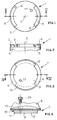
- the blade support plate 1 shown in FIGS. 1 and 2 is rotatably mounted on the usual propeller hub and can be angularly displaced about a radial axis 2 of a variable-pitch propeller.
- the hub usually has at least two such plates and possibly three (see FIGS. 5 and 6) or more, with radial axes thereof being angularly equispaced about the hub axis.
- the hub has been represented at 20
- the hub axis at 21 and the pitch-adjustment mechanism has been shown at 22 within the hub for angularly displacing each of the blades 8 about the respective radial axis 2 to vary the pitch of the propeller.
- each of the blades 1 is planar and provided with two diametrically-opposite claws 4 projecting radially inwardly and extending along the circumference of the respective plate.
- the reference to "radial” is here intended to indicate a relationship to the radial adjustment axis 2.
- each of the claws 4 is provided at one end with an abutment or stop 6.
- each of the blades 8 has a blade foot or base 7 having a planar underside 9 and a circumferential groove extending over the entire periphery.
- the circumferential groove 10 has two radially-opposite cutouts 11 between which the radial projections 12 are disposed. The radius of these projections is somewhat smaller than the radius of the base 7.
- the projections 12 and the cutouts 11, as well as the claws 4 have angular extents of about 90°.
- the width of the gap 5 between the claws and the upper side 3 of the respective plate 1, corresponds to the thickness of the projection 12.
- the base 7 thereof is juxtaposed with its underside 9 with the upper side 3 of a respective plate that the claws 4 engage in the cutouts 11 of the base and thus so that the claws are circumferentially aligned with and are in the plane of the circumferential groove.
- the propeller blade 8 and 6 is rotated about its radial axis 2 so that the claws 4 are engaged in the groove 10 and the projections 12 underlie the claws 4.
- the blade 8 is so rotated until one or both of its projections 12 come to abut a stop 6 both of or the stops 6.
- the blade can be fixed by a screw 25, here an Allen-head screw, which passes through a stepped bore 13 of the base 7 and engages in a threaded bore 14 of the plate 1 aligned therewith. Dismounting of the propeller blade can be effected by the reverse sequence.
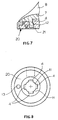
- FIGS. 7 and 8 show an assembly serving as a fixed-pitch propeller and in which the connection between the blade base 7 and a blade support 20 of a propeller without the capacity for pitch adjustment, utilizes a blade support which is rigid with the hub.
- the blade support 20 has a central pin 21 with four radially-outwardly projecting claws 4, located substantially with a 90° offset from one another and between which lie free spaces 11.
- the base 7 of the blade 6 has four inward projections which, upon insertion into the free spaces 11 and rotation of the blade foot through 90°, come to engage below the projections 4 to provide the bayonet connection between the two parts.
- a bolt or pin can be inserted through the aligned bores 13 which are offset from the axis as has previously been described to prevent separation of the bayonet connection until the screw has been removed (see the screw 25 of FIG. 4).
Landscapes
- Engineering & Computer Science (AREA)
- Aviation & Aerospace Engineering (AREA)
- Chemical & Material Sciences (AREA)
- Combustion & Propulsion (AREA)
- Mechanical Engineering (AREA)
- Ocean & Marine Engineering (AREA)
- Structures Of Non-Positive Displacement Pumps (AREA)
- Toys (AREA)
- Hinges (AREA)
Applications Claiming Priority (2)
| Application Number | Priority Date | Filing Date | Title |
|---|---|---|---|
| DE19753927A DE19753927C2 (de) | 1997-12-05 | 1997-12-05 | Verstellpropeller, insbesondere für Sportboote |
| DE19753927 | 1997-12-05 |
Publications (2)
| Publication Number | Publication Date |
|---|---|
| EP0921067A2 true EP0921067A2 (de) | 1999-06-09 |
| EP0921067A3 EP0921067A3 (de) | 2001-10-04 |
Family
ID=7850809
Family Applications (1)
| Application Number | Title | Priority Date | Filing Date |
|---|---|---|---|
| EP98122723A Withdrawn EP0921067A3 (de) | 1997-12-05 | 1998-11-28 | Propeller, insbesondere Verstellpropeller für Sportboote |
Country Status (4)
| Country | Link |
|---|---|
| US (1) | US6142735A (de) |
| EP (1) | EP0921067A3 (de) |
| JP (1) | JPH11227690A (de) |
| DE (1) | DE19753927C2 (de) |
Cited By (2)
| Publication number | Priority date | Publication date | Assignee | Title |
|---|---|---|---|---|
| KR101444151B1 (ko) * | 2012-12-20 | 2014-09-26 | 삼성중공업 주식회사 | 시험용 가변피치 프로펠러 |
| EP2535519A3 (de) * | 2011-06-14 | 2014-11-12 | Rolls-Royce plc | Haltevorrichtung für ein Rotorblatt |
Families Citing this family (2)
| Publication number | Priority date | Publication date | Assignee | Title |
|---|---|---|---|---|
| FR2943312B1 (fr) * | 2009-03-23 | 2011-05-27 | Snecma | Helice non carenee a pales a calage variable pour une turbomachine |
| KR101280476B1 (ko) * | 2011-04-12 | 2013-07-01 | 삼성중공업 주식회사 | 선박용 추진장치 및 이를 구비한 선박 |
Citations (1)
| Publication number | Priority date | Publication date | Assignee | Title |
|---|---|---|---|---|
| EP0231503A1 (de) | 1983-09-22 | 1987-08-12 | Peter Müller | Verstellpropeller für den Antrieb eines Wasserfahrzeugs |
Family Cites Families (8)
| Publication number | Priority date | Publication date | Assignee | Title |
|---|---|---|---|---|
| US12665A (en) * | 1855-04-10 | Improvement sssi steam-boilers | ||
| US821534A (en) * | 1905-06-02 | 1906-05-22 | Frederick L Perkins | Propeller-wheel. |
| FR379387A (fr) * | 1907-06-28 | 1907-11-06 | Claude Nicolas Bonnet | Hélice à pas réglable |
| FR453154A (fr) * | 1913-01-04 | 1913-06-02 | Lucien Chauviere | Système de montage amovible des pales d'hélice sur leur moyeu |
| US4365937A (en) * | 1979-11-26 | 1982-12-28 | Hiebert Harold L | Adjustable pitch propeller drive |
| DD248335A1 (de) * | 1986-04-22 | 1987-08-05 | Rostock Dieselmotoren | Schiffspropeller mit von aussen einstellbaren fluegeln |
| DE19504611A1 (de) * | 1995-02-13 | 1996-08-14 | Dudszus Alfred Prof Dr Ing Hab | Einstellpropeller vereinfachter Bauweise mit Steigungsanpassung an unterschiedliche Vorausfahrt-Propellerleistungen |
| US5871335A (en) * | 1995-10-31 | 1999-02-16 | Siemens Electric Limited | Twist-lock attachment system for a cooling fan and motor |
-
1997
- 1997-12-05 DE DE19753927A patent/DE19753927C2/de not_active Expired - Fee Related
-
1998
- 1998-11-02 US US09/183,958 patent/US6142735A/en not_active Expired - Fee Related
- 1998-11-28 EP EP98122723A patent/EP0921067A3/de not_active Withdrawn
- 1998-12-03 JP JP10344165A patent/JPH11227690A/ja active Pending
Patent Citations (1)
| Publication number | Priority date | Publication date | Assignee | Title |
|---|---|---|---|---|
| EP0231503A1 (de) | 1983-09-22 | 1987-08-12 | Peter Müller | Verstellpropeller für den Antrieb eines Wasserfahrzeugs |
Cited By (3)
| Publication number | Priority date | Publication date | Assignee | Title |
|---|---|---|---|---|
| EP2535519A3 (de) * | 2011-06-14 | 2014-11-12 | Rolls-Royce plc | Haltevorrichtung für ein Rotorblatt |
| US9145776B2 (en) | 2011-06-14 | 2015-09-29 | Rolls-Royce Plc | Retention device for a rotating blade |
| KR101444151B1 (ko) * | 2012-12-20 | 2014-09-26 | 삼성중공업 주식회사 | 시험용 가변피치 프로펠러 |
Also Published As
| Publication number | Publication date |
|---|---|
| DE19753927A1 (de) | 1999-06-17 |
| EP0921067A3 (de) | 2001-10-04 |
| DE19753927C2 (de) | 2000-05-25 |
| US6142735A (en) | 2000-11-07 |
| JPH11227690A (ja) | 1999-08-24 |
Similar Documents
| Publication | Publication Date | Title |
|---|---|---|
| EP1355044B1 (de) | Turbinenschaufel mit abgerundeter Stirnfläche auf dem Schaufelblattfuss | |
| US6739837B2 (en) | Bladed rotor with a tiered blade to hub interface | |
| US9011098B2 (en) | Propeller for an aircraft turbine engine comprising a vane retaining ring mounted about the hub | |
| EP0906216B1 (de) | Auflagerstruktur für einen verankerungsdrehturm und einbauverfahren hierfür | |
| US6142735A (en) | Variable-pitch propeller, especially for sport craft | |
| US7367858B2 (en) | Paddle shaft coupler | |
| EP0360639A1 (de) | Schiffsschraube | |
| US3407779A (en) | Marine bearing | |
| EP1423186B1 (de) | Verfahren zum Montieren eines Rührers | |
| EP0884106B1 (de) | Vorrichtung zur Sicherung auswechselbarer Messer am Messerkopf einer Schneideinrichtung für Fleischschneidemaschinen | |
| US4313391A (en) | Mast shroud system | |
| WO1992008642A1 (en) | Aircraft engine mount adapter | |
| US11952091B2 (en) | Marine vessel propeller, propeller blade and method for installing the marine vessel propeller | |
| US6736601B2 (en) | Impeller for an axial flow fan and a method of mounting a blade on a hub for such fan | |
| US6056609A (en) | Adjustable-pitch propeller, especially for sport boats | |
| US3941222A (en) | Vehicle shoe drum brakes | |
| EP3416884B1 (de) | Klappluftschraube | |
| US3452939A (en) | Rough cast segmental fillings for pulp refiners | |
| CN109625230A (zh) | 船舶轴系锁紧装置 | |
| AU766212B2 (en) | Swivel post latch system for bearing block | |
| US5286116A (en) | Bearing assembly | |
| US10793243B2 (en) | Foldable propeller and method for assembly | |
| GB2146392A (en) | An elastic bearing for a cycloidal propeller | |
| GB2578281A (en) | Blade hub assembly | |
| US3805701A (en) | Printing plate saddle |
Legal Events
| Date | Code | Title | Description |
|---|---|---|---|
| PUAI | Public reference made under article 153(3) epc to a published international application that has entered the european phase |
Free format text: ORIGINAL CODE: 0009012 |
|
| AK | Designated contracting states |
Kind code of ref document: A2 Designated state(s): AT BE CH CY DE DK ES FI FR GB GR IE IT LI LU MC NL PT SE |
|
| AX | Request for extension of the european patent |
Free format text: AL;LT;LV;MK;RO;SI |
|
| RAP1 | Party data changed (applicant data changed or rights of an application transferred) |
Owner name: NASYC HOLDING S.A. |
|
| RIN1 | Information on inventor provided before grant (corrected) |
Inventor name: MUELLER, PETER |
|
| PUAL | Search report despatched |
Free format text: ORIGINAL CODE: 0009013 |
|
| AK | Designated contracting states |
Kind code of ref document: A3 Designated state(s): AT BE CH CY DE DK ES FI FR GB GR IE IT LI LU MC NL PT SE |
|
| AX | Request for extension of the european patent |
Free format text: AL;LT;LV;MK;RO;SI |
|
| AKX | Designation fees paid | ||
| REG | Reference to a national code |
Ref country code: DE Ref legal event code: 8566 |
|
| STAA | Information on the status of an ep patent application or granted ep patent |
Free format text: STATUS: THE APPLICATION IS DEEMED TO BE WITHDRAWN |
|
| 18D | Application deemed to be withdrawn |
Effective date: 20020601 |