EP0921248A2 - Laschenabhänger - Google Patents
Laschenabhänger Download PDFInfo
- Publication number
- EP0921248A2 EP0921248A2 EP98121672A EP98121672A EP0921248A2 EP 0921248 A2 EP0921248 A2 EP 0921248A2 EP 98121672 A EP98121672 A EP 98121672A EP 98121672 A EP98121672 A EP 98121672A EP 0921248 A2 EP0921248 A2 EP 0921248A2
- Authority
- EP
- European Patent Office
- Prior art keywords
- tab
- sheet metal
- hanger according
- metal clamp
- threaded rod
- Prior art date
- Legal status (The legal status is an assumption and is not a legal conclusion. Google has not performed a legal analysis and makes no representation as to the accuracy of the status listed.)
- Granted
Links
- 239000000725 suspension Substances 0.000 title claims abstract description 7
- 239000002184 metal Substances 0.000 claims description 41
- ATJFFYVFTNAWJD-UHFFFAOYSA-N Tin Chemical compound [Sn] ATJFFYVFTNAWJD-UHFFFAOYSA-N 0.000 claims description 7
- 239000011324 bead Substances 0.000 claims description 3
- 230000003014 reinforcing effect Effects 0.000 claims description 2
- 210000002105 tongue Anatomy 0.000 claims description 2
- 238000010276 construction Methods 0.000 description 1
- 230000000694 effects Effects 0.000 description 1
- 230000002787 reinforcement Effects 0.000 description 1
Images


Classifications
-
- E—FIXED CONSTRUCTIONS
- E04—BUILDING
- E04B—GENERAL BUILDING CONSTRUCTIONS; WALLS, e.g. PARTITIONS; ROOFS; FLOORS; CEILINGS; INSULATION OR OTHER PROTECTION OF BUILDINGS
- E04B9/00—Ceilings; Construction of ceilings, e.g. false ceilings; Ceiling construction with regard to insulation
- E04B9/18—Means for suspending the supporting construction
- E04B9/20—Means for suspending the supporting construction adjustable
Definitions
- the invention relates to a hanger for hanging from Profiled beams, consisting of a profiled beam encompassing sheet metal tab, the tab ends together are connected, and one connected to the tab ends Hanger bar.
- Such tab hangers are used, preferably horizontal or approximately horizontal profile beams depend on a bare ceiling or a supporting structure. This requires the two tab ends with each other and with a strap hanger Hanger hanger element, preferably a hanger bar connect.
- a very simple construction is that to screw the two hangers together and that to form the lower end of the hanging bar as a hook reaches through a hole at least one of the tab ends.
- a Height adjustment that may become necessary can be done here but not at the junction between the hanger bar and the tab hanger; therefore it is necessary the hanger bar is adjustable in height at its upper end to record.
- a height adjustment in predetermined steps is possible if instead of the hanger bar a perforated strip made of sheet metal is used or if the tab end has several selectable Has hanging holes. There is a stepless height adjustment not possible here. Even subsequent adjustment A provisional height is only proportionate high workload possible.
- the object of the invention is therefore, a tab hanger Execute the type mentioned so that the connection of the two strap ends and a stepless height adjustment be made possible in a simple manner.
- This task will solved according to the invention in that from one end of the tab a metal clamp is punched out and molded out, which is extends through a window of the other flap end, and that the hanger rod is a threaded rod which is characterized by the Tin clip protrudes and a nut underneath the tin clip wearing.
- the Height adjustment of the bracket depends on turning the nut picked up on the threaded rod, on which there is supports the metal clamp. This height setting can can be changed continuously and sensitively at any time. A unintentional subsequent change in the height setting is due to the mother's self-locking effect already given the threaded rod.
- the sheet metal clamp is preferably essentially in plan U-shaped. Preferably runs in the tab end above and a horizontal cut below the clamp, and the Tin clamp connects two opposite edge strips of the strap end like a bridge. As a result of this permanent connection of the clamp to both The sheet metal clamp also has ends with the tab end Use of relatively thin sheet a high Stability so that it can take high loads.
- one of the two tab ends one bevelled horizontal edge strip, which a Forms an abutment for an upper lock nut.
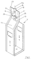
- the tab hanger 1 shown in Fig. 1 serves a Profile carrier 2, in the illustrated embodiment Box profile made of sheet metal, from a (not shown) Height-adjustable bare ceiling or other supporting structure depend.
- the tab hanger 1 has a sheet metal tab 3 (FIG. 2 and 3) which engages around the profile carrier 2, the two Tab ends 4 and 5 joined together are.
- a sheet metal clamp 6 is punched out of one end of the tab 4 and molded out.
- the clamp 6 is in plan in essentially U-shaped. Runs above the clamp 6 a horizontal cut 7 in the tab end 4. A below the plate clamp 6 in the tab end 4 extending horizontally Section 8 forms the edge of a larger opening 9 in Tab end 4.
- the metal clamp 6 connects two opposite Edge strips 4a of the tab end 4 are bridge-like. How to get in Fig. 5 recognizes the two edge strips 4a through Forming the sheet metal tab 6 partially pulled inwards.
- the sheet metal clamp 6 projects through a window (10) of the other flap end 5.
- Threaded rod 11 protrudes through the clamp 6 and carries below the clamp 6 a nut 12 which for Height adjustment on the threaded rod 11 can be rotated.
- the lower end protrudes 11a of the threaded rod 11 through a recess 13 in one the tab end 5 adjoining oblique section 14 of the Sheet metal tab 3.
- One of the two tab ends 4, 5, namely the one shown Embodiment provided with the window 10 Tab end 5, has a folded horizontal Edge strips 15, at least one of the threaded rod 11 has partially receiving notch 16.
- This notch 16 forms a guide for the threaded rod 11.
- the sheet metal tab 3 has two reinforcement beads parallel to the edge 23, which in the illustrated embodiment only in Area of the lower side edges 24 are interrupted to when folding the sheet metal tab 3 an exact adjustment to allow the predetermined width of the profile beam 2. Due to the reinforcing beads 23 parallel to the edge, also at Using relatively thin sheet metal is a tab suspension high rigidity and load capacity achieved.
Landscapes
- Engineering & Computer Science (AREA)
- Architecture (AREA)
- Physics & Mathematics (AREA)
- Electromagnetism (AREA)
- Civil Engineering (AREA)
- Structural Engineering (AREA)
- Holders For Apparel And Elements Relating To Apparel (AREA)
- Load-Engaging Elements For Cranes (AREA)
- Joining Of Building Structures In Genera (AREA)
- Clamps And Clips (AREA)
Abstract
Description
Claims (11)
- Laschenabhänger (1) zum Abhängen von Profilträgern (2), bestehend aus einer den Profilträger (2) umgreifenden Blechlasche (3), deren Laschenenden (4,5;4',5') miteinander verbunden sind, und einem mit den Laschenenden (4,5;4',5') verbundenen Abhängerstab (11), dadurch gekennzeichnet, daß aus dem einen Laschenende (4,4') eine Blechschelle (6) ausgestanzt und herausgeformt ist, die sich durch ein Fenster (10) des anderen Laschenendes (5,5') erstreckt, und daß der Abhängerstab ein Gewindestab (11) ist, der durch die Blechschelle (6) ragt und unterhalb der Blechschelle (6) eine Mutter (12) trägt.
- Laschenabhänger nach Anspruch 1, dadurch gekennzeichnet, daß die Blechschelle (6) im Grundriß im wesentlichen U-förmig ist.
- Laschenabhänger nach Anspruch 2, dadurch gekennzeichnet, daß im Laschenende (4,4') oberhalb und unterhalb der Blechschelle (6) ein horizontaler Schnitt (7 bzw. 8) verläuft und daß die Blechschelle (6) ein horizontaler Schnitt (7 bzw. 8) verläuft und daß die Blechschelle (6) zwei gegenüberliegende Randstreifen (4a) des Laschenendes (4,4') brückenartig verbindet.
- Laschenende nach Anspruch 1, dadurch gekennzeichnet, daß eines der beiden Laschenenden (4 bzw. 5) einen abgekanteten horizontalen Randstreifen (15) aufweist, der ein Widerlager für eine obere Kontermutter (17) bildet.
- Laschenabhänger nach Anspruch 4, dadurch gekennzeichnet, daß der Randstreifen (15) in der gleichen Richtung abgekantet ist, in der sich die Blechschelle (6) erstreckt.
- Laschenabhänger nach Anspruch 5, dadurch gekennzeichnet, daß der Randstreifen (15) eine den Gewindestab (11) mindestens teilweise aufnehmende Einkerbung (16) aufweist.
- Laschenabhänger nach Anspruch 1, dadurch gekennzeichnet, daß aus den beiden beiderseitig des Profilträgers (2) angeordneten vertikalen Abschnitten (18) der Blechlasche (3) nach innen faltbare Haltezungen (21) ausgestanzt sind.
- Laschenabhänger nach Anspruch 1, dadurch gekennzeichnet, daß die Blechlasche (3) zwei randparallele Verstärkungssicken (23) aufweist.
- Laschenabhänger nach Anspruch 1, dadurch gekennzeichnet, daß das untere Ende (11a) des Gewindestabes (11) durch eine Aussparung (13) in einem an das Laschenende (5) anschließenden schrägen Abschnitt (14) der Blechlasche (3) ragt.
- Laschenabhänger nach Anspruch 1, dadurch gekennzeichnet, daß die Längsachse (11b) des Gewindestabs (11) angenähert in der Verbindungsebene (23) der beiden Laschenenden (4', 5') liegt und beide Laschenenden (4', 5') oberhalb und unterhalb der Blechschelle (6) bzw. des Fensters (10) entgegengesetzt zur Blechschelle (6) gerichtete Auswölbungen (24, 25) aufweisen.
- Laschenabhänger nach einem der Ansprüche 1-10, dadurch gekennzeichnet, daß unmittelbar unter der Blechschelle (6) an beiden Laschenenden (4', 5') eine die Mutter (12) aufnehmende Aussparung (26) vorgesehen ist.
Applications Claiming Priority (2)
| Application Number | Priority Date | Filing Date | Title |
|---|---|---|---|
| DE29721485U | 1997-12-05 | ||
| DE29721485U DE29721485U1 (de) | 1997-12-05 | 1997-12-05 | Laschenabhänger |
Publications (3)
| Publication Number | Publication Date |
|---|---|
| EP0921248A2 true EP0921248A2 (de) | 1999-06-09 |
| EP0921248A3 EP0921248A3 (de) | 1999-06-30 |
| EP0921248B1 EP0921248B1 (de) | 2003-03-26 |
Family
ID=8049514
Family Applications (1)
| Application Number | Title | Priority Date | Filing Date |
|---|---|---|---|
| EP98121672A Expired - Lifetime EP0921248B1 (de) | 1997-12-05 | 1998-11-13 | Laschenabhänger |
Country Status (5)
| Country | Link |
|---|---|
| EP (1) | EP0921248B1 (de) |
| AT (1) | ATE235619T1 (de) |
| DE (2) | DE29721485U1 (de) |
| ES (1) | ES2195257T3 (de) |
| WO (1) | WO1999029981A1 (de) |
Cited By (1)
| Publication number | Priority date | Publication date | Assignee | Title |
|---|---|---|---|---|
| KR20040039927A (ko) * | 2002-11-05 | 2004-05-12 | 주식회사 협신건영 | 천정구조물용 방진행거 |
Families Citing this family (7)
| Publication number | Priority date | Publication date | Assignee | Title |
|---|---|---|---|---|
| DE69936806T2 (de) | 1998-03-26 | 2008-04-30 | Mitsubishi Denki K.K. | Spreizspektrumnachrichtenübertragungsverfahren |
| KR20080072203A (ko) * | 2007-02-01 | 2008-08-06 | 복진홍 | 천장자재 지지용 행거 |
| EP2416042B1 (de) | 2010-08-03 | 2014-01-01 | Zurecon AG | Justierbare Aufhängevorrichtung |
| JP6258155B2 (ja) * | 2014-08-22 | 2018-01-10 | 常盤工業株式会社 | 吊り天井構造とその金具 |
| CA3064208A1 (en) * | 2018-12-12 | 2020-06-12 | Andrew Cook | Clip hanger and ceiling suspension system incorporating same |
| KR102470244B1 (ko) * | 2020-04-22 | 2022-11-23 | 정민시 | 천장 경량철골 구조 메인 캐리어의 장착수단 |
| GB2605237A (en) * | 2020-11-30 | 2022-09-28 | Gripple Ltd | Bracing assembly and support system |
Family Cites Families (7)
| Publication number | Priority date | Publication date | Assignee | Title |
|---|---|---|---|---|
| BE638926A (de) * | ||||
| FR1482530A (fr) * | 1965-06-15 | 1967-05-26 | United Lighting & Ceiling Co | Panneau modulaire cloisonné pour plafonds lumineux |
| EP0057454B1 (de) * | 1981-01-30 | 1985-09-04 | Gutermuth, Paul, sen. | Höhenverstellbare Aufhängevorrichtung |
| FR2589907B1 (fr) * | 1985-11-07 | 1988-08-12 | Placoplatre Sa | Suspente pour faux-plafond. |
| DE8902613U1 (de) * | 1989-03-04 | 1989-04-27 | Wichert, Hans-Rainer, 5880 Lüdenscheid | Abhänger für die Befestigung einer Zwischendecke |
| FR2690180B1 (fr) * | 1992-04-17 | 1994-07-08 | Lafarge Platres | Dispositifs de liaison entre des fourrures se croisant orthogonalement et de suspension de l'ossature formee par les fourrures associees. |
| DE29700387U1 (de) * | 1997-01-09 | 1997-05-15 | Richter-System GmbH & Co KG, 64347 Griesheim | Abhänger |
-
1997
- 1997-12-05 DE DE29721485U patent/DE29721485U1/de not_active Expired - Lifetime
-
1998
- 1998-11-13 DE DE59807635T patent/DE59807635D1/de not_active Expired - Lifetime
- 1998-11-13 AT AT98121672T patent/ATE235619T1/de active
- 1998-11-13 ES ES98121672T patent/ES2195257T3/es not_active Expired - Lifetime
- 1998-11-13 EP EP98121672A patent/EP0921248B1/de not_active Expired - Lifetime
- 1998-11-26 WO PCT/EP1998/007648 patent/WO1999029981A1/de not_active Ceased
Non-Patent Citations (1)
| Title |
|---|
| None |
Cited By (1)
| Publication number | Priority date | Publication date | Assignee | Title |
|---|---|---|---|---|
| KR20040039927A (ko) * | 2002-11-05 | 2004-05-12 | 주식회사 협신건영 | 천정구조물용 방진행거 |
Also Published As
| Publication number | Publication date |
|---|---|
| ATE235619T1 (de) | 2003-04-15 |
| WO1999029981A1 (de) | 1999-06-17 |
| DE29721485U1 (de) | 1998-01-29 |
| ES2195257T3 (es) | 2003-12-01 |
| DE59807635D1 (de) | 2003-04-30 |
| EP0921248A3 (de) | 1999-06-30 |
| EP0921248B1 (de) | 2003-03-26 |
Similar Documents
| Publication | Publication Date | Title |
|---|---|---|
| DE60103348T2 (de) | Schwenkbares Deckenpanel | |
| DE69514817T2 (de) | Tragvorrichtung für abgehängte decken | |
| EP3896239A1 (de) | Baugerüst | |
| EP0921248B1 (de) | Laschenabhänger | |
| DE2412381C3 (de) | Befestigungsanordnung für Begrenzungstafeln in Form eines Gitters | |
| EP1136632A1 (de) | Halter für mindestens eine Glastafel einer Glasfasade | |
| EP0518193B1 (de) | Halter für Balkonblumenkästen | |
| DE3005315A1 (de) | Befestigungsteil zur befestigung eines horizontal erstreckten tragelementes einer fassadenkonstruktion an einer senkrechten wand | |
| EP0049431B1 (de) | Rasterdecke | |
| EP0716198A2 (de) | Vorrichtung zum Befestigen von Fassadenplatten | |
| CH674392A5 (de) | ||
| DE3517306C2 (de) | ||
| EP1201841A1 (de) | Direktabhänger für C-Schienen | |
| EP2236687A1 (de) | Knotenabhänger für ein abgehängtes Deckensystem | |
| DE102018203080B4 (de) | Fundamentsystem für die lagerung von flächig nebeneinander angeordneten solarpaneelen | |
| DE202005005831U1 (de) | Neigungseinstellbare Aufstiegshilfe | |
| DE3523741C2 (de) | Tragkonstruktion für abgehängte Decken | |
| EP0761904A1 (de) | Montagesystem für Platten | |
| EP1001112B1 (de) | Gerüst für eine Schalung zur Herstellung einer Voute | |
| EP1165902A1 (de) | Satz von konstruktionselementen zur bildung einer gitterförmigen tragstruktur | |
| DE2615894A1 (de) | Bausatz zur verbindung von tragprofilen einer unterdecke | |
| EP0897040A1 (de) | Aufhängevorrichtung für Unterdecken | |
| DE3038022A1 (de) | Aufhaengbare rasterdecke | |
| DE2733448C3 (de) | Hängedecke | |
| EP0465904A1 (de) | Deckenverkleidung |
Legal Events
| Date | Code | Title | Description |
|---|---|---|---|
| PUAI | Public reference made under article 153(3) epc to a published international application that has entered the european phase |
Free format text: ORIGINAL CODE: 0009012 |
|
| PUAL | Search report despatched |
Free format text: ORIGINAL CODE: 0009013 |
|
| AK | Designated contracting states |
Kind code of ref document: A2 Designated state(s): AT BE CH CY DE DK ES FI FR GB GR IE IT LI LU MC NL PT SE |
|
| AX | Request for extension of the european patent |
Free format text: AL;LT;LV;MK;RO;SI |
|
| AK | Designated contracting states |
Kind code of ref document: A3 Designated state(s): AT BE CH CY DE DK ES FI FR GB GR IE IT LI LU MC NL PT SE |
|
| AX | Request for extension of the european patent |
Free format text: AL;LT;LV;MK;RO;SI |
|
| 17P | Request for examination filed |
Effective date: 19990915 |
|
| AKX | Designation fees paid |
Free format text: AT BE CH CY DE DK ES FI FR GB GR IE IT LI LU MC NL PT SE |
|
| GRAH | Despatch of communication of intention to grant a patent |
Free format text: ORIGINAL CODE: EPIDOS IGRA |
|
| GRAH | Despatch of communication of intention to grant a patent |
Free format text: ORIGINAL CODE: EPIDOS IGRA |
|
| GRAA | (expected) grant |
Free format text: ORIGINAL CODE: 0009210 |
|
| AK | Designated contracting states |
Designated state(s): AT BE CH CY DE DK ES FI FR GB GR IE IT LI LU MC NL PT SE |
|
| PG25 | Lapsed in a contracting state [announced via postgrant information from national office to epo] |
Ref country code: IE Free format text: LAPSE BECAUSE OF NON-PAYMENT OF DUE FEES Effective date: 20030326 Ref country code: FI Free format text: LAPSE BECAUSE OF FAILURE TO SUBMIT A TRANSLATION OF THE DESCRIPTION OR TO PAY THE FEE WITHIN THE PRESCRIBED TIME-LIMIT Effective date: 20030326 |
|
| REG | Reference to a national code |
Ref country code: GB Ref legal event code: FG4D Free format text: NOT ENGLISH |
|
| REG | Reference to a national code |
Ref country code: CH Ref legal event code: EP |
|
| REF | Corresponds to: |
Ref document number: 59807635 Country of ref document: DE Date of ref document: 20030430 Kind code of ref document: P |
|
| REG | Reference to a national code |
Ref country code: IE Ref legal event code: FG4D Free format text: GERMAN |
|
| GBT | Gb: translation of ep patent filed (gb section 77(6)(a)/1977) | ||
| PG25 | Lapsed in a contracting state [announced via postgrant information from national office to epo] |
Ref country code: SE Free format text: LAPSE BECAUSE OF FAILURE TO SUBMIT A TRANSLATION OF THE DESCRIPTION OR TO PAY THE FEE WITHIN THE PRESCRIBED TIME-LIMIT Effective date: 20030626 Ref country code: PT Free format text: LAPSE BECAUSE OF FAILURE TO SUBMIT A TRANSLATION OF THE DESCRIPTION OR TO PAY THE FEE WITHIN THE PRESCRIBED TIME-LIMIT Effective date: 20030626 Ref country code: DK Free format text: LAPSE BECAUSE OF FAILURE TO SUBMIT A TRANSLATION OF THE DESCRIPTION OR TO PAY THE FEE WITHIN THE PRESCRIBED TIME-LIMIT Effective date: 20030626 |
|
| REG | Reference to a national code |
Ref country code: GR Ref legal event code: EP Ref document number: 20030402230 Country of ref document: GR |
|
| PG25 | Lapsed in a contracting state [announced via postgrant information from national office to epo] |
Ref country code: LU Free format text: LAPSE BECAUSE OF NON-PAYMENT OF DUE FEES Effective date: 20031113 Ref country code: CY Free format text: LAPSE BECAUSE OF FAILURE TO SUBMIT A TRANSLATION OF THE DESCRIPTION OR TO PAY THE FEE WITHIN THE PRESCRIBED TIME-LIMIT Effective date: 20031113 |
|
| REG | Reference to a national code |
Ref country code: IE Ref legal event code: FD4D Ref document number: 0921248E Country of ref document: IE |
|
| PG25 | Lapsed in a contracting state [announced via postgrant information from national office to epo] |
Ref country code: MC Free format text: LAPSE BECAUSE OF NON-PAYMENT OF DUE FEES Effective date: 20031130 Ref country code: LI Free format text: LAPSE BECAUSE OF NON-PAYMENT OF DUE FEES Effective date: 20031130 Ref country code: CH Free format text: LAPSE BECAUSE OF NON-PAYMENT OF DUE FEES Effective date: 20031130 Ref country code: BE Free format text: LAPSE BECAUSE OF NON-PAYMENT OF DUE FEES Effective date: 20031130 |
|
| ET | Fr: translation filed | ||
| PLBE | No opposition filed within time limit |
Free format text: ORIGINAL CODE: 0009261 |
|
| STAA | Information on the status of an ep patent application or granted ep patent |
Free format text: STATUS: NO OPPOSITION FILED WITHIN TIME LIMIT |
|
| 26N | No opposition filed |
Effective date: 20031230 |
|
| BERE | Be: lapsed |
Owner name: *RICHTER-SYSTEM G.M.B.H. & CO. K.G. Effective date: 20031130 |
|
| PG25 | Lapsed in a contracting state [announced via postgrant information from national office to epo] |
Ref country code: NL Free format text: LAPSE BECAUSE OF NON-PAYMENT OF DUE FEES Effective date: 20040601 |
|
| REG | Reference to a national code |
Ref country code: CH Ref legal event code: PL |
|
| NLV4 | Nl: lapsed or anulled due to non-payment of the annual fee |
Effective date: 20040601 |
|
| PGFP | Annual fee paid to national office [announced via postgrant information from national office to epo] |
Ref country code: GB Payment date: 20131122 Year of fee payment: 16 Ref country code: FR Payment date: 20131119 Year of fee payment: 16 Ref country code: AT Payment date: 20131128 Year of fee payment: 16 Ref country code: DE Payment date: 20130830 Year of fee payment: 16 |
|
| PGFP | Annual fee paid to national office [announced via postgrant information from national office to epo] |
Ref country code: IT Payment date: 20131125 Year of fee payment: 16 Ref country code: ES Payment date: 20131120 Year of fee payment: 16 Ref country code: GR Payment date: 20131126 Year of fee payment: 16 |
|
| REG | Reference to a national code |
Ref country code: DE Ref legal event code: R119 Ref document number: 59807635 Country of ref document: DE |
|
| REG | Reference to a national code |
Ref country code: AT Ref legal event code: MM01 Ref document number: 235619 Country of ref document: AT Kind code of ref document: T Effective date: 20141113 |
|
| GBPC | Gb: european patent ceased through non-payment of renewal fee |
Effective date: 20141113 |
|
| REG | Reference to a national code |
Ref country code: GR Ref legal event code: ML Ref document number: 20030402230 Country of ref document: GR Effective date: 20150604 |
|
| REG | Reference to a national code |
Ref country code: FR Ref legal event code: ST Effective date: 20150731 |
|
| PG25 | Lapsed in a contracting state [announced via postgrant information from national office to epo] |
Ref country code: AT Free format text: LAPSE BECAUSE OF NON-PAYMENT OF DUE FEES Effective date: 20141113 Ref country code: GR Free format text: LAPSE BECAUSE OF NON-PAYMENT OF DUE FEES Effective date: 20150604 |
|
| PG25 | Lapsed in a contracting state [announced via postgrant information from national office to epo] |
Ref country code: GB Free format text: LAPSE BECAUSE OF NON-PAYMENT OF DUE FEES Effective date: 20141113 Ref country code: DE Free format text: LAPSE BECAUSE OF NON-PAYMENT OF DUE FEES Effective date: 20150602 |
|
| PG25 | Lapsed in a contracting state [announced via postgrant information from national office to epo] |
Ref country code: FR Free format text: LAPSE BECAUSE OF NON-PAYMENT OF DUE FEES Effective date: 20141201 |
|
| REG | Reference to a national code |
Ref country code: ES Ref legal event code: FD2A Effective date: 20151230 |
|
| PG25 | Lapsed in a contracting state [announced via postgrant information from national office to epo] |
Ref country code: IT Free format text: LAPSE BECAUSE OF NON-PAYMENT OF DUE FEES Effective date: 20141113 |
|
| PG25 | Lapsed in a contracting state [announced via postgrant information from national office to epo] |
Ref country code: ES Free format text: LAPSE BECAUSE OF NON-PAYMENT OF DUE FEES Effective date: 20141114 |