EP0921308A2 - Turbine hydraulique installée submergée dans un barrage - Google Patents
Turbine hydraulique installée submergée dans un barrage Download PDFInfo
- Publication number
- EP0921308A2 EP0921308A2 EP98204019A EP98204019A EP0921308A2 EP 0921308 A2 EP0921308 A2 EP 0921308A2 EP 98204019 A EP98204019 A EP 98204019A EP 98204019 A EP98204019 A EP 98204019A EP 0921308 A2 EP0921308 A2 EP 0921308A2
- Authority
- EP
- European Patent Office
- Prior art keywords
- water
- turbine
- elements
- flow
- driving elements
- Prior art date
- Legal status (The legal status is an assumption and is not a legal conclusion. Google has not performed a legal analysis and makes no representation as to the accuracy of the status listed.)
- Withdrawn
Links
- XLYOFNOQVPJJNP-UHFFFAOYSA-N water Substances O XLYOFNOQVPJJNP-UHFFFAOYSA-N 0.000 title claims abstract description 44
- 239000012530 fluid Substances 0.000 claims abstract description 6
- 238000004519 manufacturing process Methods 0.000 claims 4
- 238000000034 method Methods 0.000 claims 1
- 238000011144 upstream manufacturing Methods 0.000 description 6
- 238000009434 installation Methods 0.000 description 4
- 230000000694 effects Effects 0.000 description 2
- 230000005611 electricity Effects 0.000 description 2
- 238000004873 anchoring Methods 0.000 description 1
- 239000000446 fuel Substances 0.000 description 1
- 238000012423 maintenance Methods 0.000 description 1
- 230000009347 mechanical transmission Effects 0.000 description 1
Images

Classifications
-
- F—MECHANICAL ENGINEERING; LIGHTING; HEATING; WEAPONS; BLASTING
- F03—MACHINES OR ENGINES FOR LIQUIDS; WIND, SPRING, OR WEIGHT MOTORS; PRODUCING MECHANICAL POWER OR A REACTIVE PROPULSIVE THRUST, NOT OTHERWISE PROVIDED FOR
- F03B—MACHINES OR ENGINES FOR LIQUIDS
- F03B13/00—Adaptations of machines or engines for special use; Combinations of machines or engines with driving or driven apparatus; Power stations or aggregates
- F03B13/08—Machine or engine aggregates in dams or the like; Conduits therefor, e.g. diffusors
- F03B13/083—The generator rotor being mounted as turbine rotor rim
-
- F—MECHANICAL ENGINEERING; LIGHTING; HEATING; WEAPONS; BLASTING
- F05—INDEXING SCHEMES RELATING TO ENGINES OR PUMPS IN VARIOUS SUBCLASSES OF CLASSES F01-F04
- F05B—INDEXING SCHEME RELATING TO WIND, SPRING, WEIGHT, INERTIA OR LIKE MOTORS, TO MACHINES OR ENGINES FOR LIQUIDS COVERED BY SUBCLASSES F03B, F03D AND F03G
- F05B2210/00—Working fluid
- F05B2210/16—Air or water being indistinctly used as working fluid, i.e. the machine can work equally with air or water without any modification
-
- Y—GENERAL TAGGING OF NEW TECHNOLOGICAL DEVELOPMENTS; GENERAL TAGGING OF CROSS-SECTIONAL TECHNOLOGIES SPANNING OVER SEVERAL SECTIONS OF THE IPC; TECHNICAL SUBJECTS COVERED BY FORMER USPC CROSS-REFERENCE ART COLLECTIONS [XRACs] AND DIGESTS
- Y02—TECHNOLOGIES OR APPLICATIONS FOR MITIGATION OR ADAPTATION AGAINST CLIMATE CHANGE
- Y02E—REDUCTION OF GREENHOUSE GAS [GHG] EMISSIONS, RELATED TO ENERGY GENERATION, TRANSMISSION OR DISTRIBUTION
- Y02E10/00—Energy generation through renewable energy sources
- Y02E10/20—Hydro energy
Definitions
- the blades or different driving elements submerged in the flowing fluid do not drive a central shaft, but one or more orbiting bodies rotating around the spaced centre of rotation of the blades, which bodies can e.g. be present at the radial outer side of the blades.
- said orbiting bodies determine the rotor of an electrical generator.
- the ring element can also determine the stator of an electrical generator.
- the bearing of the blades can be e.g. magnetic. Different, preferably contact less, bearings are also feasible such that the friction and mechanical wear are minimal.
- the bearing ring can e.g. be integrated into a weir wall or stop log.
- the bearing ring can also serve as flow conducting element, particularly if located in a water or air stream that is not generated by an artificial head, such as tidal flows, gulf streams or wind.
- a weir for only little artificial head of e.g. one meter to the most is equipped with the present shaftless turbine.
- Such weir is e.g. applied to maintain a predetermined water level upstream from the weir, e.g. for shipping or agricultural activities, wherein generally the upper edge of the weir is adjusted to the desired upstream water level, such that excess water is exhausted over said upper edge.
- the weir according to the invention is obtained by anchoring a preferably platen like water retaining body, e.g. formed by one or more stop logs, on both sides in the banks, e.g. because said banks are provided with haws or rebate profiles such that the water retaining body can be slid in it from above with its side edges.
- the water retaining body is provided with a conveniently dimensioned through-hole comprising the turbine according to the invention.
- the turbine connected to convenient power electronics, generates electrical power for e.g. local application, such as e.g. a dwelling. It can also be coupled to the public electricity supply system. It is feasible that with such a weir a power between about 10 and 1000 kW, particularly about 100 kW can be generated.
- the weir can also be provided with more than one shaftless turbine.
- the water retaining body can be applied as prefabricated element, which keeps the installation costs low. So it has become possible to produce energy at sites where already for some other reason an artificial head is generated and maintained, while at present at said site no use is made of or can be made of the possibility to produce the energy that is released there.
- the turbine Prior to installation of the water retaining body the turbine is preferably pre-assembled.
- the turbine according to the invention can possibly be applied as a pump, too. Or as combined turbine and pump, wherein e.g. alternatingly water is pumped to a higher located reservoir, e.g. if there is an excess of energy from e.g. a power station running on fossile fuel, while if there is a demand for energy one allows the reservoir to empty through the same pumps/turbines to generate electricity.
- the weir can further be provided with means to prevent that the water level drops too much, e.g. to a level below the area at the top of the shafless turbine, in particular to a level near the lower side of the shaftless turbine.
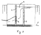
- Figure 1 is a sectional front view along the line A in figure 2; figure 2 is a top view and figure 3 is a cross sectional side view along the line B in figure 1 of a weir according to the invention.
- a second, at least substantially water tight water retaining body 3 can be located, such that between both water retaining bodies a buffer reservoir 4 is formed.
- a buffer reservoir 4 is formed between both water retaining bodies 3.
- the buffer reservoir 4 is emptied through the turbine untill a level below the upper edge area of the turbine.
- the turbine 2 can e.g. come to a hold.
- the buffer reservoir can be exhausted as far as possible, or if a buffer reservoir is not present, the turbine can remain active untill a water level as low as possible.
- peaks in the water supply can be exhausted by bypassing the turbine without causing an increase of the upstream water level.
- other implements for this are feasible, such as drain valves in the water retaining element.
Landscapes
- Engineering & Computer Science (AREA)
- Chemical & Material Sciences (AREA)
- Combustion & Propulsion (AREA)
- Mechanical Engineering (AREA)
- General Engineering & Computer Science (AREA)
- Hydraulic Turbines (AREA)
- Other Liquid Machine Or Engine Such As Wave Power Use (AREA)
Applications Claiming Priority (2)
| Application Number | Priority Date | Filing Date | Title |
|---|---|---|---|
| NL1007668 | 1997-12-02 | ||
| NL1007668 | 1997-12-02 |
Publications (2)
| Publication Number | Publication Date |
|---|---|
| EP0921308A2 true EP0921308A2 (fr) | 1999-06-09 |
| EP0921308A3 EP0921308A3 (fr) | 2001-04-18 |
Family
ID=19766091
Family Applications (1)
| Application Number | Title | Priority Date | Filing Date |
|---|---|---|---|
| EP98204019A Withdrawn EP0921308A3 (fr) | 1997-12-02 | 1998-12-02 | Turbine hydraulique installée submergée dans un barrage |
Country Status (1)
| Country | Link |
|---|---|
| EP (1) | EP0921308A3 (fr) |
Cited By (2)
| Publication number | Priority date | Publication date | Assignee | Title |
|---|---|---|---|---|
| EP1281862A1 (fr) * | 2001-07-30 | 2003-02-05 | Hans Dr. Grassmann | Turbine au fil de l'eau |
| WO2013123923A1 (fr) * | 2012-02-21 | 2013-08-29 | LORENZ, Hermann Heinz | Centrale électrique |
Family Cites Families (4)
| Publication number | Priority date | Publication date | Assignee | Title |
|---|---|---|---|---|
| FR906688A (fr) * | 1943-01-11 | 1946-01-16 | Groupe de machines composé d'une turbine à courant axial et d'une machine électrique | |
| CH347253A (de) * | 1957-01-19 | 1960-06-30 | Escher Wyss Ag | Rohrturbinen- oder Rohrpumpenanlage |
| DE2557989A1 (de) * | 1975-12-22 | 1977-07-21 | Escher Wyss Gmbh | Anlage mit rohrturbine oder rohrpumpe, deren laufrad feststehende schaufeln aufweist |
| JPS55139979A (en) * | 1979-04-18 | 1980-11-01 | Fuji Electric Co Ltd | Electricity generating plant of cylindrical water wheel |
-
1998
- 1998-12-02 EP EP98204019A patent/EP0921308A3/fr not_active Withdrawn
Non-Patent Citations (1)
| Title |
|---|
| None |
Cited By (2)
| Publication number | Priority date | Publication date | Assignee | Title |
|---|---|---|---|---|
| EP1281862A1 (fr) * | 2001-07-30 | 2003-02-05 | Hans Dr. Grassmann | Turbine au fil de l'eau |
| WO2013123923A1 (fr) * | 2012-02-21 | 2013-08-29 | LORENZ, Hermann Heinz | Centrale électrique |
Also Published As
| Publication number | Publication date |
|---|---|
| EP0921308A3 (fr) | 2001-04-18 |
Similar Documents
| Publication | Publication Date | Title |
|---|---|---|
| US8536723B2 (en) | Integrated hydroelectric power-generating system and energy storage device | |
| US20090175723A1 (en) | Undershot impulse jet driven water turbine having an improved vane configuration and radial gate for optimal hydroelectric power generation and water level control | |
| WO2004107527A2 (fr) | Hydrogénérateur submersible de basse chute à pas dynamique variable | |
| US5905311A (en) | Integrated hydroelectric unit | |
| US7503744B1 (en) | Undershot impulse jet driven waterwheel having an automatically adjustable radial gate for optimal hydroelectric power generation and water level control | |
| EP0921308A2 (fr) | Turbine hydraulique installée submergée dans un barrage | |
| JP4653036B2 (ja) | 水力発電装置 | |
| RU2020260C1 (ru) | Речная береговая гидроэлектростанция | |
| WO2012008938A1 (fr) | Système intégré de génération d'électricité hydroélectrique et dispositif de stockage d'énergie | |
| JP2001172948A (ja) | 揚水発電設備 | |
| JP2017053320A (ja) | 発電装置 | |
| US4358220A (en) | Functionally transformable dam | |
| JP2005048603A (ja) | 水力自家発電装置 | |
| JPS58101269A (ja) | 全没型水流駆動原動力設備 | |
| JP2004068655A (ja) | 定水量開放型水車発電装置 | |
| NL1011283C2 (nl) | Inrichting en werkwijze voor het winnen van energie uit een mediumstroom. | |
| NL1010704C2 (nl) | Inrichting en werkwijze voor het winnen van energie uit een mediumstroom. | |
| Mobley et al. | Surface water pumps to improve dissolved oxygen content of hydropower releases | |
| CN113006012A (zh) | 漂浮式涡轮水力发电小型基站 | |
| RU2804790C1 (ru) | Береговая проточная гидроэлектростанция | |
| KR102581083B1 (ko) | 수중매입형 소수력 발전장치 | |
| RU2213881C2 (ru) | Гидроэнергетическая установка "лена-река" | |
| CN221568691U (zh) | 可水平或竖直安装的水轮、平轴式水轮机及垂直式水轮机 | |
| JP3892079B2 (ja) | バルブ型水車発電機 | |
| US11131288B2 (en) | Horizontal axis pi-pitch water turbine with reduced drag |
Legal Events
| Date | Code | Title | Description |
|---|---|---|---|
| PUAI | Public reference made under article 153(3) epc to a published international application that has entered the european phase |
Free format text: ORIGINAL CODE: 0009012 |
|
| AK | Designated contracting states |
Kind code of ref document: A2 Designated state(s): AT BE CH CY DE DK ES FI FR GB GR IE IT LI LU MC NL PT SE |
|
| AX | Request for extension of the european patent |
Free format text: AL;LT;LV;MK;RO;SI |
|
| RAP1 | Party data changed (applicant data changed or rights of an application transferred) |
Owner name: HYDRORING B.V. |
|
| PUAL | Search report despatched |
Free format text: ORIGINAL CODE: 0009013 |
|
| AK | Designated contracting states |
Kind code of ref document: A3 Designated state(s): AT BE CH CY DE DK ES FI FR GB GR IE IT LI LU MC NL PT SE |
|
| AX | Request for extension of the european patent |
Free format text: AL;LT;LV;MK;RO;SI |
|
| AKX | Designation fees paid | ||
| REG | Reference to a national code |
Ref country code: DE Ref legal event code: 8566 |
|
| STAA | Information on the status of an ep patent application or granted ep patent |
Free format text: STATUS: THE APPLICATION IS DEEMED TO BE WITHDRAWN |
|
| 18D | Application deemed to be withdrawn |
Effective date: 20011019 |