EP0921328A2 - Douille avec une collerette médiane, son utilisation et son procédé de fabrication - Google Patents
Douille avec une collerette médiane, son utilisation et son procédé de fabrication Download PDFInfo
- Publication number
- EP0921328A2 EP0921328A2 EP98121685A EP98121685A EP0921328A2 EP 0921328 A2 EP0921328 A2 EP 0921328A2 EP 98121685 A EP98121685 A EP 98121685A EP 98121685 A EP98121685 A EP 98121685A EP 0921328 A2 EP0921328 A2 EP 0921328A2
- Authority
- EP
- European Patent Office
- Prior art keywords
- bearing bush
- collar
- support body
- socket
- bearing
- Prior art date
- Legal status (The legal status is an assumption and is not a legal conclusion. Google has not performed a legal analysis and makes no representation as to the accuracy of the status listed.)
- Granted
Links
- 238000004519 manufacturing process Methods 0.000 title claims abstract description 15
- 238000000034 method Methods 0.000 title description 5
- 239000011324 bead Substances 0.000 claims abstract description 14
- 239000000463 material Substances 0.000 claims abstract description 14
- 239000012791 sliding layer Substances 0.000 claims abstract description 13
- 239000010410 layer Substances 0.000 claims abstract description 5
- 238000006073 displacement reaction Methods 0.000 claims abstract description 3
- 239000013013 elastic material Substances 0.000 claims description 4
- 238000009434 installation Methods 0.000 description 4
- 230000006835 compression Effects 0.000 description 3
- 238000007906 compression Methods 0.000 description 3
- BASFCYQUMIYNBI-UHFFFAOYSA-N platinum Chemical compound [Pt] BASFCYQUMIYNBI-UHFFFAOYSA-N 0.000 description 3
- 230000004323 axial length Effects 0.000 description 2
- 238000000576 coating method Methods 0.000 description 2
- 239000004744 fabric Substances 0.000 description 2
- 101100390736 Danio rerio fign gene Proteins 0.000 description 1
- 101100390738 Mus musculus Fign gene Proteins 0.000 description 1
- 229910000831 Steel Inorganic materials 0.000 description 1
- 230000000712 assembly Effects 0.000 description 1
- 238000000429 assembly Methods 0.000 description 1
- 239000011248 coating agent Substances 0.000 description 1
- 230000008878 coupling Effects 0.000 description 1
- 238000010168 coupling process Methods 0.000 description 1
- 238000005859 coupling reaction Methods 0.000 description 1
- 230000003247 decreasing effect Effects 0.000 description 1
- 238000003780 insertion Methods 0.000 description 1
- 230000037431 insertion Effects 0.000 description 1
- 230000003993 interaction Effects 0.000 description 1
- 239000000314 lubricant Substances 0.000 description 1
- 239000002184 metal Substances 0.000 description 1
- 239000010959 steel Substances 0.000 description 1
Images



Classifications
-
- F—MECHANICAL ENGINEERING; LIGHTING; HEATING; WEAPONS; BLASTING
- F16—ENGINEERING ELEMENTS AND UNITS; GENERAL MEASURES FOR PRODUCING AND MAINTAINING EFFECTIVE FUNCTIONING OF MACHINES OR INSTALLATIONS; THERMAL INSULATION IN GENERAL
- F16C—SHAFTS; FLEXIBLE SHAFTS; ELEMENTS OR CRANKSHAFT MECHANISMS; ROTARY BODIES OTHER THAN GEARING ELEMENTS; BEARINGS
- F16C35/00—Rigid support of bearing units; Housings, e.g. caps, covers
- F16C35/02—Rigid support of bearing units; Housings, e.g. caps, covers in the case of sliding-contact bearings
-
- F—MECHANICAL ENGINEERING; LIGHTING; HEATING; WEAPONS; BLASTING
- F16—ENGINEERING ELEMENTS AND UNITS; GENERAL MEASURES FOR PRODUCING AND MAINTAINING EFFECTIVE FUNCTIONING OF MACHINES OR INSTALLATIONS; THERMAL INSULATION IN GENERAL
- F16C—SHAFTS; FLEXIBLE SHAFTS; ELEMENTS OR CRANKSHAFT MECHANISMS; ROTARY BODIES OTHER THAN GEARING ELEMENTS; BEARINGS
- F16C11/00—Pivots; Pivotal connections
- F16C11/04—Pivotal connections
-
- F—MECHANICAL ENGINEERING; LIGHTING; HEATING; WEAPONS; BLASTING
- F16—ENGINEERING ELEMENTS AND UNITS; GENERAL MEASURES FOR PRODUCING AND MAINTAINING EFFECTIVE FUNCTIONING OF MACHINES OR INSTALLATIONS; THERMAL INSULATION IN GENERAL
- F16C—SHAFTS; FLEXIBLE SHAFTS; ELEMENTS OR CRANKSHAFT MECHANISMS; ROTARY BODIES OTHER THAN GEARING ELEMENTS; BEARINGS
- F16C33/00—Parts of bearings; Special methods for making bearings or parts thereof
- F16C33/02—Parts of sliding-contact bearings
- F16C33/04—Brasses; Bushes; Linings
-
- Y—GENERAL TAGGING OF NEW TECHNOLOGICAL DEVELOPMENTS; GENERAL TAGGING OF CROSS-SECTIONAL TECHNOLOGIES SPANNING OVER SEVERAL SECTIONS OF THE IPC; TECHNICAL SUBJECTS COVERED BY FORMER USPC CROSS-REFERENCE ART COLLECTIONS [XRACs] AND DIGESTS
- Y10—TECHNICAL SUBJECTS COVERED BY FORMER USPC
- Y10T—TECHNICAL SUBJECTS COVERED BY FORMER US CLASSIFICATION
- Y10T29/00—Metal working
- Y10T29/49—Method of mechanical manufacture
- Y10T29/49636—Process for making bearing or component thereof
- Y10T29/49643—Rotary bearing
- Y10T29/49647—Plain bearing
- Y10T29/49668—Sleeve or bushing making
- Y10T29/49671—Strip or blank material shaping
- Y10T29/49673—Die-press shaping
- Y10T29/49675—Die-press shaping having inner lining layer
Definitions
- the invention relates to a bearing bush with a support body on it Inner surface has at least one layer, in particular a sliding layer as well as their use and the manufacturing process.
- Bearing bushes are used in many different ways, e.g. in door hinges, as Roller bearings, pedal bearings in flexible joints, etc.
- the sockets Depending on the application and installation position, the sockets have one or two bundles (end bundles) on one or both ends of the socket.
- the Bushings are installed with oversize, which ensures an immovable fit of the Jack is guaranteed. But this only works if the socket is in a correspondingly massive component is pressed.
- a pedal slide bearing in which the bushing, in a pipe is stored, follow the tilting movements of the pipe to a limited extent can.
- the socket points outwards pointing bead that can move in a recess that in an annular component surrounding the bush is provided.
- the Bush is made of steel and has no sliding coatings.
- the bead is open on the inside and has radial slots distributed over the circumference, whereby the stability of the bead is significantly weakened, so that a such a socket for a rigid installation with lateral loads is not is suitable because over time the socket loosens and the original one Installation position leaves.
- US 1,793,874 describes a bearing that has a curved bushing in which is inserted a sliding fabric.
- the socket is from a support or Retaining ring surrounded by one or two bead-shaped on the outside Deformations for fixing in a housing. Between the socket and the holder is also a sliding fabric, so that the socket is movably mounted in the holder. This storage is due to the The number of components is complex and expensive and it also requires one correspondingly large space requirements.
- the object of the invention is therefore a bearing bush that without additional components can be installed and ensures a tight fit, especially in Interaction with elastic components. It is also the job of Invention, a corresponding manufacturing process for such bushings to provide.
- a bulge becomes under a closed bulge or covenant understood or bundle, in which the inner surfaces lie against each other.
- This is the waistband is not only space-saving, but also more stable than beads Gap (so-called open beads).
- the outer surfaces of the collar are preferably parallel to the longitudinal axis of the Bearing bush aligned. This has the advantage that the federal government on the surface Component is present in which the bearing bush is installed. It becomes one improved fastening achieved.
- the radial extension r of the bead is preferably greater than the axial one Extension a.
- One or more central bundles allow a defined installation position without Additional components. For example, a component whose material thickness is less than the axial length of the bush between two central bundles to be ordered.
- one can also be used asymmetrical fastening of the component can be realized.
- Can too several components can be connected to a socket if the socket is a Corresponding number of bundles, this can be middle and / or final bundles be.
- Such bushings can be used as an insert for a roll of elastic Material, especially rubber can be used.
- a pedal bearing according to the invention is characterized in that the hub and bushes in one piece in the form of a bush are formed with two central bundles. Between the two funds is the pedal lever arranged or fastened.
- the advantage of this pedal mounting is that instead of the usual three components - a hub and two Collar bushings - only one component, namely the bushing according to the invention with two Mittelbunden is required, which reduces the manufacturing and assembly costs can be.
- a bearing bush with at least one central collar and with at least one End collar can be used as a bearing for a flexible joint, especially for a Steering column can be used.
- the manufacturing process is based on a conventional process manufactured bearing bush from, but which has the special feature that the Support body in at least one annular from the socket ends spaced area exposed on its inner surface. In this exposed Area is created in the actual manufacturing process of the waistband.
- This prefabricated bearing bush is usually only processed by the processor provided with the central bundle (s) and depending on the application connected with other components.
- the prefabricated bearing bush is therefore Subject matter of claim 2.
- This prefabricated bearing bush can already be used with one or two Endbands.
- the manufacturing process is characterized in that such prefabricated bearing bush is used, the support body in at least an area spaced from the socket ends on its inner surface it is exposed that an inner mandrel is inserted into this bearing bush, that this Bearing bush on its outer surface leaving at least one gap free, which is opposite the exposed area is held and that the Bearing bush in the axial direction with material displacement into the gap Training a federal government is upset.
- the socket 2 has a support body 3 which has a sliding layer 4 on its inner surface having.
- a sliding layer 4 on its inner surface having.
- the two inner surfaces 33 of the federal government 6, which by the Sliding layer material are formed, are immediately without space on each other.
- the two outer surfaces 31 and 32 of the federal government 6 are vertical aligned with the longitudinal axis 30 of the bearing bush 2.
- the radial extension r is greater than the axial extension a.
- This socket 2 is provided for the storage of a rubber roller 10 has a receptacle 11 and a central recess 12.
- the socket 2 is, as shown in Fig. 2, pressed into the rubber roller 10 (arrow F) until the central collar 6 snaps into the recess 12.
- the location of the Bushing 2 is defined by the recess 12 and the central collar 6, the collar 6 also fixes the position of the socket at the same time. A twisting or slipping out of the bearing bush during operation as an impeller or The like cannot occur.
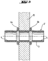
- FIG. 3 is a further embodiment of a bearing bush 2 ' shown, which also has a support body 3 on the inner surface carries a sliding layer 4.
- This socket 2 ' has two central collars 6a and 6b, between which a plate, for example a pedal lever 13, is arranged.
- a plate for example a pedal lever 13
- a flexible joint 14 which has a universal joint holder 16, a steering column part 17 and between these two components an elastic Disc 15 includes.
- Components 16 and 17 are connected via a pin 18 connected to each other, which is in a bearing bush 2 ''.
- the elastic Washer 15 deforms under load, so that the pin 18 is both a can perform axial movement as well as a rotary movement. This is it necessary that the bolt in the 2 '' bushing spans much of its length to be led.
- the component 17 has a relatively low material thickness has, it is necessary that the socket 2 'clearly compared to the component 17 projects. In the prior art, this would be additional components required, then plugged into the corresponding sockets with end collars should be.
- Bearing bushing 2 '' In the embodiment shown here is only one Bearing bushing 2 '' required, which has a central collar 6 and an end collar 7 having. The distance between the end collar 7 and the central collar 6 is on the Adjusted material thickness of the steering column part 17. This is a asymmetrical fastening.
- 5a shows the top view of a circuit board 8 which is used for Production of a bearing bush with two central collars is provided. Accordingly, the board has exposed areas 5a and 5b in which the coating for the sliding layer 4 has been removed. There is also Possibility to close the board 8 only in the corresponding areas coat so that areas 5a and 5b are exposed.
- Fig. 5b is a section through the board 8 along the line V-V shown so that the exposed areas 5a and 5b clearly as grooves are seen.
- a socket made from this board 8 is shown, the Use as a prefabricated socket in the actual manufacturing process finds how he in connection with the fig. 6a and 6b.
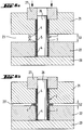
- the tool shown in Fig. 6a has a base plate 20 and two Rings 21 and 22 arranged one above the other. These rings 21, 22 hold the Prefabricated bearing bush 1 on its outer surface, the two rings 21 and 22 are spaced from each other so that between the two Wrestling gap 23 remains.
- the rings have in the area of the gap 23 21, 22 rounded edges 24 and 25.
- the gap 23 is in the area of exposed area 5 is arranged because in this area of Mittelbund should be trained.
- the curves 24 and 25 are required so that the support body material 4th in the area of the bead 6 is not damaged by a sharp edge, what would affect the stability of the bead 6.
- the inner surface of the socket 2 is almost completely in the region of the bead 6 with sliding layer material proven because the entire uncoated support body material for training the bead 6 was used.
Landscapes
- Engineering & Computer Science (AREA)
- General Engineering & Computer Science (AREA)
- Mechanical Engineering (AREA)
- Sliding-Contact Bearings (AREA)
- Support Of The Bearing (AREA)
- Springs (AREA)
Applications Claiming Priority (2)
| Application Number | Priority Date | Filing Date | Title |
|---|---|---|---|
| DE19753111A DE19753111A1 (de) | 1997-11-29 | 1997-11-29 | Lagerbuchse mit Mittelbund sowie deren Verwendung und Herstellungsverfahren |
| DE19753111 | 1997-11-29 |
Publications (3)
| Publication Number | Publication Date |
|---|---|
| EP0921328A2 true EP0921328A2 (fr) | 1999-06-09 |
| EP0921328A3 EP0921328A3 (fr) | 1999-08-11 |
| EP0921328B1 EP0921328B1 (fr) | 2001-10-04 |
Family
ID=7850305
Family Applications (1)
| Application Number | Title | Priority Date | Filing Date |
|---|---|---|---|
| EP98121685A Expired - Lifetime EP0921328B1 (fr) | 1997-11-29 | 1998-11-13 | Douille avec une collerette médiane, son utilisation et son procédé de fabrication |
Country Status (5)
| Country | Link |
|---|---|
| US (2) | US6231239B1 (fr) |
| EP (1) | EP0921328B1 (fr) |
| JP (1) | JPH11230169A (fr) |
| AT (1) | ATE206508T1 (fr) |
| DE (2) | DE19753111A1 (fr) |
Cited By (1)
| Publication number | Priority date | Publication date | Assignee | Title |
|---|---|---|---|---|
| DE10035753A1 (de) * | 2000-07-22 | 2002-03-28 | Zahnradfabrik Friedrichshafen | Zylindrische Lagerbuchse |
Families Citing this family (16)
| Publication number | Priority date | Publication date | Assignee | Title |
|---|---|---|---|---|
| DE19940733A1 (de) * | 1999-08-27 | 2001-03-01 | Schaeffler Waelzlager Ohg | Linearwälzlager mit Flansch |
| US6955237B1 (en) | 2003-06-20 | 2005-10-18 | Polaris Industries Inc. | Snowmobile having an adjustable ski stance |
| DE202005005827U1 (de) * | 2005-04-11 | 2005-06-16 | Igus Gmbh | Gleitlager und Gleitlagersystem |
| DE102006031289A1 (de) * | 2006-05-10 | 2007-11-15 | Heiko Schmidt | Gelenkbuchse |
| US20110262065A1 (en) * | 2010-04-26 | 2011-10-27 | Babu Dharani U | Bearing Assembly With T-Shaped Bearing Member |
| DE102011000526A1 (de) * | 2011-02-04 | 2012-08-23 | Koki Technik Transmission Systems Gmbh | Gleitlagerbuchse |
| CN203005509U (zh) * | 2011-09-26 | 2013-06-19 | 爱信精机株式会社 | 车辆的转向装置 |
| WO2013064655A1 (fr) * | 2011-11-02 | 2013-05-10 | Mauser-Werke Oberndorf Maschinenbau Gmbh | Procédé et dispositif d'introduction d'une douille de palier |
| ES2948109T3 (es) * | 2015-06-30 | 2023-08-31 | Saint Gobain Performance Plastics Corp | Cojinete plano |
| WO2017216064A1 (fr) * | 2016-06-16 | 2017-12-21 | Saint-Gobain Performance Plastics Pampus Gmbh | Ensemble à palier lisse |
| PL3494316T3 (pl) | 2016-08-02 | 2022-09-19 | Saint-Gobain Performance Plastics Corporation | Łożysko |
| US10684638B2 (en) * | 2018-01-23 | 2020-06-16 | Electrolux Home Products, Inc. | Appliance knob stabilization device and related method |
| WO2021113599A1 (fr) * | 2019-12-06 | 2021-06-10 | Saint-Gobain Performance Plastics Corporation | Palier à bride, assemblage, et procédé de fabrication et d'utilisation de celui-ci |
| CN111922637B (zh) * | 2020-07-21 | 2022-04-08 | 浙江长盛滑动轴承股份有限公司 | 一种保证轴套同轴度的制造工艺 |
| JP2024520214A (ja) | 2021-07-02 | 2024-05-22 | サン-ゴバン パフォーマンス プラスチックス パンプス ゲゼルシャフト ミット ベシュレンクテル ハフツング | フランジ付き軸受、アセンブリ、並びにその製造方法及び使用方法 |
| KR20240124302A (ko) | 2021-12-21 | 2024-08-16 | 생-고뱅 퍼포먼스 플라스틱스 코포레이션 | 리브를 갖는 전기 전도성 베어링, 및 이를 제조 및 사용하는 방법 |
Family Cites Families (17)
| Publication number | Priority date | Publication date | Assignee | Title |
|---|---|---|---|---|
| DE195349C (fr) | ||||
| US1793874A (en) * | 1928-04-19 | 1931-02-24 | O & S Bearing Co | Self-aligning self-lubricating bearing and method of forming the same |
| US1892175A (en) * | 1929-06-10 | 1932-12-27 | Cleveland Graphite Bronze Co | Method of making bearing sleeves |
| US1821122A (en) * | 1929-07-17 | 1931-09-01 | Hydraulic Pressed Bearing Comp | Bearing sleeve and method of making same |
| DE841087C (de) * | 1940-04-07 | 1952-06-13 | Focke Wulf Flugzeugbau G M B H | Elastisch nachgiebiges Pendelgleitlager |
| US2738570A (en) * | 1950-09-11 | 1956-03-20 | Heim Company | Method of mounting a bearing to compensate for misalignment and prevent splitting of outer member |
| US2804679A (en) * | 1954-08-23 | 1957-09-03 | Southwest Products Co | Method of making bearings and rod end bearings |
| US2904874A (en) * | 1956-11-20 | 1959-09-22 | Thompson Ramo Wooldridge Inc | Method of manufacturing connecting rod bearings |
| DE1854990U (de) * | 1962-03-21 | 1962-07-12 | Sahlin Continental Engineering | Gleitlager aus kunststoff. |
| US3199173A (en) * | 1962-10-29 | 1965-08-10 | Universal American Corp | Method of making a flanged bearing |
| US3351999A (en) * | 1965-11-04 | 1967-11-14 | Heim Universal Corp | Manufacture of self-aligned bearings |
| GB1458047A (en) * | 1973-11-20 | 1976-12-08 | Atomic Energy Authority Uk | Bearings and journal assemblies process for preparing aryl-substituted pyridones |
| DE2406460A1 (de) * | 1974-02-11 | 1975-08-14 | Glyco Metall Werke | Buchse, insbesondere gleitlager oder gehaeusebuchse mit angeformtem, schmalem bund mit beliebigen bunddicken, sowie verfahren und vorrichtung zu ihrer herstellung |
| US4048703A (en) * | 1975-02-14 | 1977-09-20 | Glyco-Metall-Werke Daelen & Loos Gmbh | Collar sleeves and process and tool for the manufacture thereof |
| US4231623A (en) * | 1978-10-02 | 1980-11-04 | Tecumseh Products Company | Steel connecting rod bearing liner for internal combustion engines |
| JPS6133719A (ja) * | 1984-07-26 | 1986-02-17 | Daido Metal Kogyo Kk | つば付ブシユの製造方法およびその装置 |
| JPH0785821B2 (ja) * | 1992-01-31 | 1995-09-20 | 大同メタル工業株式会社 | ブッシュの成形方法 |
-
1997
- 1997-11-29 DE DE19753111A patent/DE19753111A1/de not_active Ceased
-
1998
- 1998-11-13 EP EP98121685A patent/EP0921328B1/fr not_active Expired - Lifetime
- 1998-11-13 AT AT98121685T patent/ATE206508T1/de not_active IP Right Cessation
- 1998-11-13 DE DE59801626T patent/DE59801626D1/de not_active Expired - Fee Related
- 1998-11-27 JP JP10337985A patent/JPH11230169A/ja not_active Withdrawn
- 1998-11-27 US US09/200,690 patent/US6231239B1/en not_active Expired - Fee Related
-
2000
- 2000-04-18 US US09/552,446 patent/US6282792B1/en not_active Expired - Fee Related
Cited By (2)
| Publication number | Priority date | Publication date | Assignee | Title |
|---|---|---|---|---|
| DE10035753A1 (de) * | 2000-07-22 | 2002-03-28 | Zahnradfabrik Friedrichshafen | Zylindrische Lagerbuchse |
| DE10035753B4 (de) * | 2000-07-22 | 2011-06-16 | Zf Friedrichshafen Ag | Zylindrische Lagerbuchse |
Also Published As
| Publication number | Publication date |
|---|---|
| EP0921328B1 (fr) | 2001-10-04 |
| DE59801626D1 (de) | 2001-11-08 |
| DE19753111A1 (de) | 1999-06-10 |
| ATE206508T1 (de) | 2001-10-15 |
| JPH11230169A (ja) | 1999-08-27 |
| US6231239B1 (en) | 2001-05-15 |
| EP0921328A3 (fr) | 1999-08-11 |
| US6282792B1 (en) | 2001-09-04 |
Similar Documents
| Publication | Publication Date | Title |
|---|---|---|
| EP0921328B1 (fr) | Douille avec une collerette médiane, son utilisation et son procédé de fabrication | |
| DE10131075B4 (de) | Aggregatelager in Buchsenform | |
| DE10023602C2 (de) | Kugelhülsengelenk | |
| EP0686748B1 (fr) | Charnière en tÔle sans fiche et sans entretien pour véhicules | |
| DE10107109C2 (de) | Bundbuchse, Verfahren zu ihrer Herstellung und Biegewerkzeug zur Herstellung von Bunden an einer Buchse | |
| DE102005043234B4 (de) | Verfahren zur Herstellung eines elastomeren Buchsenlagers | |
| DE3826987A1 (de) | Verfahren zur herstellung eines kugelgelenkes | |
| EP3157769B1 (fr) | Procédé servant à fabriquer un composant de châssis | |
| EP1456544B1 (fr) | Articulation spherique | |
| DE2050893A1 (de) | Selbstzentnerende sphärische Lagereinrichtung und Verfahren zur Her stellung derselben | |
| DE102007037704A1 (de) | Lageranordnung mit einer Lagerbuchse und Verfahren zur Herstellung einer Lagerbuchse einer Lageranordnung | |
| AT14987U1 (de) | Verfahren zum Verbinden von Möbelbeschlagsteilen und Möbelbeschlag | |
| EP0924442B1 (fr) | Coussinet et procédé de sa fabrication | |
| DE69700991T2 (de) | Federringe | |
| DE102020102971B4 (de) | Gelenkteil mit einem Lagerelement | |
| DE10234305A1 (de) | Dichtring zur Abdichtung eines Längenausgleichs einer Gelenkwelle | |
| DE60218395T2 (de) | Paddelträger | |
| EP1391619B1 (fr) | Joint à rotule | |
| DE19735753A1 (de) | Drehstabanordnung | |
| DE60121338T2 (de) | Verfahren und vorrichtung zum befestigen eines kolbens oder einer kolbenstangeverbindung an einer kolbenstange | |
| EP0672463A1 (fr) | Rouleau à peindre | |
| EP1964694B1 (fr) | Système d'articulation et/ou de palier, en particulier articulation à douille destinée à relier des éléments de guidage de roue d'un véhicule, ainsi que procédé de fabrication d'un système d'articulation et/ou de palier | |
| DE102006031289A1 (de) | Gelenkbuchse | |
| DE202010005349U1 (de) | Doppelstanzbuchse sowie System aus einem Rohr und einer Doppelstanzbuchse | |
| WO2001023771A1 (fr) | Dispositif de guidage d'axe pour frein a disque a etrier flottant |
Legal Events
| Date | Code | Title | Description |
|---|---|---|---|
| PUAI | Public reference made under article 153(3) epc to a published international application that has entered the european phase |
Free format text: ORIGINAL CODE: 0009012 |
|
| AK | Designated contracting states |
Kind code of ref document: A2 Designated state(s): AT DE FR GB IT |
|
| AX | Request for extension of the european patent |
Free format text: AL;LT;LV;MK;RO;SI |
|
| PUAL | Search report despatched |
Free format text: ORIGINAL CODE: 0009013 |
|
| AK | Designated contracting states |
Kind code of ref document: A3 Designated state(s): AT BE CH CY DE DK ES FI FR GB GR IE IT LI LU MC NL PT SE |
|
| AX | Request for extension of the european patent |
Free format text: AL;LT;LV;MK;RO;SI |
|
| RIC1 | Information provided on ipc code assigned before grant |
Free format text: 6F 16C 11/00 A, 6F 16C 33/08 B |
|
| 17P | Request for examination filed |
Effective date: 19990714 |
|
| 17Q | First examination report despatched |
Effective date: 19991228 |
|
| AKX | Designation fees paid |
Free format text: AT DE FR GB IT |
|
| GRAG | Despatch of communication of intention to grant |
Free format text: ORIGINAL CODE: EPIDOS AGRA |
|
| GRAG | Despatch of communication of intention to grant |
Free format text: ORIGINAL CODE: EPIDOS AGRA |
|
| GRAH | Despatch of communication of intention to grant a patent |
Free format text: ORIGINAL CODE: EPIDOS IGRA |
|
| RAP1 | Party data changed (applicant data changed or rights of an application transferred) |
Owner name: FEDERAL-MOGUL WIESBADEN GMBH & CO.KG |
|
| GRAH | Despatch of communication of intention to grant a patent |
Free format text: ORIGINAL CODE: EPIDOS IGRA |
|
| GRAA | (expected) grant |
Free format text: ORIGINAL CODE: 0009210 |
|
| AK | Designated contracting states |
Kind code of ref document: B1 Designated state(s): AT DE FR GB IT |
|
| REF | Corresponds to: |
Ref document number: 206508 Country of ref document: AT Date of ref document: 20011015 Kind code of ref document: T |
|
| REF | Corresponds to: |
Ref document number: 59801626 Country of ref document: DE Date of ref document: 20011108 |
|
| PG25 | Lapsed in a contracting state [announced via postgrant information from national office to epo] |
Ref country code: AT Free format text: LAPSE BECAUSE OF NON-PAYMENT OF DUE FEES Effective date: 20011113 |
|
| REG | Reference to a national code |
Ref country code: GB Ref legal event code: IF02 |
|
| GBT | Gb: translation of ep patent filed (gb section 77(6)(a)/1977) |
Effective date: 20011218 |
|
| ET | Fr: translation filed | ||
| PLBE | No opposition filed within time limit |
Free format text: ORIGINAL CODE: 0009261 |
|
| STAA | Information on the status of an ep patent application or granted ep patent |
Free format text: STATUS: NO OPPOSITION FILED WITHIN TIME LIMIT |
|
| 26N | No opposition filed | ||
| PGFP | Annual fee paid to national office [announced via postgrant information from national office to epo] |
Ref country code: GB Payment date: 20041004 Year of fee payment: 7 |
|
| PGFP | Annual fee paid to national office [announced via postgrant information from national office to epo] |
Ref country code: FR Payment date: 20041105 Year of fee payment: 7 |
|
| PGFP | Annual fee paid to national office [announced via postgrant information from national office to epo] |
Ref country code: DE Payment date: 20041130 Year of fee payment: 7 |
|
| PG25 | Lapsed in a contracting state [announced via postgrant information from national office to epo] |
Ref country code: IT Free format text: LAPSE BECAUSE OF NON-PAYMENT OF DUE FEES;WARNING: LAPSES OF ITALIAN PATENTS WITH EFFECTIVE DATE BEFORE 2007 MAY HAVE OCCURRED AT ANY TIME BEFORE 2007. THE CORRECT EFFECTIVE DATE MAY BE DIFFERENT FROM THE ONE RECORDED. Effective date: 20051113 Ref country code: GB Free format text: LAPSE BECAUSE OF NON-PAYMENT OF DUE FEES Effective date: 20051113 |
|
| PG25 | Lapsed in a contracting state [announced via postgrant information from national office to epo] |
Ref country code: DE Free format text: LAPSE BECAUSE OF NON-PAYMENT OF DUE FEES Effective date: 20060601 |
|
| GBPC | Gb: european patent ceased through non-payment of renewal fee |
Effective date: 20051113 |
|
| PG25 | Lapsed in a contracting state [announced via postgrant information from national office to epo] |
Ref country code: FR Free format text: LAPSE BECAUSE OF NON-PAYMENT OF DUE FEES Effective date: 20060731 |
|
| REG | Reference to a national code |
Ref country code: FR Ref legal event code: ST Effective date: 20060731 |