EP0921367A2 - Herstellung von Stickstoff - Google Patents
Herstellung von Stickstoff Download PDFInfo
- Publication number
- EP0921367A2 EP0921367A2 EP98309443A EP98309443A EP0921367A2 EP 0921367 A2 EP0921367 A2 EP 0921367A2 EP 98309443 A EP98309443 A EP 98309443A EP 98309443 A EP98309443 A EP 98309443A EP 0921367 A2 EP0921367 A2 EP 0921367A2
- Authority
- EP
- European Patent Office
- Prior art keywords
- pressure
- nitrogen
- rectification column
- stream
- separated
- Prior art date
- Legal status (The legal status is an assumption and is not a legal conclusion. Google has not performed a legal analysis and makes no representation as to the accuracy of the status listed.)
- Withdrawn
Links
Images




Classifications
-
- F—MECHANICAL ENGINEERING; LIGHTING; HEATING; WEAPONS; BLASTING
- F25—REFRIGERATION OR COOLING; COMBINED HEATING AND REFRIGERATION SYSTEMS; HEAT PUMP SYSTEMS; MANUFACTURE OR STORAGE OF ICE; LIQUEFACTION SOLIDIFICATION OF GASES
- F25J—LIQUEFACTION, SOLIDIFICATION OR SEPARATION OF GASES OR GASEOUS OR LIQUEFIED GASEOUS MIXTURES BY PRESSURE AND COLD TREATMENT OR BY BRINGING THEM INTO THE SUPERCRITICAL STATE
- F25J3/00—Processes or apparatus for separating the constituents of gaseous or liquefied gaseous mixtures involving the use of liquefaction or solidification
- F25J3/02—Processes or apparatus for separating the constituents of gaseous or liquefied gaseous mixtures involving the use of liquefaction or solidification by rectification, i.e. by continuous interchange of heat and material between a vapour stream and a liquid stream
- F25J3/04—Processes or apparatus for separating the constituents of gaseous or liquefied gaseous mixtures involving the use of liquefaction or solidification by rectification, i.e. by continuous interchange of heat and material between a vapour stream and a liquid stream for air
- F25J3/04151—Purification and (pre-)cooling of the feed air; recuperative heat-exchange with product streams
- F25J3/04187—Cooling of the purified feed air by recuperative heat-exchange; Heat-exchange with product streams
- F25J3/04193—Division of the main heat exchange line in consecutive sections having different functions
- F25J3/04206—Division of the main heat exchange line in consecutive sections having different functions including a so-called "auxiliary vaporiser" for vaporising and producing a gaseous product
- F25J3/04212—Division of the main heat exchange line in consecutive sections having different functions including a so-called "auxiliary vaporiser" for vaporising and producing a gaseous product and simultaneously condensing vapor from a column serving as reflux within the or another column
-
- F—MECHANICAL ENGINEERING; LIGHTING; HEATING; WEAPONS; BLASTING
- F25—REFRIGERATION OR COOLING; COMBINED HEATING AND REFRIGERATION SYSTEMS; HEAT PUMP SYSTEMS; MANUFACTURE OR STORAGE OF ICE; LIQUEFACTION SOLIDIFICATION OF GASES
- F25J—LIQUEFACTION, SOLIDIFICATION OR SEPARATION OF GASES OR GASEOUS OR LIQUEFIED GASEOUS MIXTURES BY PRESSURE AND COLD TREATMENT OR BY BRINGING THEM INTO THE SUPERCRITICAL STATE
- F25J3/00—Processes or apparatus for separating the constituents of gaseous or liquefied gaseous mixtures involving the use of liquefaction or solidification
- F25J3/02—Processes or apparatus for separating the constituents of gaseous or liquefied gaseous mixtures involving the use of liquefaction or solidification by rectification, i.e. by continuous interchange of heat and material between a vapour stream and a liquid stream
- F25J3/04—Processes or apparatus for separating the constituents of gaseous or liquefied gaseous mixtures involving the use of liquefaction or solidification by rectification, i.e. by continuous interchange of heat and material between a vapour stream and a liquid stream for air
- F25J3/04006—Providing pressurised feed air or process streams within or from the air fractionation unit
- F25J3/04078—Providing pressurised feed air or process streams within or from the air fractionation unit providing pressurized products by liquid compression and vaporisation with cold recovery, i.e. so-called internal compression
- F25J3/04084—Providing pressurised feed air or process streams within or from the air fractionation unit providing pressurized products by liquid compression and vaporisation with cold recovery, i.e. so-called internal compression of nitrogen
-
- F—MECHANICAL ENGINEERING; LIGHTING; HEATING; WEAPONS; BLASTING
- F25—REFRIGERATION OR COOLING; COMBINED HEATING AND REFRIGERATION SYSTEMS; HEAT PUMP SYSTEMS; MANUFACTURE OR STORAGE OF ICE; LIQUEFACTION SOLIDIFICATION OF GASES
- F25J—LIQUEFACTION, SOLIDIFICATION OR SEPARATION OF GASES OR GASEOUS OR LIQUEFIED GASEOUS MIXTURES BY PRESSURE AND COLD TREATMENT OR BY BRINGING THEM INTO THE SUPERCRITICAL STATE
- F25J3/00—Processes or apparatus for separating the constituents of gaseous or liquefied gaseous mixtures involving the use of liquefaction or solidification
- F25J3/02—Processes or apparatus for separating the constituents of gaseous or liquefied gaseous mixtures involving the use of liquefaction or solidification by rectification, i.e. by continuous interchange of heat and material between a vapour stream and a liquid stream
- F25J3/04—Processes or apparatus for separating the constituents of gaseous or liquefied gaseous mixtures involving the use of liquefaction or solidification by rectification, i.e. by continuous interchange of heat and material between a vapour stream and a liquid stream for air
- F25J3/04151—Purification and (pre-)cooling of the feed air; recuperative heat-exchange with product streams
- F25J3/04187—Cooling of the purified feed air by recuperative heat-exchange; Heat-exchange with product streams
- F25J3/04193—Division of the main heat exchange line in consecutive sections having different functions
- F25J3/04206—Division of the main heat exchange line in consecutive sections having different functions including a so-called "auxiliary vaporiser" for vaporising and producing a gaseous product
-
- F—MECHANICAL ENGINEERING; LIGHTING; HEATING; WEAPONS; BLASTING
- F25—REFRIGERATION OR COOLING; COMBINED HEATING AND REFRIGERATION SYSTEMS; HEAT PUMP SYSTEMS; MANUFACTURE OR STORAGE OF ICE; LIQUEFACTION SOLIDIFICATION OF GASES
- F25J—LIQUEFACTION, SOLIDIFICATION OR SEPARATION OF GASES OR GASEOUS OR LIQUEFIED GASEOUS MIXTURES BY PRESSURE AND COLD TREATMENT OR BY BRINGING THEM INTO THE SUPERCRITICAL STATE
- F25J3/00—Processes or apparatus for separating the constituents of gaseous or liquefied gaseous mixtures involving the use of liquefaction or solidification
- F25J3/02—Processes or apparatus for separating the constituents of gaseous or liquefied gaseous mixtures involving the use of liquefaction or solidification by rectification, i.e. by continuous interchange of heat and material between a vapour stream and a liquid stream
- F25J3/04—Processes or apparatus for separating the constituents of gaseous or liquefied gaseous mixtures involving the use of liquefaction or solidification by rectification, i.e. by continuous interchange of heat and material between a vapour stream and a liquid stream for air
- F25J3/04151—Purification and (pre-)cooling of the feed air; recuperative heat-exchange with product streams
- F25J3/04187—Cooling of the purified feed air by recuperative heat-exchange; Heat-exchange with product streams
- F25J3/0423—Subcooling of liquid process streams
-
- F—MECHANICAL ENGINEERING; LIGHTING; HEATING; WEAPONS; BLASTING
- F25—REFRIGERATION OR COOLING; COMBINED HEATING AND REFRIGERATION SYSTEMS; HEAT PUMP SYSTEMS; MANUFACTURE OR STORAGE OF ICE; LIQUEFACTION SOLIDIFICATION OF GASES
- F25J—LIQUEFACTION, SOLIDIFICATION OR SEPARATION OF GASES OR GASEOUS OR LIQUEFIED GASEOUS MIXTURES BY PRESSURE AND COLD TREATMENT OR BY BRINGING THEM INTO THE SUPERCRITICAL STATE
- F25J3/00—Processes or apparatus for separating the constituents of gaseous or liquefied gaseous mixtures involving the use of liquefaction or solidification
- F25J3/02—Processes or apparatus for separating the constituents of gaseous or liquefied gaseous mixtures involving the use of liquefaction or solidification by rectification, i.e. by continuous interchange of heat and material between a vapour stream and a liquid stream
- F25J3/04—Processes or apparatus for separating the constituents of gaseous or liquefied gaseous mixtures involving the use of liquefaction or solidification by rectification, i.e. by continuous interchange of heat and material between a vapour stream and a liquid stream for air
- F25J3/04248—Generation of cold for compensating heat leaks or liquid production, e.g. by Joule-Thompson expansion
- F25J3/04284—Generation of cold for compensating heat leaks or liquid production, e.g. by Joule-Thompson expansion using internal refrigeration by open-loop gas work expansion, e.g. of intermediate or oxygen enriched (waste-)streams
- F25J3/0429—Generation of cold for compensating heat leaks or liquid production, e.g. by Joule-Thompson expansion using internal refrigeration by open-loop gas work expansion, e.g. of intermediate or oxygen enriched (waste-)streams of feed air, e.g. used as waste or product air or expanded into an auxiliary column
-
- F—MECHANICAL ENGINEERING; LIGHTING; HEATING; WEAPONS; BLASTING
- F25—REFRIGERATION OR COOLING; COMBINED HEATING AND REFRIGERATION SYSTEMS; HEAT PUMP SYSTEMS; MANUFACTURE OR STORAGE OF ICE; LIQUEFACTION SOLIDIFICATION OF GASES
- F25J—LIQUEFACTION, SOLIDIFICATION OR SEPARATION OF GASES OR GASEOUS OR LIQUEFIED GASEOUS MIXTURES BY PRESSURE AND COLD TREATMENT OR BY BRINGING THEM INTO THE SUPERCRITICAL STATE
- F25J3/00—Processes or apparatus for separating the constituents of gaseous or liquefied gaseous mixtures involving the use of liquefaction or solidification
- F25J3/02—Processes or apparatus for separating the constituents of gaseous or liquefied gaseous mixtures involving the use of liquefaction or solidification by rectification, i.e. by continuous interchange of heat and material between a vapour stream and a liquid stream
- F25J3/04—Processes or apparatus for separating the constituents of gaseous or liquefied gaseous mixtures involving the use of liquefaction or solidification by rectification, i.e. by continuous interchange of heat and material between a vapour stream and a liquid stream for air
- F25J3/04248—Generation of cold for compensating heat leaks or liquid production, e.g. by Joule-Thompson expansion
- F25J3/04284—Generation of cold for compensating heat leaks or liquid production, e.g. by Joule-Thompson expansion using internal refrigeration by open-loop gas work expansion, e.g. of intermediate or oxygen enriched (waste-)streams
- F25J3/0429—Generation of cold for compensating heat leaks or liquid production, e.g. by Joule-Thompson expansion using internal refrigeration by open-loop gas work expansion, e.g. of intermediate or oxygen enriched (waste-)streams of feed air, e.g. used as waste or product air or expanded into an auxiliary column
- F25J3/04303—Lachmann expansion, i.e. expanded into oxygen producing or low pressure column
-
- F—MECHANICAL ENGINEERING; LIGHTING; HEATING; WEAPONS; BLASTING
- F25—REFRIGERATION OR COOLING; COMBINED HEATING AND REFRIGERATION SYSTEMS; HEAT PUMP SYSTEMS; MANUFACTURE OR STORAGE OF ICE; LIQUEFACTION SOLIDIFICATION OF GASES
- F25J—LIQUEFACTION, SOLIDIFICATION OR SEPARATION OF GASES OR GASEOUS OR LIQUEFIED GASEOUS MIXTURES BY PRESSURE AND COLD TREATMENT OR BY BRINGING THEM INTO THE SUPERCRITICAL STATE
- F25J3/00—Processes or apparatus for separating the constituents of gaseous or liquefied gaseous mixtures involving the use of liquefaction or solidification
- F25J3/02—Processes or apparatus for separating the constituents of gaseous or liquefied gaseous mixtures involving the use of liquefaction or solidification by rectification, i.e. by continuous interchange of heat and material between a vapour stream and a liquid stream
- F25J3/04—Processes or apparatus for separating the constituents of gaseous or liquefied gaseous mixtures involving the use of liquefaction or solidification by rectification, i.e. by continuous interchange of heat and material between a vapour stream and a liquid stream for air
- F25J3/04436—Processes or apparatus for separating the constituents of gaseous or liquefied gaseous mixtures involving the use of liquefaction or solidification by rectification, i.e. by continuous interchange of heat and material between a vapour stream and a liquid stream for air using at least a triple pressure main column system
- F25J3/04448—Processes or apparatus for separating the constituents of gaseous or liquefied gaseous mixtures involving the use of liquefaction or solidification by rectification, i.e. by continuous interchange of heat and material between a vapour stream and a liquid stream for air using at least a triple pressure main column system in a double column flowsheet with an intermediate pressure column
-
- F—MECHANICAL ENGINEERING; LIGHTING; HEATING; WEAPONS; BLASTING
- F25—REFRIGERATION OR COOLING; COMBINED HEATING AND REFRIGERATION SYSTEMS; HEAT PUMP SYSTEMS; MANUFACTURE OR STORAGE OF ICE; LIQUEFACTION SOLIDIFICATION OF GASES
- F25J—LIQUEFACTION, SOLIDIFICATION OR SEPARATION OF GASES OR GASEOUS OR LIQUEFIED GASEOUS MIXTURES BY PRESSURE AND COLD TREATMENT OR BY BRINGING THEM INTO THE SUPERCRITICAL STATE
- F25J3/00—Processes or apparatus for separating the constituents of gaseous or liquefied gaseous mixtures involving the use of liquefaction or solidification
- F25J3/02—Processes or apparatus for separating the constituents of gaseous or liquefied gaseous mixtures involving the use of liquefaction or solidification by rectification, i.e. by continuous interchange of heat and material between a vapour stream and a liquid stream
- F25J3/04—Processes or apparatus for separating the constituents of gaseous or liquefied gaseous mixtures involving the use of liquefaction or solidification by rectification, i.e. by continuous interchange of heat and material between a vapour stream and a liquid stream for air
- F25J3/04436—Processes or apparatus for separating the constituents of gaseous or liquefied gaseous mixtures involving the use of liquefaction or solidification by rectification, i.e. by continuous interchange of heat and material between a vapour stream and a liquid stream for air using at least a triple pressure main column system
- F25J3/04454—Processes or apparatus for separating the constituents of gaseous or liquefied gaseous mixtures involving the use of liquefaction or solidification by rectification, i.e. by continuous interchange of heat and material between a vapour stream and a liquid stream for air using at least a triple pressure main column system a main column system not otherwise provided, e.g. serially coupling of columns or more than three pressure levels
-
- F—MECHANICAL ENGINEERING; LIGHTING; HEATING; WEAPONS; BLASTING
- F25—REFRIGERATION OR COOLING; COMBINED HEATING AND REFRIGERATION SYSTEMS; HEAT PUMP SYSTEMS; MANUFACTURE OR STORAGE OF ICE; LIQUEFACTION SOLIDIFICATION OF GASES
- F25J—LIQUEFACTION, SOLIDIFICATION OR SEPARATION OF GASES OR GASEOUS OR LIQUEFIED GASEOUS MIXTURES BY PRESSURE AND COLD TREATMENT OR BY BRINGING THEM INTO THE SUPERCRITICAL STATE
- F25J2200/00—Processes or apparatus using separation by rectification
- F25J2200/10—Processes or apparatus using separation by rectification in a quadruple, or more, column or pressure system
-
- F—MECHANICAL ENGINEERING; LIGHTING; HEATING; WEAPONS; BLASTING
- F25—REFRIGERATION OR COOLING; COMBINED HEATING AND REFRIGERATION SYSTEMS; HEAT PUMP SYSTEMS; MANUFACTURE OR STORAGE OF ICE; LIQUEFACTION SOLIDIFICATION OF GASES
- F25J—LIQUEFACTION, SOLIDIFICATION OR SEPARATION OF GASES OR GASEOUS OR LIQUEFIED GASEOUS MIXTURES BY PRESSURE AND COLD TREATMENT OR BY BRINGING THEM INTO THE SUPERCRITICAL STATE
- F25J2200/00—Processes or apparatus using separation by rectification
- F25J2200/20—Processes or apparatus using separation by rectification in an elevated pressure multiple column system wherein the lowest pressure column is at a pressure well above the minimum pressure needed to overcome pressure drop to reject the products to atmosphere
-
- F—MECHANICAL ENGINEERING; LIGHTING; HEATING; WEAPONS; BLASTING
- F25—REFRIGERATION OR COOLING; COMBINED HEATING AND REFRIGERATION SYSTEMS; HEAT PUMP SYSTEMS; MANUFACTURE OR STORAGE OF ICE; LIQUEFACTION SOLIDIFICATION OF GASES
- F25J—LIQUEFACTION, SOLIDIFICATION OR SEPARATION OF GASES OR GASEOUS OR LIQUEFIED GASEOUS MIXTURES BY PRESSURE AND COLD TREATMENT OR BY BRINGING THEM INTO THE SUPERCRITICAL STATE
- F25J2200/00—Processes or apparatus using separation by rectification
- F25J2200/50—Processes or apparatus using separation by rectification using multiple (re-)boiler-condensers at different heights of the column
-
- F—MECHANICAL ENGINEERING; LIGHTING; HEATING; WEAPONS; BLASTING
- F25—REFRIGERATION OR COOLING; COMBINED HEATING AND REFRIGERATION SYSTEMS; HEAT PUMP SYSTEMS; MANUFACTURE OR STORAGE OF ICE; LIQUEFACTION SOLIDIFICATION OF GASES
- F25J—LIQUEFACTION, SOLIDIFICATION OR SEPARATION OF GASES OR GASEOUS OR LIQUEFIED GASEOUS MIXTURES BY PRESSURE AND COLD TREATMENT OR BY BRINGING THEM INTO THE SUPERCRITICAL STATE
- F25J2200/00—Processes or apparatus using separation by rectification
- F25J2200/50—Processes or apparatus using separation by rectification using multiple (re-)boiler-condensers at different heights of the column
- F25J2200/54—Processes or apparatus using separation by rectification using multiple (re-)boiler-condensers at different heights of the column in the low pressure column of a double pressure main column system
-
- F—MECHANICAL ENGINEERING; LIGHTING; HEATING; WEAPONS; BLASTING
- F25—REFRIGERATION OR COOLING; COMBINED HEATING AND REFRIGERATION SYSTEMS; HEAT PUMP SYSTEMS; MANUFACTURE OR STORAGE OF ICE; LIQUEFACTION SOLIDIFICATION OF GASES
- F25J—LIQUEFACTION, SOLIDIFICATION OR SEPARATION OF GASES OR GASEOUS OR LIQUEFIED GASEOUS MIXTURES BY PRESSURE AND COLD TREATMENT OR BY BRINGING THEM INTO THE SUPERCRITICAL STATE
- F25J2205/00—Processes or apparatus using other separation and/or other processing means
- F25J2205/02—Processes or apparatus using other separation and/or other processing means using simple phase separation in a vessel or drum
-
- F—MECHANICAL ENGINEERING; LIGHTING; HEATING; WEAPONS; BLASTING
- F25—REFRIGERATION OR COOLING; COMBINED HEATING AND REFRIGERATION SYSTEMS; HEAT PUMP SYSTEMS; MANUFACTURE OR STORAGE OF ICE; LIQUEFACTION SOLIDIFICATION OF GASES
- F25J—LIQUEFACTION, SOLIDIFICATION OR SEPARATION OF GASES OR GASEOUS OR LIQUEFIED GASEOUS MIXTURES BY PRESSURE AND COLD TREATMENT OR BY BRINGING THEM INTO THE SUPERCRITICAL STATE
- F25J2235/00—Processes or apparatus involving steps for increasing the pressure or for conveying of liquid process streams
- F25J2235/42—Processes or apparatus involving steps for increasing the pressure or for conveying of liquid process streams the fluid being nitrogen
-
- F—MECHANICAL ENGINEERING; LIGHTING; HEATING; WEAPONS; BLASTING
- F25—REFRIGERATION OR COOLING; COMBINED HEATING AND REFRIGERATION SYSTEMS; HEAT PUMP SYSTEMS; MANUFACTURE OR STORAGE OF ICE; LIQUEFACTION SOLIDIFICATION OF GASES
- F25J—LIQUEFACTION, SOLIDIFICATION OR SEPARATION OF GASES OR GASEOUS OR LIQUEFIED GASEOUS MIXTURES BY PRESSURE AND COLD TREATMENT OR BY BRINGING THEM INTO THE SUPERCRITICAL STATE
- F25J2235/00—Processes or apparatus involving steps for increasing the pressure or for conveying of liquid process streams
- F25J2235/52—Processes or apparatus involving steps for increasing the pressure or for conveying of liquid process streams the fluid being oxygen enriched compared to air ("crude oxygen")
-
- F—MECHANICAL ENGINEERING; LIGHTING; HEATING; WEAPONS; BLASTING
- F25—REFRIGERATION OR COOLING; COMBINED HEATING AND REFRIGERATION SYSTEMS; HEAT PUMP SYSTEMS; MANUFACTURE OR STORAGE OF ICE; LIQUEFACTION SOLIDIFICATION OF GASES
- F25J—LIQUEFACTION, SOLIDIFICATION OR SEPARATION OF GASES OR GASEOUS OR LIQUEFIED GASEOUS MIXTURES BY PRESSURE AND COLD TREATMENT OR BY BRINGING THEM INTO THE SUPERCRITICAL STATE
- F25J2245/00—Processes or apparatus involving steps for recycling of process streams
- F25J2245/42—Processes or apparatus involving steps for recycling of process streams the recycled stream being nitrogen
-
- F—MECHANICAL ENGINEERING; LIGHTING; HEATING; WEAPONS; BLASTING
- F25—REFRIGERATION OR COOLING; COMBINED HEATING AND REFRIGERATION SYSTEMS; HEAT PUMP SYSTEMS; MANUFACTURE OR STORAGE OF ICE; LIQUEFACTION SOLIDIFICATION OF GASES
- F25J—LIQUEFACTION, SOLIDIFICATION OR SEPARATION OF GASES OR GASEOUS OR LIQUEFIED GASEOUS MIXTURES BY PRESSURE AND COLD TREATMENT OR BY BRINGING THEM INTO THE SUPERCRITICAL STATE
- F25J2250/00—Details related to the use of reboiler-condensers
- F25J2250/02—Bath type boiler-condenser using thermo-siphon effect, e.g. with natural or forced circulation or pool boiling, i.e. core-in-kettle heat exchanger
-
- F—MECHANICAL ENGINEERING; LIGHTING; HEATING; WEAPONS; BLASTING
- F25—REFRIGERATION OR COOLING; COMBINED HEATING AND REFRIGERATION SYSTEMS; HEAT PUMP SYSTEMS; MANUFACTURE OR STORAGE OF ICE; LIQUEFACTION SOLIDIFICATION OF GASES
- F25J—LIQUEFACTION, SOLIDIFICATION OR SEPARATION OF GASES OR GASEOUS OR LIQUEFIED GASEOUS MIXTURES BY PRESSURE AND COLD TREATMENT OR BY BRINGING THEM INTO THE SUPERCRITICAL STATE
- F25J2250/00—Details related to the use of reboiler-condensers
- F25J2250/30—External or auxiliary boiler-condenser in general, e.g. without a specified fluid or one fluid is not a primary air component or an intermediate fluid
- F25J2250/40—One fluid being air
-
- F—MECHANICAL ENGINEERING; LIGHTING; HEATING; WEAPONS; BLASTING
- F25—REFRIGERATION OR COOLING; COMBINED HEATING AND REFRIGERATION SYSTEMS; HEAT PUMP SYSTEMS; MANUFACTURE OR STORAGE OF ICE; LIQUEFACTION SOLIDIFICATION OF GASES
- F25J—LIQUEFACTION, SOLIDIFICATION OR SEPARATION OF GASES OR GASEOUS OR LIQUEFIED GASEOUS MIXTURES BY PRESSURE AND COLD TREATMENT OR BY BRINGING THEM INTO THE SUPERCRITICAL STATE
- F25J2250/00—Details related to the use of reboiler-condensers
- F25J2250/30—External or auxiliary boiler-condenser in general, e.g. without a specified fluid or one fluid is not a primary air component or an intermediate fluid
- F25J2250/42—One fluid being nitrogen
-
- Y—GENERAL TAGGING OF NEW TECHNOLOGICAL DEVELOPMENTS; GENERAL TAGGING OF CROSS-SECTIONAL TECHNOLOGIES SPANNING OVER SEVERAL SECTIONS OF THE IPC; TECHNICAL SUBJECTS COVERED BY FORMER USPC CROSS-REFERENCE ART COLLECTIONS [XRACs] AND DIGESTS
- Y10—TECHNICAL SUBJECTS COVERED BY FORMER USPC
- Y10S—TECHNICAL SUBJECTS COVERED BY FORMER USPC CROSS-REFERENCE ART COLLECTIONS [XRACs] AND DIGESTS
- Y10S62/00—Refrigeration
- Y10S62/90—Triple column
Definitions
- This invention relates to a method of and apparatus for producing nitrogen by the separation of air.
- Rectification is a method in which mass exchange is effected between a descending stream of liquid and an ascending stream of vapour such that the ascending stream of vapour is enriched in a more volatile component of the mixture to be separated and the descending stream of liquid is enriched in a less volatile component of mixture to be separated.
- air is separated in a double rectification column comprising a higher pressure rectification column, a lower pressure rectification column, and a condenser-reboiler, of which the condensing passages communicate with an upper region of the higher pressure rectification column and the reboiling passages communicate with a lower region of the lower pressure rectification column.
- Nitrogen is thereby separated in the higher pressure rectification column and is condensed in the condenser-reboiler. Part of the resulting condensate is used as reflux in the higher pressure column and another part of the condensate is so used in the lower pressure rectification column.
- An oxygen-enriched liquid air fraction is taken from the bottom of the higher pressure rectification column and is introduced into an intermediate mass exchange region of the lower pressure rectification column.
- a nitrogen fraction is obtained at the top of the lower pressure rectification column and an oxygen-enriched fraction at its bottom.
- a nitrogen product is therefore obtained at the pressure of the lower pressure rectification column.
- Many industrial processes, for example, the enhanced recovery of oil or gas require nitrogen to be supplied at an elevated pressure, often well in excess of that at which the higher pressure rectification column operates. In order to reduce the amount of work required to raise the pressure of the nitrogen product from that of the lower pressure rectification column to that demanded by the process to which the nitrogen is to be supplied, it is known to take some of the nitrogen product as vapour from the higher pressure rectification column.
- a feature of such processes is that for a given size of air separation plant and a given purity and pressure of the nitrogen product, the total power consumption at first falls with increasing nitrogen recovery to a minimum and then rises again. This phenomenon results from two opposing factors.
- the ideal separation work (and hence power consumption) is at a minimum when the nitrogen recovery is very low and the waste product is still essentially air. It is at a maximum when the waste gas contains no nitrogen.
- the process efficiency (actual work input / ideal work input) is very low when the recovery is very low because the plant is much bigger than it needs to be and losses of work arising from pressure drops and temperature differences are large. Conversely, when the recovery is high, the process efficiency is higher.
- the total power consumption of the process also typically includes the power consumed in compressing the nitrogen product. Taking a part of the nitrogen product from the higher pressure column reduces the power consumed in compressing the nitrogen products but reduces the nitrogen recovery.
- known double column air separation plants for generating nitrogen are not necessarily designed either for a minimum power consumption or for maximum nitrogen recovery. Rather, there is generally a preferred operational envelope represented by a particular region of a graph of power consumption plotted against nitrogen recovery, the actual optimum depending on extraneous economic circumstances. It is aim of the present invention to provide methods and apparatuses for producing nitrogen which effectively enable the preferred operational envelope to be shifted in the direction of reduced power consumption without reducing nitrogen recovery, or in the direction of increased nitrogen recovery without increasing power consumption, or in both directions.
- a method of producing nitrogen comprising separating nitrogen from air and condensing nitrogen so separated, wherein most or all of the nitrogen is separated by rectification and at least some of the condensed nitrogen is employed as reflux in the rectification, characterised in that the nitrogen is both separated and condensed at three or more different pressures.
- the invention also provides apparatus for producing nitrogen, comprising an arrangement of separation vessels for separating nitrogen from air, some or all of the separation vessels being rectification columns, a plurality of condensers for condensing the nitrogen being arranged to return, in use, at least some of the condensed nitrogen to the arrangement of rectification columns to serve as reflux therein, characterised in that three or more of the nitrogen condensers are arranged to condense nitrogen at different pressures from one another and are in communication with different separation vessels which in turn are operable at different pressures from one another.
- the nitrogen condensation load is shared between the condensers, thus enabling relatively efficient operation (eg with relatively low power consumption) of the overall air separation process to be maintained under conditions of relatively high nitrogen recovery which would otherwise lead to inefficient operation of a conventional process employing but a single nitrogen condenser, for example, a conventional double rectification column process.
- the method and apparatus according to the present invention allow the lowest pressure separation to be conducted at a pressure in excess of 3.5 bar absolute while at the same time enabling a nitrogen product to be taken, particularly in vapour state, from the highest pressure separation which is typically conducted at a pressure in excess of 8.5 bar absolute.
- the nitrogen is preferably separated at the same pressures at which it is condensed. This avoids the need to employ additional apparatus, within inherent thermodynamic inefficiency, to change the pressure of the nitrogen at a position downstream of its separation and upstream of its condensation.
- Some examples of the method and apparatus according to the invention separate all the nitrogen by rectification. Some of the nitrogen so separated may be impure. Typically, the nitrogen product contains less than 0.1 per cent by volume of impurities. In other examples, however, some impure nitrogen, typically containing from 10 to 15% by volume of oxygen, is separated by partially vaporising a liquid air stream or a liquid stream comprising oxygen and nitrogen taken from the rectification, and disengaging the resulting vapour from the residual liquid.
- one of the separation vessels is a phase separator adapted to separate a mixture of vapour and liquid formed by the partial vaporisation.
- the vaporiser may be located upstream of or in the air separation vessels.
- the first stream of compressed vaporous air is separated in a double rectification column; in other examples it is separated in a triple rectification column. Examples in which a double rectification column is employed will be discussed first.
- the first stream of compressed vaporous air is separated in a double rectification column comprising a higher pressure rectification column in which nitrogen is produced at a first pressure, a lower pressure rectification column in which nitrogen is produced at a second pressure lower than the first pressure, and a condenser-reboiler, of which the condensing passages communicate with an upper region of the higher pressure rectification column so as to condense nitrogen at the first pressure, and the reboiling passages communicate with a lower region of the lower pressure rectification column; and a stream of nitrogen is taken from an upper region of the lower pressure rectification column and is condensed at the second pressure in a first further condenser.
- this fraction may be relatively impure containing typically from 55 to 75% by volume of oxygen, and may therefore be used in the condensation of the nitrogen separated in the lower pressure rectification column. Accordingly, a stream of oxygen-enriched liquid is preferably withdrawn from the lower region of the lower pressure rectification column and is employed to condense the nitrogen at the second pressure.
- a second stream of compressed vaporous air has nitrogen separated from it in a first auxiliary rectification column at a third pressure and the nitrogen so separated is condensed in a second further condenser.
- the third pressure is less than the first pressure but greater than the second pressure.
- the manner in which the second further condenser is operated will depend on the precise proportion of the feed air that is separated in the first auxiliary rectification column.
- all the nitrogen separated in the first auxiliary rectification column is preferably condensed.
- a stream of oxygen-enriched liquid is preferably withdrawn from the lower region of the higher pressure rectification column, is reduced in pressure and is indirectly heat exchanged with a flow of nitrogen separated in the first auxiliary rectification column so as to effect the condensation of the flow of nitrogen separated therein.
- the stream of oxygen-enriched liquid withdrawn from the higher pressure rectification is, downstream of its heat exchange with the flow of nitrogen separated in the first auxiliary rectification column, preferably subjected to separation in the lower pressure rectification column.
- the proportion of the air which is sent to the first auxiliary rectification column separation is increased, it will be desirable either to increase the amount of refrigeration available to the second further condenser or to reduce the load on this condenser.
- the former may be achieved by using a stream taken from the lower region of the first auxiliary rectification column to cool the first condenser.
- the load on the second further condenser may be reduced by taking some of the nitrogen product as vapour from this column or by introducing liquid nitrogen from, one of the other columns for this purpose.
- a second auxiliary rectification column which separates a stream of liquid comprising oxygen and nitrogen may be employed in addition to or instead of the first auxiliary rectification column.
- a stream of liquid comprising oxygen and nitrogen is withdrawn from a lower region of the higher pressure rectification column, is reduced in pressure, and has nitrogen separated therefrom in the second auxiliary rectification column at a fourth pressure which is less than the first pressure but greater than the second pressure, nitrogen so separated is condensed in a third further condenser, and liquid collecting in a lower region of the second auxiliary rectification column is reboiled.
- the nitrogen separated in the second auxiliary rectification column is impure, containing from 5 to 15% by volume of oxygen.
- the stream of liquid which has nitrogen separated therefrom at the fourth pressure is typically enriched in oxygen.
- the second auxiliary rectification column is used in addition to the first auxiliary rectification column, the liquid stream may have approximately the same composition as air.
- the reboiler employed in association with the second auxiliary rectification column is typically heated by means of nitrogen taken as vapour from the higher pressure rectification column. In consequence, the amount of heating available to the condenser-reboiler forming part of the double rectification column is reduced.
- a stream of liquid is withdrawn from a lower region of the second auxiliary rectification column, is reduced in pressure, and is indirectly heat exchanged with a flow of nitrogen separated in the second auxiliary rectification column so as to effect the condensation of the nitrogen separated therein.
- a stream of liquid withdrawn from the second auxiliary rectification column is, downstream of its heat exchange with nitrogen, introduced into the lower pressure rectification column and separated therein.
- the second auxiliary rectification column There are various alternatives to the second auxiliary rectification column.
- a stream of liquid comprising oxygen and nitrogen is preferably withdrawn from a lower region of the higher pressure rectification column, is flashed through a valve so as to form at a fifth pressure less than the first pressure but greater than the second pressure a mixture of flash gas and residual liquid, the residual liquid is partially vaporised, resulting impure nitrogen gas is separated by being disengaged from the residual liquid, and the impure nitrogen gas is condensed at the fifth pressure.
- At least part of the condensed impure nitrogen is preferably introduced into an intermediate region of the higher pressure rectification column.
- Remaining impure condensed liquid nitrogen is preferably introduced into the lower pressure rectification column.
- Introduction of impure liquid nitrogen into the higher pressure rectification column helps to enhance the liquid-vapour ratio in the lower region of this column and thereby facilitates the withdrawal a nitrogen product from the top of this column.
- a stream of residual liquid is typically introduced into the lower pressure rectification column for separation therein.
- Another alternative to the second auxiliary rectification column is to employ a reboiler with the first auxiliary rectification column.
- a reboiler enables nitrogen to be diverted from the condenser-reboiler forming part of the double rectification column and therefore has similar advantages to the second auxiliary rectification column.
- the first stream of compressed vaporous air is separated in the triple rectification column, which comprises higher pressure rectification column in which nitrogen is produced at a first pressure, a lower pressure rectification column in which nitrogen is produced at a second pressure lower than the first pressure, an intermediate pressure rectification column in which nitrogen is produced at a third pressure lower than the first pressure but higher than the second pressure, a first condenser-reboiler, of which the condensing passages communicate with an upper region of the higher pressure rectification column so as to condense nitrogen at the first pressure, and the reboiling passages communicate with a lower region of the intermediate pressure rectification column, and a second condenser-reboiler, of which the condensing passages communicate with an upper region of the intermediate pressure rectification column so as to condense nitrogen at the third pressure, and the reboiling passages communicate with a lower region of the lower pressure
- a stream of liquid is preferably withdrawn from a lower region of the lower pressure rectification column, is reduced in pressure, and is indirectly heat exchanged in a first further condenser with a flow of nitrogen vapour separated in the lower pressure rectification column so as to condense the flow of nitrogen vapour.
- the nitrogen produced in the intermediate pressure rectification column is impure, and at least part of the condensate formed in the second condenser-reboiler is introduced into an intermediate region of the higher pressure rectification column.
- This measure helps to enhance the reflux ratio in the lower region of the higher pressure rectification column and reduce the reflux ratio in the upper region of the higher pressure rectification column, and thereby enables the rate at which nitrogen vapour is taken as product from the higher pressure rectification column to be enhanced.
- An advantage of the triple rectification column over a conventional double rectification column is that it enables the condensation load which is met by the condenser-reboiler of the latter to be spread over the two condenser-reboilers of the former. It is therefore generally not advantageous to employ a first auxiliary rectification column in association with the triple rectification column.
- a rectification column analogous to the second auxiliary rectification column may be employed using a liquid stream from the lower region of the intermediate pressure rectification column as its feed. If desired, all liquid-vapour contact means may be omitted from this column so that it becomes in effect, a phase separator.
- a double rectification column or a triple rectification column is employed in the method and apparatus according to the invention, it is typically advantageous to condense a third stream of compressed, vaporous, air to be separated, the condensation being performed in indirect heat exchange with a stream of condensed nitrogen taken from the higher pressure rectification column.
- the stream of condensed nitrogen taken from the higher pressure rectification column is preferably pumped to a higher pressure than the first pressure upstream of its heat exchange with the third stream of compressed, vaporous, air.
- the third stream of air may be partially or totally condensed.
- Partial condensation has the advantage that the average temperature difference between the condensing passages and the vaporising passages of the condenser can be less than if the third air stream is totally condensed.
- the resulting partially or totally condensed third air stream may be used to provide further reflux for the rectification columns, particularly the higher pressure rectification column, in which it may be used to enhance the liquid-vapour ratio in the lower region thereof and reduce this ratio in the upper region, thereby enhancing the rate at which nitrogen product can be withdrawn from the higher pressure rectification column.
- a double rectification column or a triple rectification column is used to compress a fourth air stream to be separated to a higher pressure than the first air stream, to expand the compressed fourth air stream with the performance of external work, and to introduce the expanded fourth air stream into either the lower pressure rectification column or the first auxiliary rectification column.
- This measure is another which helps to reduce the amount of air which needs to be separated in the higher pressure rectification column.
- the external work performed by the expansion of the fourth air stream is typically part of the work of compression of this stream.
- the expansion turbine (otherwise known as a turbo-expander) which is used to expand the fourth air stream provides refrigeration for the method and apparatus according to the invention.
- the method according to the invention is particularly suited for operation at relatively elevated pressure.
- the lower pressure rectification column of either a double or triple rectification column may operate at a pressure typically in the range of 3.5 to 6 bar at its top.
- the air streams to be separated may be taken from a source of compressed air which has been purified by extraction therefrom of water vapour, carbon dioxide, and, if desired, hydrocarbons, and which has been cooled in indirect heat exchange with products of the air separation.
- rectification column encompasses any distillation or fractionation column, zone or zones, in which liquid and vapour phases are countercurrently contacted to effect separation of a fluid mixture, as, for example, by contacting the vapour and liquid phases on packing elements or a series.of vertically spaced trays or plates mounted within the column, zone or zones.
- a rectification column may comprise a plurality of zones in separate vessels so as to avoid having a single vessel of undue height.
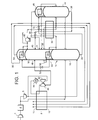
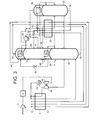
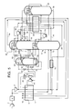
- Figures 1 to 5 all illustrate examples of the method and apparatus according to the invention in which a first auxiliary rectification column is used in conjunction with a double rectification column.
- a second auxiliary rectification column is used in addition to the first auxiliary rectification column.
- Figure 6 illustrates an example of the method and apparatus according to the invention in which a separation by partial vaporisation (or alternatively in a second auxiliary rectification column), is employed in conjunction with a double rectification column.
- Figure 7 illustrates an example of the method and apparatus according to the invention in which a triple rectification column is used.
- a flow of air is compressed in a main air compressor 2 which has an aftercooler (not shown) associated therewith, and is purified in an adsorption unit 4.
- the purification comprises removal from the air flow of impurities with relatively high boiling point, particularly water vapour and carbon dioxide, which would otherwise freeze in low temperature parts of the plant.
- the unit 4 may effect the purification by pressure swing adsorption or temperature swing adsorption.
- the unit 4 may additionally include one or more layers of catalyst for the removal of carbon-monoxide and hydrogen impurities. Such removal of carbon-monoxide and hydrogen impurities is described in EP-A-438 282.
- the construction and operation of such adsorptive purification units are well known and need not be described further herein.
- the air Downstream of the purification unit 4, the air is divided into a first air stream and a second air stream.
- the first air stream is further compressed by compression in a further compressor 6, having an aftercooler (not shown) associated therewith.
- the second air stream bypasses the further air compressor 6.
- the purified second air stream and the majority of the further compressed, purified, first air stream flow through a main heat exchanger 8 from its warm end 10 to its cold end 12. The air is thus cooled to a temperature suitable for its separation by rectification and hence leaves the cold end 12 of the main heat exchanger 8 in vaporous state.
- the compressed, vaporous, first air stream is separated in a double rectification column 14 comprising a higher pressure rectification column 16, a lower pressure rectification column 18, and a condenser-reboiler 20, of which the condensing passages (not shown) communicate with an upper region of the higher pressure rectification column 16 so as to condense nitrogen separated therein, and the reboiling passages (not shown) communicate with a lower region of the lower pressure rectification column 18.
- the first stream of vaporous compressed air enters the bottom of a lower region of the higher pressure rectification column 16.
- the higher pressure rectification column 16 contains members (not shown) defining liquid-vapour contact surfaces so as to bring into intimate mass transfer relationship the vapour ascending the column with liquid nitrogen condensed in the condenser-reboiler 20. As a result, nitrogen is separated from the first stream of compressed, vaporous, air.
- the second stream of compressed, vaporous, air is introduced into the bottom of a lower region of the auxiliary rectification column 22.
- Nitrogen is separated from the air in the auxiliary rectification column 22 analogously to the manner in which it is separated in the higher pressure rectification column 16.
- the.column 22 is provided with liquid-vapour contact members (not shown).
- Nitrogen separated in the auxiliary rectification column 22 is condensed in a second further condenser 26. A part of the resulting condensed nitrogen is returned to the further rectification column 22 so as to provide reflux for this column.
- a stream of oxygen-enriched liquid is withdrawn from the bottom of the lower region of the higher pressure rectification column 16 through an outlet 28, flows through a further heat exchanger 30, thereby being sub-cooled, passes through a throttling valve 32, and is introduced into the second further condenser 26 so as to condense by indirect heat exchange the nitrogen separated in the auxiliary rectification column 22.
- the stream of oxygen-enriched liquid is partially vaporised.
- a flow of resulting vapour is introduced through an inlet 34, and a flow of residual liquid is introduced through an inlet 36, into the lower pressure rectification column, 18 for separation therein.
- a flow of oxygen-enriched liquid is withdrawn from the bottom of a lower region of the auxiliary rectification column 22 through an outlet 38, is sub-cooled by passage through the heat exchanger 30, is reduced in pressure by passage through a throttling valve 39 and is introduced into the lower pressure rectification column 18 through an inlet 40 for separation therein.
- Another stream for separation in the lower pressure rectification column 18 is formed by withdrawing a part of the further compressed first air stream upstream of the warm end 10 of the main heat exchanger 8, compressing it to a yet higher pressure in a booster-compressor 42, cooling the air so as to remove heat of compression therefrom in an aftercooler 44, further cooling this air stream by passage through the main heat exchanger 8 from its warm end 10, withdrawing the further cooled air stream from an intermediate region of the main heat exchanger 8 at a temperature in the order of 140K and expanding it with the performance of external work in a turbo-expander 46.
- the resultant expanded air stream is then introduced into the lower pressure rectification column 18 through an inlet 48.
- the turbo-expander 46 is driven by the booster-compressor 42 and, as shown in Figure 1, is coupled to the booster-compressor 42.
- the various streams that are introduced into the lower pressure rectification column 18 are separated therein in a manner analogous to the separation of the air in the higher pressure rectification column 16.
- Liquid-vapour contact members (not shown) are provided in the column 18 for this purpose.
- Nitrogen is withdrawn from the top of the lower pressure rectification column 18 and is condensed in the first further condenser 24. At least a part of the resulting condensate is employed as reflux in the lower pressure rectification column 18.
- An upward flow of vapour through the column 18 is created by boiling liquid in the reboiling passages (not shown) of the condenser-reboiler 20.
- This boiling is performed by indirect heat exchange with condensing nitrogen in the condensing passages (not shown) of the condenser-reboiler 20.
- a stream of oxygen-enriched liquid typically having an oxygen mole fraction in the order of 0.55 to 0.75, preferably between 0.65 and 0.72 is withdrawn from the bottom of the lower region of the lower pressure rectification column 18 through an outlet 50, is reduced in pressure by passage through a throttling valve 52, and is introduced into the condenser 24.
- the oxygen-enriched liquid is vaporised.
- the resulting vapour is withdrawn from the condenser 24 through an outlet 54, is warmed by passage through the heat exchanger 30, thereby providing some of the cooling necessary for the sub-cooling of streams therein, and is further warmed to approximately ambient temperature by passage through the main heat exchanger from its cold end 12 to its warm end 10.
- the oxygen-enriched stream may be vented from the warm end 10 of the main heat exchanger 8 as a waste product.
- a lower pressure nitrogen product stream is withdrawn from the top of the lower pressure rectification column and flows along a conduit 56 to a further heat exchanger 30.
- the lower pressure nitrogen stream is warmed by passage through the further heat exchanger 30, thereby providing some of the cooling necessary for the sub-cooling streams therein.
- the warmed lower pressure nitrogen stream flows from the heat exchanger 30 through the main heat exchanger 8 from its cold end 12 to its warm end 10 and is thereby warmed to approximately ambient temperature.
- the lower pressure nitrogen stream may, if desired, be further compressed.
- a higher pressure nitrogen product is withdrawn from the top of the higher pressure rectification column 16 and flows along a conduit 58 to the further heat exchanger 30. Similarly to the other nitrogen stream, it is warmed by passage through this heat exchanger and flows through the main heat exchanger 8 from its cold end 12 to its warm end 10, and may be taken as product at approximately ambient temperature. If desired the higher pressure nitrogen product may be further compressed.
- nitrogen condensate is formed in the condenser-reboiler 20 and in the first and second further condensers 24 and 26, respectively.
- the second further condenser 26 condenses nitrogen at a rate in excess of the requirements for reflux of the auxiliary rectification column 22.
- the excess nitrogen condensate is therefore exported to the double rectification column 14.
- the excess nitrogen condensate from the second further condenser 26 together with similar excess nitrogen condensate from the first further condenser is pumped by the pump 60 to supplement the liquid nitrogen reflux in the higher pressure rectification column 16.
- the condenser-reboiler 20 may produce liquid nitrogen in excess of the requirements for reflux of the higher pressure rectification column 16.
- the excess liquid nitrogen together with the excess liquid nitrogen produced in the second condenser 26 may be employed as reflux in the lower pressure rectification column 18.
- excess liquid nitrogen may be taken as product.
- the higher pressure rectification column 16 may be operated at a pressure of about 8.3 bar at its bottom, the lower pressure rectification column 18 at a pressure of about 3.8 bar at its bottom and the auxiliary rectification column 22 at a pressure of about 6.0 bar at its bottom.
- the waste oxygen-enriched stream has a mole fraction of oxygen equal to 0.622 (corresponding to 85% recovery of nitrogen), 71.5% of the air is supplied to the higher pressure rectification column 16 at a pressure of 8.25 bar, 17.5% of the air is supplied to the auxiliary rectification column 22 at a pressure of 6.0 bar, and 11% of the air is supplied to the lower pressure rectification column 18 from the turbo-expander 46 at a pressure of 3.9 bar. 60.5% the nitrogen product is taken from the higher pressure rectification column 16 and 39.5% from the lower pressure rectification column 18.
- the auxiliary rectification column 22 and its associated condenser 26 are omitted.
- the higher pressure and lower pressure rectification columns are operated at the same pressures as in the example above. All the air which had previously been sent to the auxiliary rectification column 22 is instead included in the air that flows into the higher pressure rectification column. Accordingly extra power is consumed in raising this fraction of the air to the pressure of the higher rectification column, ie some 17.6% of the total incoming air flow is provided at a pressure 2.25 bar higher than in the example above.
- the example according to the invention exhibits a lower total power consumption.
- the waste oxygen-enriched stream has a mole fraction of oxygen equal to 0.694 (corresponding to 89% recovery of nitrogen).
- the higher pressure rectification column 16 is operated with a pressure at its bottom of 9.1 bar
- the auxiliary rectification column 22 with a pressure at its bottom of 6.5 bar
- the lower pressure rectification column 18 with a pressure of 4.2 bar at its bottom.
- 44% of the nitrogen product is taken from the higher pressure rectification column 16 and 56% from the lower pressure rectification column.
- the nitrogen recovery has been increased, thereby enabling the plant size to be reduced, the total power. consumption has increased.
- the plant shown therein is generally similar to that shown in Figure 2 except that the entire feed air flow passes through the booster-compressor 42.
- the flow of air is divided intermediate the aftercooler 44 and the warm end 10 of the main heat exchanger 8.
- One part of the split air flow passes through the main heat exchanger 8 from its warm end 10 to its cold end 12 as the first air stream and enters the higher pressure rectification column 16.
- the other part of the split air flow is cooled to a temperature in the order of 140K in the main heat exchanger 8 and is expanded in the turbo-expander 46 which exhausts into the auxiliary rectification column 22.
- the plant shown therein is generally similar to that shown in Figure 1 with the following exceptions.
- some of the first air stream is, downstream of the main heat exchanger 8, partially or totally condensed in a condenser 70 and is introduced through an inlet 72 into an intermediate mass exchange region of the higher pressure rectification column 16.
- Second, no high pressure nitrogen product is taken in the vapour state from the top of the higher pressure rectification column 16. Instead, a stream of condensed liquid nitrogen is pumped from the top of the higher pressure rectification column 16 by a pump 74 through the further heat exchanger 30 and is vaporised in the heat exchanger 70 in indirect heat exchange relationship with the air condensing therein.
- the necessary cooling for the condensation of the air is provided.
- the pump 74 raises the pressure of the liquid nitrogen to a pressure above that at the top of the higher pressure rectification column 16.
- the vaporised nitrogen passes from the heat exchanger 70 and is warmed to approximately ambient temperature by passage through the main heat exchanger 8 from its cold end 12 to its warm end 10. This flow of nitrogen is taken as the high pressure nitrogen product.
- a third difference is that a liquid stream comprising oxygen and nitrogen, having approximately the same composition as air, is withdrawn from the higher pressure rectification column 16 through an outlet 76 at the same level as the inlet 72.
- the liquid mixture is sub-cooled by passage through the further heat exchanger 30, is passed through a throttling valve 78, and is introduced into the lower pressure rectification column 18 for separation.
- the plant shown therein and its operation are generally similar to that shown in Figure 4 with the general exception that the plant shown in Figure 5 includes an additional rectification column 80 provided with a reboiler 82 and a condenser 84 in order to supplement with impure liquid nitrogen the liquid nitrogen condensate formed in the condenser-reboiler 20 of the double rectification column 14.
- the plant shown in Figure 5 includes an additional rectification column 80 provided with a reboiler 82 and a condenser 84 in order to supplement with impure liquid nitrogen the liquid nitrogen condensate formed in the condenser-reboiler 20 of the double rectification column 14.
- the valve 78 communicates at its outlet side with the bottom of the column 80.
- a part of the resulting liquid collecting in the bottom of the column 80 is reboiled by the reboiler 82 to form an ascending vapour stream. Mass exchange takes place between the stream and a descending liquid reflux stream. As a result impure nitrogen vapour is formed at the top of the column 80. This nitrogen vapour typically contains from 5 to 15% by volume of oxygen. It is condensed in the condenser 84. A part of the condensate forms the reflux for the column 80, and the remainder passes through a throttling valve 86 and enters the lower pressure rectification column 18 to supplement the liquid reflux therein.
- a stream of oxygen-enriched liquid is withdrawn from the bottom of the rectification column 80, is reduced in pressure by passage through a throttling valve 88, and is employed to cool the condenser 84.
- the oxygen-enriched liquid stream is vaporised in the condenser 84 by indirect heat exchange with the condensing impure nitrogen.
- the resulting vapour is introduced into the lower pressure rectification column 18 through an inlet 90.
- the reboiler 82 is heated by a stream of nitrogen vapour withdrawn from the top of the higher pressure rectification column.
- the resulting condensate is returned as reflux to the top of the higher pressure rectification column 16.
- the effect of introducing the additional rectification column 80 into the plant shown in Figure 5, in comparison with the plant shown in Figure 4, is to enable a greater proportion of the nitrogen product to be taken from the higher pressure rectification column 16, or to enable an increased proportion of the air to be separated in the auxiliary rectification column 22 without loss of nitrogen recovery.
- the total power consumption can be reduced, either by reducing the work of "external" compression of the nitrogen or by reducing the work of compression of the air.
- FIG. 6 the plant shown therein has a number of similarities to that shown in Figure 1, employing an analogous arrangement of compressors 2, 6, and 42 and turbo-expander 46, and an analogous purification unit 4, main heat exchanger 8 and double rectification column 14.
- the auxiliary rectification column 22 is omitted and there is therefore no passage through the main heat exchanger 8 for a stream of air at the operating pressure of the rectification column 22.
- the stream of oxygen-enriched liquid which is taken from the bottom of the higher pressure rectification column 16 is flashed through a throttling valve to form a mixture of flash gas and residual liquid, the mixture is separated in a phase separator, and the residual liquid is partially reboiled in order to form liquid and vapour streams that are fed to the double rectification column 14. Accordingly, the stream of oxygen-enriched liquid taken from the outlet 28 of the higher pressure rectification column 16, is sub-cooled in a higher temperature section of the further heat exchanger 30.
- the further heat exchanger 30 has higher temperature and lower temperature sections which are separate from one another, although they could form part of a single unit.
- the sub-cooled oxygen-enriched liquid is flashed through a throttling valve 132 into a phase separator 134 in which the resulting flash gas is separated from residual liquid.
- the residual liquid is partially vaporised in a vaporiser 136.
- the vapour phase in the phase separator 134 consists of impure nitrogen typically containing from 10 to 15% by volume of oxygen. A flow of this nitrogen is withdrawn from the top of the phase separator 134 and is condensed in a condenser 138.
- the resulting condensate is divided into four separate streams.
- a first of these streams is sub-cooled by passage through the lower temperature section of the further heat exchanger 30, is reduced in pressure by passage through a throttling valve 140 and is introduced into the lower pressure rectification column 18 as an impure liquid nitrogen reflux stream.
- a second stream of the nitrogen condensate from the condenser 138 is returned to the phase separator 134.
- the third and fourth streams are pumped by a pump 146 into an intermediate mass exchange region of the higher pressure rectification column 16, the third stream being warmed by passage through the higher temperature section of the further heat exchanger 30 and the fourth stream bypassing the heat exchanger 30.
- Introduction of the third and fourth streams into the higher pressure rectification column 16 helps to enhance the liquid-vapour ratio in the lower region of the column 16, thereby enabling more nitrogen to be taken as product from the higher pressure rectification column 16.
- Heating for the vaporiser 136 is provided by a stream of nitrogen vapour withdrawn from the top of the higher pressure rectification column 16.
- the nitrogen is condensed as a result of its indirect heat exchange with the vaporising liquid in the vaporiser 136.
- the nitrogen condensate is returned to the top of the rectification column 16 as reflux.
- a stream of oxygen-enriched liquid is withdrawn from the bottom of the phase separator 134, is reduced in pressure and temperature by passage through a throttling valve 156 and is employed to provide the necessary cooling for the condenser 138.
- the oxygen-enriched liquid stream is at least partially vaporised.
- the resulting stream is introduced into the lower pressure rectification column 18 through an inlet 158.
- Analogous product streams are taken to those of the plant shown in Figure 1, with the exception that the high pressure nitrogen stream withdrawn through the outlet 58 bypasses the further heat exchanger 30.
- phase separator 134 may be replaced by a further installation column typically containing up to 15 theoretical trays.
- the plant shown in Figure 6 enables the higher pressure rectification column 16 to be operated at a pressure corresponding to those at which this column is operated in the plants shown in Figures 4 and 5 without loss of nitrogen recovery. Further, a similar proportion of the nitrogen product to that in the plant shown in Figure 5 may be taken from the higher pressure rectification column. However, with the omission of the auxiliary rectification column 22, more work needs to be expended in compressing the incoming air.
- a flow of air is compressed in a main compressor 202, is cooled in an aftercooler (not shown) and has water vapour, carbon dioxide and other impurities removed therefrom in a purification unit 204.
- the purification unit 204 and its operation are analogous to the purification unit 4 described here and above with reference to Figure 1.
- the flow of purified air is divided into two streams. A first of these streams flows through a main heat exchanger 208 from its warm end 210 to its cold end 212 and is thereby cooled to a temperature suitable for its separation by rectification.
- This separation is performed in a triple rectification column 214, comprising a higher pressure rectification column 216, a lower pressure rectification column 218, an intermediate pressure rectification column 220, a first condenser-reboiler 222 having condensing passages communicating with an upper region of the higher pressure rectification column 216 and reboiling passages communicating with a lower region of the intermediate pressure rectification column 220, and a second condenser-reboiler 224 having condensing passages communicating with an upper region of the intermediate pressure rectification column 220 and reboiling passages communicating with the lower region of the lower pressure rectification column 218.
- the upper region of the lower pressure rectification column 218 communicates with a condenser 226.
- the rectification columns 216, 218 and 220 all contain liquid-vapour contact members (not shown) to enable mass exchange to take place between ascending vapour and descending liquid.
- the liquid-vapour contact members may be distillation trays, or packing such as structured packing.
- the first air stream is introduced into a bottom region of the higher pressure rectification column 216 and has nitrogen and has nitrogen separated from it.
- the nitrogen is condensed in the first condenser reboiler 222 and all the resulting condensate is returned to the column 216 as reflux.
- a stream of oxygen-enriched liquid is withdrawn from the bottom of the higher pressure rectification column 216 through an outlet 227, is sub-cooled in a further heat exchanger 228, is reduced in pressure by passage through a throttling valve 230 and is introduced into the bottom of the intermediate pressure rectification column 220.
- the liquid in the bottom of the column 220 is partially reboiled by the first condenser-reboiler 222. Impure nitrogen is separated from this vapour in the column 220.
- a stream of impure nitrogen is withdrawn from an upper region of the intermediate pressure rectification column 220, this stream typically containing about 10% by volume of oxygen.
- the impure nitrogen stream is condensed in the second condenser reboiler 224.
- a first part of the stream is returned to the top of the intermediate pressure rectification column 220 as reflux.
- a second part of the stream is passed by a pump 234 into an intermediate mass exchange region of the higher pressure rectification column 216 and thereby provides reflux for the lower region of the column 216.
- a stream of oxygen-enriched liquid is withdrawn from the bottom of the intermediate pressure rectification column 220, is reduced in pressure by passage through a throttling valve 240 and is introduced into the lower pressure rectification column 218 for separation therein.
- a further stream of fluid for separation in the column 218 is formed from the second stream of purified air.
- This stream is further compressed in a compressor 242, is cooled in an aftercooler 244, is further cooled by passage through the main heat exchanger 208 to a temperature of about 135K, is taken from the heat exchanger 208 at this temperature, is expanded with the performance of external work in a turbo-expander 248 and is introduced into the lower pressure rectification column 218 for separation therein.
- the streams introduced into the lower pressure rectification column 218 are separated into relatively pure nitrogen containing less than 0.1 % by volume of impurities at the top of the column 218 and an impure liquid oxygen fraction typically containing from 55 to 70% by volume of oxygen at the bottom of the column.
- a first stream of nitrogen vapour is withdrawn from the top of the column 218, is condensed in the condenser 226 and is returned to the column 218 as reflux.
- a stream of the oxygen-enriched liquid is withdrawn from the bottom of the rectification column 218, and is partially reboiled in the second condenser-reboiler 224.
- the partially reboiled stream has liquid disengaged from attendant vapour in a phase separator 250.
- the resulting vapour phase is returned to the bottom of the column 218.
- a stream of the residual liquid is sub-cooled by passage through a heat exchanger 254, is reduced in pressure by passage through a throttling valve 256 and is introduced into the condenser 226 so as to provide the cooling necessary for the condensation of nitrogen therein.
- the oxygen-enriched liquid stream is vaporised.
- the resulting oxygen-enriched vapour flows through the heat exchangers 254 and 228 and thereby provides some of the necessary cooling for these heat exchangers.
- the oxygen-enriched vapour flows from the heat exchanger 228 and passes through the main heat exchanger 208 from its cold end 212 to its warm end 210. It is typically vented from the plant to the atmosphere as a waste stream.
- a second stream of nitrogen is withdrawn from the lower pressure rectification column 218 as product, and flows through the heat exchangers 254, 228 and 208, in sequence, thereby providing the rest of the cooling for the heat exchanger 254 and 228.
- a low pressure nitrogen product stream is thus formed at approximately ambient temperature.
- a high pressure nitrogen product stream is taken from the top of the higher pressure rectification column 216 through an outlet 262 and is warmed to approximately ambient temperature by passage through the main heat exchanger 208.
- the condenser 226 condenses more nitrogen than is needed as reflux in the low pressure rectification column 218.
- the excess liquid nitrogen reflux is passed by a pump 264 into the higher pressure rectification column 216 to supplement the reflux therein.
- the pressure at the top of the higher pressure rectification column 216 is about 10.5 bar, at the top of the lower pressure rectification column 218 is about 4 bar, and at the top of the intermediate pressure rectification column 220 is about 6.5 bar.
- the turbo-expander 248 has an inlet pressure of 13.6 bar. Approximately 80% of the nitrogen product is taken through the outlet 262 from the higher pressure rectification column 216. The nitrogen recovery is 86%.
Landscapes
- Engineering & Computer Science (AREA)
- Physics & Mathematics (AREA)
- Mechanical Engineering (AREA)
- Thermal Sciences (AREA)
- General Engineering & Computer Science (AREA)
- Separation By Low-Temperature Treatments (AREA)
Applications Claiming Priority (2)
| Application Number | Priority Date | Filing Date | Title |
|---|---|---|---|
| GBGB9724787.8A GB9724787D0 (en) | 1997-11-24 | 1997-11-24 | Production of nitrogen |
| GB9724787 | 1997-11-24 |
Publications (2)
| Publication Number | Publication Date |
|---|---|
| EP0921367A2 true EP0921367A2 (de) | 1999-06-09 |
| EP0921367A3 EP0921367A3 (de) | 1999-09-29 |
Family
ID=10822542
Family Applications (1)
| Application Number | Title | Priority Date | Filing Date |
|---|---|---|---|
| EP98309443A Withdrawn EP0921367A3 (de) | 1997-11-24 | 1998-11-18 | Herstellung von Stickstoff |
Country Status (4)
| Country | Link |
|---|---|
| US (1) | US6257019B1 (de) |
| EP (1) | EP0921367A3 (de) |
| GB (1) | GB9724787D0 (de) |
| TW (1) | TW512218B (de) |
Cited By (6)
| Publication number | Priority date | Publication date | Assignee | Title |
|---|---|---|---|---|
| EP1043556A1 (de) * | 1999-04-09 | 2000-10-11 | L'air Liquide, Societe Anonyme Pour L'etude Et L'exploitation Des Procedes Georges Claude | Hochdruckverfahren zur Tieftemperaturluftzerleggung und Vorrichtung |
| US6397631B1 (en) | 2001-06-12 | 2002-06-04 | Air Products And Chemicals, Inc. | Air separation process |
| FR2830928A1 (fr) * | 2001-10-17 | 2003-04-18 | Air Liquide | Procede de separation d'air par distillation cryogenique et une installation pour la mise en oeuvre de ce procede |
| DE19933558C5 (de) * | 1999-07-16 | 2010-04-15 | Linde Ag | Dreisäulenverfahren und -vorrichtung zur Tieftemperaturzerlegung von Luft |
| EP3521739A1 (de) * | 2018-02-02 | 2019-08-07 | Linde Aktiengesellschaft | Verfahren und vorrichtung zur gewinnung von druckstickstoff durch tieftemperaturzerlegung von luft |
| WO2020169257A1 (de) | 2019-02-22 | 2020-08-27 | Linde Gmbh | Verfahren und anlage zur tieftemperaturzerlegung von luft |
Families Citing this family (15)
| Publication number | Priority date | Publication date | Assignee | Title |
|---|---|---|---|---|
| DE10045128A1 (de) * | 2000-09-13 | 2002-03-21 | Linde Ag | Verfahren und Vorrichtung zur Erzeugung hoch reinen Stickstoffs durch Tieftemperatur-Luftzerlegung |
| US7284395B2 (en) * | 2004-09-02 | 2007-10-23 | Praxair Technology, Inc. | Cryogenic air separation plant with reduced liquid drain loss |
| GB0422635D0 (en) * | 2004-10-12 | 2004-11-10 | Air Prod & Chem | Process for the cryogenic distillation of air |
| DE102009048456A1 (de) * | 2009-09-21 | 2011-03-31 | Linde Aktiengesellschaft | Verfahren und Vorrichtung zur Tieftemperaturzerlegung von Luft |
| EP2312247A1 (de) * | 2009-10-09 | 2011-04-20 | Linde AG | Verfahren und Vorrichtung zur Gewinnung von flüssigem Stickstoff durch Tieftemperatur-Luftzerlegung |
| US9726427B1 (en) * | 2010-05-19 | 2017-08-08 | Cosmodyne, LLC | Liquid nitrogen production |
| US8991209B2 (en) * | 2010-12-13 | 2015-03-31 | L'air Liquide Societe Anonyme Pour L'etude Et L'exploitation Des Procedes Georges Claude | Process and installation for producing high-pressure nitrogen |
| US20150316317A1 (en) * | 2012-12-27 | 2015-11-05 | Linde Aktiengesellschaft | Method and device for low-temperature air separation |
| US10314249B2 (en) * | 2014-12-10 | 2019-06-11 | The Boeing Company | Systems and methods of inducing rainfall |
| WO2021242309A1 (en) | 2020-05-26 | 2021-12-02 | Praxair Technology, Inc. | Enhancements to a dual column nitrogen producing cryogenic air separation unit |
| WO2021242308A1 (en) | 2020-05-26 | 2021-12-02 | Praxair Technology, Inc. | Enhancements to a dual column nitrogen producing cryogenic air separation unit |
| WO2021242307A1 (en) | 2020-05-28 | 2021-12-02 | Praxair Technology, Inc. | Enhancements to a dual column nitrogen producing cryogenic air separation unit |
| US11674750B2 (en) | 2020-06-04 | 2023-06-13 | Praxair Technology, Inc. | Dual column nitrogen producing air separation unit with split kettle reboil and integrated condenser-reboiler |
| CN112066644A (zh) * | 2020-09-18 | 2020-12-11 | 乔治洛德方法研究和开发液化空气有限公司 | 一种生产高纯氮和低纯氧的方法和装置 |
| CN113606866A (zh) * | 2021-08-06 | 2021-11-05 | 苏州市兴鲁空分设备科技发展有限公司 | 一种空气分离制取氮气的装置和方法 |
Family Cites Families (11)
| Publication number | Priority date | Publication date | Assignee | Title |
|---|---|---|---|---|
| US4604117A (en) * | 1984-11-15 | 1986-08-05 | Union Carbide Corporation | Hybrid nitrogen generator with auxiliary column drive |
| US5006139A (en) * | 1990-03-09 | 1991-04-09 | Air Products And Chemicals, Inc. | Cryogenic air separation process for the production of nitrogen |
| US5137559A (en) * | 1990-08-06 | 1992-08-11 | Air Products And Chemicals, Inc. | Production of nitrogen free of light impurities |
| US5123947A (en) * | 1991-01-03 | 1992-06-23 | Air Products And Chemicals, Inc. | Cryogenic process for the separation of air to produce ultra high purity nitrogen |
| US5233838A (en) * | 1992-06-01 | 1993-08-10 | Praxair Technology, Inc. | Auxiliary column cryogenic rectification system |
| FR2701313B1 (fr) * | 1993-02-09 | 1995-03-31 | Air Liquide | Procédé et installation de production d'azote ultra-pur par distillation d'air. |
| US5341646A (en) * | 1993-07-15 | 1994-08-30 | Air Products And Chemicals, Inc. | Triple column distillation system for oxygen and pressurized nitrogen production |
| US5402647A (en) * | 1994-03-25 | 1995-04-04 | Praxair Technology, Inc. | Cryogenic rectification system for producing elevated pressure nitrogen |
| GB9505645D0 (en) * | 1995-03-21 | 1995-05-10 | Boc Group Plc | Air separation |
| US5682762A (en) * | 1996-10-01 | 1997-11-04 | Air Products And Chemicals, Inc. | Process to produce high pressure nitrogen using a high pressure column and one or more lower pressure columns |
| US5761927A (en) * | 1997-04-29 | 1998-06-09 | Air Products And Chemicals, Inc. | Process to produce nitrogen using a double column and three reboiler/condensers |
-
1997
- 1997-11-24 GB GBGB9724787.8A patent/GB9724787D0/en not_active Ceased
-
1998
- 1998-11-18 EP EP98309443A patent/EP0921367A3/de not_active Withdrawn
- 1998-11-24 US US09/198,682 patent/US6257019B1/en not_active Expired - Fee Related
- 1998-12-23 TW TW087121535A patent/TW512218B/zh active
Cited By (9)
| Publication number | Priority date | Publication date | Assignee | Title |
|---|---|---|---|---|
| EP1043556A1 (de) * | 1999-04-09 | 2000-10-11 | L'air Liquide, Societe Anonyme Pour L'etude Et L'exploitation Des Procedes Georges Claude | Hochdruckverfahren zur Tieftemperaturluftzerleggung und Vorrichtung |
| DE19933558C5 (de) * | 1999-07-16 | 2010-04-15 | Linde Ag | Dreisäulenverfahren und -vorrichtung zur Tieftemperaturzerlegung von Luft |
| US6397631B1 (en) | 2001-06-12 | 2002-06-04 | Air Products And Chemicals, Inc. | Air separation process |
| EP1271081A3 (de) * | 2001-06-12 | 2003-02-12 | Air Products And Chemicals, Inc. | Verfahren zur luftzerlegung |
| FR2830928A1 (fr) * | 2001-10-17 | 2003-04-18 | Air Liquide | Procede de separation d'air par distillation cryogenique et une installation pour la mise en oeuvre de ce procede |
| WO2003033978A3 (fr) * | 2001-10-17 | 2003-10-02 | Air Liquide | Procede de separation d'air par distillation cryogenique et une installation pour la mise en oeuvre de ce procede |
| US7219514B2 (en) | 2001-10-17 | 2007-05-22 | L'Air Liquide, Société Anonyme á Directoire et Conseil de Surveillance our l'Etude et l'Exploitation des Procédés Georges Claude | Method for separating air by cryogenic distillation and installation therefor |
| EP3521739A1 (de) * | 2018-02-02 | 2019-08-07 | Linde Aktiengesellschaft | Verfahren und vorrichtung zur gewinnung von druckstickstoff durch tieftemperaturzerlegung von luft |
| WO2020169257A1 (de) | 2019-02-22 | 2020-08-27 | Linde Gmbh | Verfahren und anlage zur tieftemperaturzerlegung von luft |
Also Published As
| Publication number | Publication date |
|---|---|
| EP0921367A3 (de) | 1999-09-29 |
| US6257019B1 (en) | 2001-07-10 |
| GB9724787D0 (en) | 1998-01-21 |
| TW512218B (en) | 2002-12-01 |
Similar Documents
| Publication | Publication Date | Title |
|---|---|---|
| US6257019B1 (en) | Production of nitrogen | |
| CA2045738C (en) | Cryogenic air separation system with dual feed air side condensers | |
| US5577394A (en) | Air separation | |
| EP0674144A1 (de) | Kryogenisches Rektifikationsverfahren zur Herstellung von Hochdruckstickstoff | |
| US5287704A (en) | Air separation | |
| CN1057380C (zh) | 低温空气分离方法和设备 | |
| US5485729A (en) | Air separation | |
| KR20220166824A (ko) | 공기의 극저온 분류 공정, 공기 분류 플랜트 및 적어도 2개의 공기 분류 플랜트로 구성된 통합 시스템 | |
| US5893276A (en) | Air separation | |
| US5582031A (en) | Air separation | |
| EP0881446B1 (de) | Kryogenisches Verfahren mit Doppelsäure und externem Verdämpfer-Kondensator für eine Sauerstoff- und Stickstoffmischung | |
| EP1243883A1 (de) | Luftzerlegung | |
| US5303556A (en) | Single column cryogenic rectification system for producing nitrogen gas at elevated pressure and high purity | |
| US6141989A (en) | Air separation | |
| US4717409A (en) | Liquid vapor contact method and apparatus | |
| US6082137A (en) | Separation of air | |
| EP0752566B1 (de) | Lufttrennung | |
| AU706680B2 (en) | Air separation | |
| US6305191B1 (en) | Separation of air | |
| CA2094530C (en) | Cryogenic rectification system with dual heat pump | |
| US5386691A (en) | Cryogenic air separation system with kettle vapor bypass | |
| EP0828124B1 (de) | Lufttrennung | |
| US5862680A (en) | Air separation | |
| US6170291B1 (en) | Separation of air | |
| US5692397A (en) | Air separation |
Legal Events
| Date | Code | Title | Description |
|---|---|---|---|
| PUAI | Public reference made under article 153(3) epc to a published international application that has entered the european phase |
Free format text: ORIGINAL CODE: 0009012 |
|
| AK | Designated contracting states |
Kind code of ref document: A2 Designated state(s): BE DE ES FR GB IT NL |
|
| AX | Request for extension of the european patent |
Free format text: AL;LT;LV;MK;RO;SI |
|
| PUAL | Search report despatched |
Free format text: ORIGINAL CODE: 0009013 |
|
| AK | Designated contracting states |
Kind code of ref document: A3 Designated state(s): AT BE CH CY DE DK ES FI FR GB GR IE IT LI LU MC NL PT SE |
|
| AX | Request for extension of the european patent |
Free format text: AL;LT;LV;MK;RO;SI |
|
| 17P | Request for examination filed |
Effective date: 20000309 |
|
| AKX | Designation fees paid |
Free format text: BE DE ES FR GB IT NL |
|
| 17Q | First examination report despatched |
Effective date: 20010827 |
|
| STAA | Information on the status of an ep patent application or granted ep patent |
Free format text: STATUS: THE APPLICATION IS DEEMED TO BE WITHDRAWN |
|
| 18D | Application deemed to be withdrawn |
Effective date: 20021207 |