EP0921385A2 - Dispositif d'obturation d'un tube pour un essai sous pression - Google Patents
Dispositif d'obturation d'un tube pour un essai sous pression Download PDFInfo
- Publication number
- EP0921385A2 EP0921385A2 EP98250393A EP98250393A EP0921385A2 EP 0921385 A2 EP0921385 A2 EP 0921385A2 EP 98250393 A EP98250393 A EP 98250393A EP 98250393 A EP98250393 A EP 98250393A EP 0921385 A2 EP0921385 A2 EP 0921385A2
- Authority
- EP
- European Patent Office
- Prior art keywords
- press fitting
- pressure piece
- bolt
- section
- collar
- Prior art date
- Legal status (The legal status is an assumption and is not a legal conclusion. Google has not performed a legal analysis and makes no representation as to the accuracy of the status listed.)
- Granted
Links
- 238000012360 testing method Methods 0.000 title claims description 9
- 238000007789 sealing Methods 0.000 claims abstract description 43
- 239000011324 bead Substances 0.000 claims description 12
- 230000000295 complement effect Effects 0.000 claims description 2
- 230000006835 compression Effects 0.000 claims description 2
- 238000007906 compression Methods 0.000 claims description 2
- 238000006073 displacement reaction Methods 0.000 claims description 2
- 238000009423 ventilation Methods 0.000 description 4
- 238000010276 construction Methods 0.000 description 2
- 230000000694 effects Effects 0.000 description 2
- 238000012549 training Methods 0.000 description 2
- 230000009286 beneficial effect Effects 0.000 description 1
- 238000003780 insertion Methods 0.000 description 1
- 230000037431 insertion Effects 0.000 description 1
- 238000000034 method Methods 0.000 description 1
- 238000013022 venting Methods 0.000 description 1
Images


Classifications
-
- G—PHYSICS
- G01—MEASURING; TESTING
- G01M—TESTING STATIC OR DYNAMIC BALANCE OF MACHINES OR STRUCTURES; TESTING OF STRUCTURES OR APPARATUS, NOT OTHERWISE PROVIDED FOR
- G01M3/00—Investigating fluid-tightness of structures
- G01M3/02—Investigating fluid-tightness of structures by using fluid or vacuum
- G01M3/022—Test plugs for closing off the end of a pipe
Definitions
- the invention relates to a device for closing a pipe Carrying out a pressure test according to the preamble of patent claim 1.
- connection arrangement one with an outer profile provided tubular connecting piece known with a connector.
- the known connection arrangement has an annular intermediate piece, the one end one pushed sideways on the connecting piece, over the External profile absorbing tractive and / or compressive forces Projection and at the other end has a receptacle for the connector. Is to the receptacle with an internal thread and the connector with a appropriately trained external thread.
- the connector has a through vent hole, which is by means of a vent screw is lockable.
- a somewhat differently designed device for closing a pipeline is out the CH 687412 A 5 known.
- This closure has one in one with one Ring bead provided press fitting insertable sealing piston carrier on the the side facing away from the press fitting with a radially outward extending collar is provided.
- This acts with a radially inward effect extending collar of a mounting sleeve together, which radially on the Press fitting can be pushed on.
- the mounting sleeve lies after the radial Slip on a larger than 180 ° circumferential area on the ring bead of the press fitting.
- the sealing piston carrier is with a vent hole provided, which can be closed with a vent screw.
- the cone-like trained section of the sealing piston carrier acts with the standard in Ring bead of the press fitting arranged sealing ring together.
- the object of the invention is a device for closing a pipeline to carry out a pressure test that is independent of the Tolerance pairing press fitting / closure element a secure seal also for higher pressures ( ⁇ 10 bar) and larger dimensions ( ⁇ 2 ”) guaranteed.
- the Nut the sealing ring forced to spread, and so until it seals securely comes to rest on the inner wall of the cylindrical section of the press fitting
- the sealing ring comes through a adjustable compression under tension to the system, so that too Shape deviations and unfavorable tolerance pairings can thus be bridged.
- a radially extending through the collar itself extending bore can be arranged in order to prevent rotation between the pressure piece and the bolt.
- Training as an elongated hole is required so that when turning the nut pressure piece and bolt can move relative to each other to the desired spread of the To effect sealing rings.
- the elongated hole can also be arranged in the pressure piece and the pin is in a blind hole in the bolt driven in.
- the anti-rotation device can also be designed to be detachable as a threaded pin be screwed into a corresponding threaded hole.
- the insurance the closure element against axial pressing out takes place in a known manner via a clamp or fastening sleeve that can be pushed radially onto the press fitting.
- the mounting sleeve has one Internal thread section, which with an applied to the pressure piece External thread section cooperates.
- the bracket indicates Pin element on that in an annular recess of the pressure piece can be inserted.
- the mounting sleeve or the bracket still has the additional advantage that it acts as a counterforce to the expanded sealing ring act so that the cylindrical section of the press fitting lying in the sealing area is not deformed in an inadmissible manner.
- the securing element against axial pressing out of the closure element as a clamp with two to form interconnectable half-shells.
- the half shells have one Inner contour, which is the outer contour formed in the sealing area of the press fitting corresponds.
- the actual securing takes place via a arranged on the input side radially inwardly extending collar so that in the event of failure the Mother comes to rest on the inside of the collar and pushing the Closure element prevented.
- the connection of the two half shells can be done via Screws or a joint or via a slide-on sleeve, wherein the latter is additionally secured axially.
- Figure 1 is a longitudinal section of an inventive device for closing a pipeline for performing a pressure test shown.
- a Press fitting 1 arranged, the cylindrical section at least on one side 2 and then has an annular bead 3 thereon.
- this ring bead 3 is at Connection of a further line a seal arranged.
- the device according to the invention has the following elements: A bolt 4, which is axially displaceable a pressure piece 5 is arranged, which with a on the bolt 4 screw-on nut 6 interacts.
- the sealing takes place on a the bolt 4 arranged sealing ring 7 and the ventilation via a in the bolt 4th screw-in vent screw 8.
- the sealing ring 7 is in this Embodiment designed as a flat ring.
- a radial on the Press fitting 1 clip 9 can be provided. The details are in the following Figures 2-7 explained.
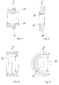
- the bolt 4 shown in Figure 2 has a collar 10 on the front, on which the Sealing ring 7 axially comes to rest.
- a paragraph closes a cylindrical trained section 11 on which the pressure piece 5 is axially displaceable can be arranged. Separated by a groove 12 connects to the cylindrical Section 11 to a threaded section 13.
- the nut 6 can be screwed onto this.
- the bolt 4 has a vent hole 14 which merges into a channel 15 and a subsequent threaded bore 16.
- Threaded bore 16 is the vent screw 8 shown in FIG. 3 screwable.
- the vent screw has an external thread section 17 and for turning a collar 19 provided with knurling 18.
- the other The end is designed as a cone 20, which closes with the channel 15 of the bolt 4 cooperates.
- the pressure piece 5 shown in Figure 4 is an essentially cylindrical one Hollow body formed with an outwardly extending collar 21. This Collar 21 comes to rest on the end face of the annular bead 3 of the press fitting 1. On the side facing away from the press fitting 1 there is an annular on the pressure piece 5 Recess 22 is provided, in which a correspondingly designed pin element 23 of the clip 9 can be inserted.
- the nut 6 shown in FIG. 5 faces the pressure piece 5 Side a chamfer 24 on the front area 25 of the pressure piece 5th is adjusted.
- the Nut 6 is provided with a correspondingly designed threaded bore 26.
- the mantle area of the nut with a knurling 29 Mistake.
- the bracket 9 shown in Figures 6 and 7 has an inner contour that the Outer contour of the press fitting 1 is adjusted.
- the circumference of the bracket 9 is over cut off a certain area and forms a mouth 27, the clear width 28 is always somewhat larger than the corresponding outer contour of the press fitting 1 or the pressure piece 5.
- a bias in the sealing ring 7 can be generated, so that a secure seal is guaranteed.
- the ventilation screw 8 in the bolt 4th screwed in until the cone 20 comes into sealing contact After that the Pressure test carried out.
- a radial on the Press fitting 1 clip 9 can be used. After insertion the bolt 4 in the press fitting 1 and sliding the clip 9, the bolt 4th axially moved back by hand until the annular groove 22 of the pressure piece 5 and that Pin element 23 of the clamp 9 are pushed into one another. This then creates the necessary anti-rotation device. so that, as previously explained, the Nut 6 can be rotated to spread the sealing ring 7.
- a second embodiment is shown in a longitudinal section in FIG.
- the Closure device designed according to the invention has the following elements.
- the Sealing takes place via a sealing ring 33 arranged on the bolt 30, which in this embodiment is designed as a round ring.
- a fastening sleeve 40 which can be pushed radially onto the press fitting 1 be provided. The details are shown in the following FIGS. 9-12 explained.
- the bolt 30 shown in FIG. 9 has a collar 44 on the end face, on which the Sealing ring 33 comes to rest.
- a paragraph closes a cylindrical trained section 45 on which the pressure port 31 is axially displaceable can be arranged. Separated by a groove 49 connects to the cylindrical Section 45 to a threaded section 46. On this is the knurled 29th provided nut 32 screwable.
- the venting takes place via a bore 34 extending through the bolt 30.
- This bore has a threaded section 35 on the input side, into which one here Connection cable, not shown, can be screwed in.
- the large cross section of the Hole 34 was chosen deliberately in order to test the pipeline to be able to fill quickly.
- the required ventilation is usually called Branch arranged in the connection line.
- the pressure piece 31 is secured against rotation on the Bolt 30 arranged.
- the pressure piece 31 (FIG. 10) has a radial end outwardly extending collar 36. Extends radially through this collar 36 a hole 37 through which an anti-rotation, here z. B. a pin 38 ( Figure 8) is insertable.
- the head end of the pin 38 engages to prevent rotation a recess 39 arranged in the bolt 30 and designed as an elongated hole (FIG. 9) on.
- the length of the slot corresponds to the required relative Displacement between bolt 30 and pressure piece 31, around the sealing ring 33 to spread accordingly.
- Slidable fastening sleeve 40 is provided to the closure element when pressing before To ensure that it is pressed out. This has one Internal thread section 41, which is arranged with a on the pressure piece 31 External thread section 42 cooperates.
- Pressure piece 31 and fastening sleeve 40 acts on the pressure piece 31 arranged Paragraph 48 ( Figure 10) as a stop, so that the pressure piece 31 on the front side of the Ring bead 3 of the press fitting 1 comes to the plant.
- the standard in the ring bead 3 of the press fitting 1 arranged sealing ring 43 can also be used as a seal are, but ultimately the arranged on the pressure piece 31 sealing ring 33 for the seal is decisive.
- the fastening sleeve 40 shown in FIGS. 11 and 12 has one Inner contour, which is adapted to the outer contour of the press fitting 1. This applies to one for the bevel 50 and for the dimension of the bore 51, which is slightly larger than the outer diameter of the cylindrical portion 2 of the press fitting 1.
- the fastening sleeve 40 is circumferentially in the thread-free section over a cut certain area and forms a mouth 52, the clear width always is slightly larger than the corresponding outer contour of the press fitting 1.
- FIG 13 is a longitudinal section and in Figure 14 in a half-sided cross section and a half-sided view of a third embodiment.
- the Closure device designed according to the invention has the following elements.
- Sealing takes place as in FIGS. 1 and 8 already explained, via a sealing ring 33 arranged on the bolt 55, which is also in this embodiment is designed as a round ring.
- the bolt 55 has on the front side a collar 66 on which the sealing ring 33 axially comes to rest.
- the anti-rotation device is designed somewhat differently.
- an elongated hole 58 is arranged and correspondingly one in the bolt 55 Blind hole 59.
- a pin 38 is driven into this blind hole 59, whose foot end protrudes into the slot 58.
- the bolt 55 has two on the end facing away from the press fitting 1 Flattenings 60, 60 'to be able to insert an open-end wrench.
- the two half shells 61, 62 have an inner contour that the outer contour of the press fitting 1 in Sealing area is adapted and a radially inward at one end extending collar 63 which is dimensioned such that it acts as a stop for the nut 57 serves if the closure element should be pushed out.
- the connection of the two half-shells 61, 62 is carried out via threaded bolts 64, 64 ', 64 ", 64"' on the Nuts 65 - 65 "'can be screwed on.
- the two half shells 61, 62 link together and secure with a hook lock.
- FIGS. 15, 16 show a variant of the embodiment according to FIGS. 13, 14 shown.
- the same reference numerals have been chosen for the same parts.
- the two half-shells 70, 71 not by screws and corresponding Tapped holes, but secured by a slide-on sleeve 72.
- this can be a Be a snap lock in which at least one radially displaceable bolt 73, 73 ' with its tip in an annular arranged on each half-shell 70, 71 Recess 74, 75 can engage.
- the snap lock shown here is only an example of an axial securing of the sleeve 72. Other types of axial securing are imaginable and practical.
- FIG. 17, 18 shows a further embodiment, which is a variant of that in FIG. 1 construction shown.
- the locking system is as before described from a bolt 80 which has a collar 81 on the end face, on which the Sealing ring 7 axially comes to rest.
- a pressure piece 82 which axially by means of the nut 6 on the cylindrical portion of the bolt 80 is slidably arranged.
- the pin 80 points to the press fitting 1 end portion facing away from a threaded portion 83.
- the bolt 80 is provided with a bore.
- Thrust piece 82 in the end region with an outwardly extending collar 84 Mistake.
- This collar 84 is a radially slidable on the press fitting 1
- Clip 85 slidable.
- This clip 85 is complementary to the collar 84 formed annular recess 86.
- the bracket 85 is with a Provide inner contour that is adapted to the outer contour of the press fitting 1.
- the clip 85 is circumferentially cut off over a certain area and forms a mouth, the clear width of which is always somewhat larger than the corresponding one Outer contour of the press fitting 1 or the pressure piece 82.
Landscapes
- Physics & Mathematics (AREA)
- General Physics & Mathematics (AREA)
- Pipe Accessories (AREA)
- Examining Or Testing Airtightness (AREA)
- Investigating Strength Of Materials By Application Of Mechanical Stress (AREA)
- Pipeline Systems (AREA)
Applications Claiming Priority (2)
| Application Number | Priority Date | Filing Date | Title |
|---|---|---|---|
| DE19755879A DE19755879C1 (de) | 1997-12-04 | 1997-12-04 | Vorrichtung zum Verschließen einer Rohrleitung zur Durchführung einer Druckprüfung |
| DE19755879 | 1997-12-04 |
Publications (3)
| Publication Number | Publication Date |
|---|---|
| EP0921385A2 true EP0921385A2 (fr) | 1999-06-09 |
| EP0921385A3 EP0921385A3 (fr) | 2000-01-26 |
| EP0921385B1 EP0921385B1 (fr) | 2004-12-22 |
Family
ID=7852096
Family Applications (1)
| Application Number | Title | Priority Date | Filing Date |
|---|---|---|---|
| EP98250393A Expired - Lifetime EP0921385B1 (fr) | 1997-12-04 | 1998-11-10 | Dispositif d'obturation d'un tube pour un essai sous pression |
Country Status (3)
| Country | Link |
|---|---|
| EP (1) | EP0921385B1 (fr) |
| AT (1) | ATE285570T1 (fr) |
| DE (2) | DE19755879C1 (fr) |
Cited By (1)
| Publication number | Priority date | Publication date | Assignee | Title |
|---|---|---|---|---|
| EP2049879A4 (fr) * | 2006-08-07 | 2010-11-03 | Car Ber Investments Inc | Dispositif et procédé pour isoler ou tester un segment de tuyau comportant un renfort axial |
Families Citing this family (1)
| Publication number | Priority date | Publication date | Assignee | Title |
|---|---|---|---|---|
| DE102020129583A1 (de) | 2020-11-10 | 2022-05-12 | SABUG GmbH | Verschlussvorrichtung zum Anschließen eines Druckprüfgerätes, Klemmvorrichtung zum Fixieren eines Verschluss- oder Muffenstopfens sowie System und Verfahren zur Dichtigkeitsüberprüfung |
Citations (2)
| Publication number | Priority date | Publication date | Assignee | Title |
|---|---|---|---|---|
| CH681652A5 (fr) | 1990-03-30 | 1993-04-30 | Nussbaum & Co Ag R | |
| CH687412A5 (de) | 1994-04-12 | 1996-11-29 | Rudolf Keller | Verschluss. |
Family Cites Families (5)
| Publication number | Priority date | Publication date | Assignee | Title |
|---|---|---|---|---|
| US4452070A (en) * | 1981-12-22 | 1984-06-05 | Shell Oil Company | Testing casing connectors |
| DE8335539U1 (de) * | 1983-12-10 | 1984-02-16 | Pape, Jürgen, 2161 Hollern | Vorrichtung zum Abschluss von Muffenrohren |
| EP0300795A1 (fr) * | 1987-07-22 | 1989-01-25 | Du Pont (UK) Limited | Adaptateur pour l'épreuve de pression |
| DE4324362A1 (de) * | 1993-07-21 | 1995-01-26 | Hermann Klein | Schnellverschluß für zylindrische glatte Rohrenden und Bohrungen |
| DE9420173U1 (de) * | 1993-12-30 | 1995-02-09 | Keller, Rudolf, Fehraltorf | Verschluß |
-
1997
- 1997-12-04 DE DE19755879A patent/DE19755879C1/de not_active Expired - Fee Related
-
1998
- 1998-11-10 EP EP98250393A patent/EP0921385B1/fr not_active Expired - Lifetime
- 1998-11-10 DE DE59812409T patent/DE59812409D1/de not_active Expired - Lifetime
- 1998-11-10 AT AT98250393T patent/ATE285570T1/de active
Patent Citations (2)
| Publication number | Priority date | Publication date | Assignee | Title |
|---|---|---|---|---|
| CH681652A5 (fr) | 1990-03-30 | 1993-04-30 | Nussbaum & Co Ag R | |
| CH687412A5 (de) | 1994-04-12 | 1996-11-29 | Rudolf Keller | Verschluss. |
Cited By (1)
| Publication number | Priority date | Publication date | Assignee | Title |
|---|---|---|---|---|
| EP2049879A4 (fr) * | 2006-08-07 | 2010-11-03 | Car Ber Investments Inc | Dispositif et procédé pour isoler ou tester un segment de tuyau comportant un renfort axial |
Also Published As
| Publication number | Publication date |
|---|---|
| EP0921385A3 (fr) | 2000-01-26 |
| DE19755879C1 (de) | 1999-06-17 |
| ATE285570T1 (de) | 2005-01-15 |
| DE59812409D1 (de) | 2005-01-27 |
| EP0921385B1 (fr) | 2004-12-22 |
Similar Documents
| Publication | Publication Date | Title |
|---|---|---|
| EP1026434B1 (fr) | Connexion de tuyaux souples, en particulier pour connecter des tuyaux flexibles tels que des tuyaux d'arrosage | |
| EP2369211B1 (fr) | Dispositif pour le passage étanche de pièces longilignes | |
| CH648392A5 (de) | Anschlussverbindungsstueck fuer leitungen zum fuehren von gasfoermigen oder fluessigen medien. | |
| EP0005865A2 (fr) | Système de liaison enfichable pour conduites sous pression, en particulier pour conduites de système de freinage | |
| DE29803195U1 (de) | Kombination aus einer Steckverbindung für Rohrleitungen und einem Lösewerkzeug | |
| DE2921568A1 (de) | Steckverbindungs-anschlusstueck fuer druckluftbremsanlagen | |
| EP0932789A1 (fr) | Raccord par emboitement pour conduites rigides et combinaison d'un raccord par emboitement et d'un outil de liberation | |
| DE2731242C2 (de) | Verbindungsanordnung für zwei Rohre mit Blockierung bei Zugbeanspruchung | |
| DE3725897C2 (fr) | ||
| DE4232964C2 (de) | Rohrkupplung | |
| EP2008012A1 (fr) | Raccord à emboîtement pour conduites en particulier en matière plastique | |
| EP2317357B1 (fr) | Couplage pour conducteurs tubulaires à fibres optiques | |
| DE29610385U1 (de) | Steckkupplung für Rohre | |
| DE1950483A1 (de) | Den Stoepsel festhaltender Rohrlochstempel | |
| EP2008011B1 (fr) | Connecteur pour conduites constituees en particulier de plastique | |
| DE19637129C2 (de) | Verbindung zum Anschluß von Rohren an einen Verbindungskörper | |
| DE19755879C1 (de) | Vorrichtung zum Verschließen einer Rohrleitung zur Durchführung einer Druckprüfung | |
| EP0811799B1 (fr) | Appareil de perçage avec vanne pour tuyaux de distribution à fluide sous pression en matière plastique | |
| DE1533698B1 (de) | Haltevorrichtung fuer Werkzeuge,insbesondere Schraempicken | |
| EP1770320A1 (fr) | Raccord détachable à fiche pour des tuyaux | |
| DE19715293B4 (de) | Steckverbindung für Rohrleitungen | |
| DE4104009C2 (de) | Kupplungsstück . | |
| DE9400545U1 (de) | Anschlußarmatur für Rohre, insbesondere für Kunststoffrohre | |
| DE19816010C1 (de) | Steckverbindung zweier Fluidleitungen | |
| EP1936252A1 (fr) | Dispositif de liaison pour lignes de milieux |
Legal Events
| Date | Code | Title | Description |
|---|---|---|---|
| PUAI | Public reference made under article 153(3) epc to a published international application that has entered the european phase |
Free format text: ORIGINAL CODE: 0009012 |
|
| AK | Designated contracting states |
Kind code of ref document: A2 Designated state(s): AT BE CH CY DE DK ES FI FR GB GR IE IT LI LU MC NL PT SE |
|
| AX | Request for extension of the european patent |
Free format text: AL;LT;LV;MK;RO;SI |
|
| RIN1 | Information on inventor provided before grant (corrected) |
Inventor name: KELLER, RUEDI Inventor name: FOERING, HERBERT Inventor name: HARTINGS, KARL-HEINZ Inventor name: FRANZEN, RAINER |
|
| PUAL | Search report despatched |
Free format text: ORIGINAL CODE: 0009013 |
|
| AK | Designated contracting states |
Kind code of ref document: A3 Designated state(s): AT BE CH CY DE DK ES FI FR GB GR IE IT LI LU MC NL PT SE |
|
| AX | Request for extension of the european patent |
Free format text: AL;LT;LV;MK;RO;SI |
|
| RIC1 | Information provided on ipc code assigned before grant |
Free format text: 7G 01M 3/02 A, 7F 16L 19/02 B |
|
| 17P | Request for examination filed |
Effective date: 20000210 |
|
| RAP1 | Party data changed (applicant data changed or rights of an application transferred) |
Owner name: MAPRESS GMBH & CO. KG |
|
| RAP1 | Party data changed (applicant data changed or rights of an application transferred) |
Owner name: TECHNEU GMBH Owner name: MAPRESS GMBH & CO. KG |
|
| AKX | Designation fees paid |
Free format text: AT BE CH CY DE DK ES FI FR GB GR IE IT LI LU MC NL PT SE |
|
| RAP1 | Party data changed (applicant data changed or rights of an application transferred) |
Owner name: TECHNEU GMBH |
|
| 17Q | First examination report despatched |
Effective date: 20030728 |
|
| GRAP | Despatch of communication of intention to grant a patent |
Free format text: ORIGINAL CODE: EPIDOSNIGR1 |
|
| GRAS | Grant fee paid |
Free format text: ORIGINAL CODE: EPIDOSNIGR3 |
|
| GRAA | (expected) grant |
Free format text: ORIGINAL CODE: 0009210 |
|
| AK | Designated contracting states |
Kind code of ref document: B1 Designated state(s): AT BE CH CY DE DK ES FI FR GB GR IE IT LI LU MC NL PT SE |
|
| PG25 | Lapsed in a contracting state [announced via postgrant information from national office to epo] |
Ref country code: NL Free format text: LAPSE BECAUSE OF FAILURE TO SUBMIT A TRANSLATION OF THE DESCRIPTION OR TO PAY THE FEE WITHIN THE PRESCRIBED TIME-LIMIT Effective date: 20041222 Ref country code: IE Free format text: LAPSE BECAUSE OF FAILURE TO SUBMIT A TRANSLATION OF THE DESCRIPTION OR TO PAY THE FEE WITHIN THE PRESCRIBED TIME-LIMIT Effective date: 20041222 Ref country code: GB Free format text: LAPSE BECAUSE OF FAILURE TO SUBMIT A TRANSLATION OF THE DESCRIPTION OR TO PAY THE FEE WITHIN THE PRESCRIBED TIME-LIMIT Effective date: 20041222 Ref country code: FR Free format text: LAPSE BECAUSE OF FAILURE TO SUBMIT A TRANSLATION OF THE DESCRIPTION OR TO PAY THE FEE WITHIN THE PRESCRIBED TIME-LIMIT Effective date: 20041222 Ref country code: FI Free format text: LAPSE BECAUSE OF FAILURE TO SUBMIT A TRANSLATION OF THE DESCRIPTION OR TO PAY THE FEE WITHIN THE PRESCRIBED TIME-LIMIT Effective date: 20041222 |
|
| REG | Reference to a national code |
Ref country code: GB Ref legal event code: FG4D Free format text: NOT ENGLISH |
|
| REG | Reference to a national code |
Ref country code: CH Ref legal event code: EP |
|
| REG | Reference to a national code |
Ref country code: CH Ref legal event code: NV Representative=s name: HANS RUDOLF GACHNANG PATENTANWALT |
|
| REG | Reference to a national code |
Ref country code: IE Ref legal event code: FG4D Free format text: GERMAN |
|
| REF | Corresponds to: |
Ref document number: 59812409 Country of ref document: DE Date of ref document: 20050127 Kind code of ref document: P |
|
| PG25 | Lapsed in a contracting state [announced via postgrant information from national office to epo] |
Ref country code: SE Free format text: LAPSE BECAUSE OF FAILURE TO SUBMIT A TRANSLATION OF THE DESCRIPTION OR TO PAY THE FEE WITHIN THE PRESCRIBED TIME-LIMIT Effective date: 20050322 Ref country code: GR Free format text: LAPSE BECAUSE OF FAILURE TO SUBMIT A TRANSLATION OF THE DESCRIPTION OR TO PAY THE FEE WITHIN THE PRESCRIBED TIME-LIMIT Effective date: 20050322 Ref country code: DK Free format text: LAPSE BECAUSE OF FAILURE TO SUBMIT A TRANSLATION OF THE DESCRIPTION OR TO PAY THE FEE WITHIN THE PRESCRIBED TIME-LIMIT Effective date: 20050322 |
|
| PG25 | Lapsed in a contracting state [announced via postgrant information from national office to epo] |
Ref country code: ES Free format text: LAPSE BECAUSE OF FAILURE TO SUBMIT A TRANSLATION OF THE DESCRIPTION OR TO PAY THE FEE WITHIN THE PRESCRIBED TIME-LIMIT Effective date: 20050402 |
|
| NLV1 | Nl: lapsed or annulled due to failure to fulfill the requirements of art. 29p and 29m of the patents act | ||
| GBV | Gb: ep patent (uk) treated as always having been void in accordance with gb section 77(7)/1977 [no translation filed] |
Effective date: 20041222 |
|
| REG | Reference to a national code |
Ref country code: IE Ref legal event code: FD4D |
|
| PLBE | No opposition filed within time limit |
Free format text: ORIGINAL CODE: 0009261 |
|
| STAA | Information on the status of an ep patent application or granted ep patent |
Free format text: STATUS: NO OPPOSITION FILED WITHIN TIME LIMIT |
|
| PG25 | Lapsed in a contracting state [announced via postgrant information from national office to epo] |
Ref country code: CY Free format text: LAPSE BECAUSE OF FAILURE TO SUBMIT A TRANSLATION OF THE DESCRIPTION OR TO PAY THE FEE WITHIN THE PRESCRIBED TIME-LIMIT Effective date: 20051110 |
|
| PG25 | Lapsed in a contracting state [announced via postgrant information from national office to epo] |
Ref country code: MC Free format text: LAPSE BECAUSE OF NON-PAYMENT OF DUE FEES Effective date: 20051130 Ref country code: LU Free format text: LAPSE BECAUSE OF NON-PAYMENT OF DUE FEES Effective date: 20051130 Ref country code: BE Free format text: LAPSE BECAUSE OF NON-PAYMENT OF DUE FEES Effective date: 20051130 |
|
| 26N | No opposition filed |
Effective date: 20050923 |
|
| EN | Fr: translation not filed | ||
| BERE | Be: lapsed |
Owner name: *TECHNEU G.M.B.H. Effective date: 20051130 |
|
| PG25 | Lapsed in a contracting state [announced via postgrant information from national office to epo] |
Ref country code: PT Free format text: LAPSE BECAUSE OF NON-PAYMENT OF DUE FEES Effective date: 20050522 |
|
| REG | Reference to a national code |
Ref country code: CH Ref legal event code: NV Representative=s name: GACHNANG AG PATENTANWAELTE, CH |
|
| PGFP | Annual fee paid to national office [announced via postgrant information from national office to epo] |
Ref country code: AT Payment date: 20141107 Year of fee payment: 17 |
|
| PGFP | Annual fee paid to national office [announced via postgrant information from national office to epo] |
Ref country code: IT Payment date: 20141031 Year of fee payment: 17 |
|
| REG | Reference to a national code |
Ref country code: AT Ref legal event code: MM01 Ref document number: 285570 Country of ref document: AT Kind code of ref document: T Effective date: 20151110 |
|
| PG25 | Lapsed in a contracting state [announced via postgrant information from national office to epo] |
Ref country code: IT Free format text: LAPSE BECAUSE OF NON-PAYMENT OF DUE FEES Effective date: 20151110 |
|
| PG25 | Lapsed in a contracting state [announced via postgrant information from national office to epo] |
Ref country code: AT Free format text: LAPSE BECAUSE OF NON-PAYMENT OF DUE FEES Effective date: 20151110 |
|
| PGFP | Annual fee paid to national office [announced via postgrant information from national office to epo] |
Ref country code: DE Payment date: 20171124 Year of fee payment: 20 |
|
| PGFP | Annual fee paid to national office [announced via postgrant information from national office to epo] |
Ref country code: CH Payment date: 20171124 Year of fee payment: 20 |
|
| REG | Reference to a national code |
Ref country code: DE Ref legal event code: R071 Ref document number: 59812409 Country of ref document: DE |
|
| REG | Reference to a national code |
Ref country code: CH Ref legal event code: PL |