EP0921412A2 - Verschüttetensuchgerät - Google Patents
Verschüttetensuchgerät Download PDFInfo
- Publication number
- EP0921412A2 EP0921412A2 EP98121609A EP98121609A EP0921412A2 EP 0921412 A2 EP0921412 A2 EP 0921412A2 EP 98121609 A EP98121609 A EP 98121609A EP 98121609 A EP98121609 A EP 98121609A EP 0921412 A2 EP0921412 A2 EP 0921412A2
- Authority
- EP
- European Patent Office
- Prior art keywords
- field strength
- belt
- displayed
- symbol
- reception
- Prior art date
- Legal status (The legal status is an assumption and is not a legal conclusion. Google has not performed a legal analysis and makes no representation as to the accuracy of the status listed.)
- Withdrawn
Links
Images


Classifications
-
- A—HUMAN NECESSITIES
- A63—SPORTS; GAMES; AMUSEMENTS
- A63B—APPARATUS FOR PHYSICAL TRAINING, GYMNASTICS, SWIMMING, CLIMBING, OR FENCING; BALL GAMES; TRAINING EQUIPMENT
- A63B29/00—Apparatus for mountaineering
- A63B29/02—Mountain guy-ropes or accessories, e.g. avalanche ropes; Means for indicating the location of accidentally buried, e.g. snow-buried, persons
- A63B29/021—Means for indicating the location of accidentally buried, e.g. snow-buried, persons
-
- G—PHYSICS
- G01—MEASURING; TESTING
- G01S—RADIO DIRECTION-FINDING; RADIO NAVIGATION; DETERMINING DISTANCE OR VELOCITY BY USE OF RADIO WAVES; LOCATING OR PRESENCE-DETECTING BY USE OF THE REFLECTION OR RERADIATION OF RADIO WAVES; ANALOGOUS ARRANGEMENTS USING OTHER WAVES
- G01S13/00—Systems using the reflection or reradiation of radio waves, e.g. radar systems; Analogous systems using reflection or reradiation of waves whose nature or wavelength is irrelevant or unspecified
- G01S13/02—Systems using reflection of radio waves, e.g. primary radar systems; Analogous systems
- G01S13/04—Systems determining presence of a target
-
- G—PHYSICS
- G01—MEASURING; TESTING
- G01S—RADIO DIRECTION-FINDING; RADIO NAVIGATION; DETERMINING DISTANCE OR VELOCITY BY USE OF RADIO WAVES; LOCATING OR PRESENCE-DETECTING BY USE OF THE REFLECTION OR RERADIATION OF RADIO WAVES; ANALOGOUS ARRANGEMENTS USING OTHER WAVES
- G01S13/00—Systems using the reflection or reradiation of radio waves, e.g. radar systems; Analogous systems using reflection or reradiation of waves whose nature or wavelength is irrelevant or unspecified
- G01S13/88—Radar or analogous systems specially adapted for specific applications
-
- G—PHYSICS
- G01—MEASURING; TESTING
- G01S—RADIO DIRECTION-FINDING; RADIO NAVIGATION; DETERMINING DISTANCE OR VELOCITY BY USE OF RADIO WAVES; LOCATING OR PRESENCE-DETECTING BY USE OF THE REFLECTION OR RERADIATION OF RADIO WAVES; ANALOGOUS ARRANGEMENTS USING OTHER WAVES
- G01S3/00—Direction-finders for determining the direction from which infrasonic, sonic, ultrasonic or electromagnetic waves, or particle emission, not having a directional significance, are being received
- G01S3/02—Direction-finders for determining the direction from which infrasonic, sonic, ultrasonic or electromagnetic waves, or particle emission, not having a directional significance, are being received using radio waves
- G01S3/04—Details
- G01S3/046—Displays or indicators
-
- G—PHYSICS
- G01—MEASURING; TESTING
- G01S—RADIO DIRECTION-FINDING; RADIO NAVIGATION; DETERMINING DISTANCE OR VELOCITY BY USE OF RADIO WAVES; LOCATING OR PRESENCE-DETECTING BY USE OF THE REFLECTION OR RERADIATION OF RADIO WAVES; ANALOGOUS ARRANGEMENTS USING OTHER WAVES
- G01S7/00—Details of systems according to groups G01S13/00, G01S15/00, G01S17/00
- G01S7/02—Details of systems according to groups G01S13/00, G01S15/00, G01S17/00 of systems according to group G01S13/00
- G01S7/04—Display arrangements
-
- G—PHYSICS
- G01—MEASURING; TESTING
- G01S—RADIO DIRECTION-FINDING; RADIO NAVIGATION; DETERMINING DISTANCE OR VELOCITY BY USE OF RADIO WAVES; LOCATING OR PRESENCE-DETECTING BY USE OF THE REFLECTION OR RERADIATION OF RADIO WAVES; ANALOGOUS ARRANGEMENTS USING OTHER WAVES
- G01S13/00—Systems using the reflection or reradiation of radio waves, e.g. radar systems; Analogous systems using reflection or reradiation of waves whose nature or wavelength is irrelevant or unspecified
- G01S13/88—Radar or analogous systems specially adapted for specific applications
- G01S13/885—Radar or analogous systems specially adapted for specific applications for ground probing
Definitions
- the invention relates to a spill detector according to the preamble of Claim 1.
- Such devices are e.g. from DE 35 31 726 A1, DE 30 46 895 C2 and OE 39 15 62 known. These devices usually work on the volume principle, i.e. the received field strength is converted into an acoustic signal which intensifies when approaching a victim. In addition, the Receiving field strength by means of a field strength indicator in the form of light-emitting diodes be made visible.
- a problem with the known buried detection devices is that no direct direction to a buried victim is received. It is also possible (DE 195 10 875), over multidimensional, e.g. two- or three-dimensional Antennas send transmission signals to the receiver via a microprocessor calculate the direct route to the victim and on a display both as Arrow ("electronic compass") as well as a digital meter for display bring.
- multidimensional, e.g. two- or three-dimensional Antennas send transmission signals to the receiver via a microprocessor calculate the direct route to the victim and on a display both as Arrow ("electronic compass") as well as a digital meter for display bring.
- the Geometrical arrangement of the antennas difficulties because on the one hand three-dimensional cross antenna requires a spherical housing, and on the other hand, the resulting electromagnetic fields because of the different antenna length and the positional dependence of dipole or Ferrite antennas cannot be clearly calculated. Simply due to the positional dependency of a dipole, field strength
- the invention is therefore based on the object of a buried detector create, which also makes it possible for not specially trained persons quickly, safely and accurately locate a victim.
- a Seeker can find the victim easily, quickly and safely.
- the orientation of the device and the switching of the areas can vary from that Person wearing the device, but also automatically if the device e.g. rotatable arranged on a base plate and the orientation and switching by means of of a motor controlled as a function of the reception field strength become.
- the buried detector according to the invention is with one, not shown the state of the art circuit equipped, the one transmitting and one Receiving part, which optionally a pulse signals by means of a dipole antenna can send and receive a specific frequency.
- the device can be worn on the body with a belt.
- the belt connector 18 can only be released if one in FIG. 2 shown, special locking 20 is released. This lock can e.g. by Folding up a flap and rotating a trigger element can be solved. This avoids unintentional loosening of the belt connector 18.
- the Lock 20 also serves to turn the device on when no belt is used becomes.
- the device In order to use the device to locate a victim, the person with a Bayonet lock operated belt connector 19 is removed. The device is located then automatically on reception mode.
- the device can also be locked without a strap by storing it in a Bag of a garment working in broadcast mode. After removing both Belt connector 18, 19 the device is switched off and, as mentioned above, by the lock 20 can be turned on. Without the belt connector 19 that is The device then automatically in reception mode and can be activated by a Belt connector 19 released button 17 can be switched to transmit mode. From Transmission can be carried out by means of a two-part slide switch 25 shown in FIG. 2 can be switched from transmit to receive mode.
- Range switch 16 can be set to start, the lowest, most sensitive Range of several reception or sensitivity measurement ranges 15. Is this a range switch symbol 22 does not appear, and then an in Broken lines indicated arrow symbol 12 and a distance display 13, which is set to a maximum possible location distance of 80 m. This applies if no signal is received yet. If a signal is already being received, appears the arrow symbol 12, and, if the range switch 16 is in the correct The location can be started.
- the arrow symbol 12 is a bar graph in the form of an LCD display with transverse Bars in the form of a bar or column chart.
- the arrow symbol 12 is in individual areas corresponding to the areas 15 of the area switch 16 divided. These areas fill up when you approach a victim Bar. However, it is also possible to use an arrow symbol that is corresponding to an area of the range switch 16 fills with bars and at Switching starts a new filling process.
- the digital distance display 13 shows the field line length between the Seeker and a victim in meters, i.e. it will not be the shortest Distance between the tracking device and the device of a victim displayed, but the resultant between the two devices Field line length.
- the direction reorientation symbol 21 is displayed.
- the Distance display goes out, the previously determined minimum length at maximum However, reception field strength is preferably stored for a few minutes, and the Minimum distance is displayed again as soon as the corresponding orientation is reached again.
- the representation of symbols on the display 11 has the main advantage that the search process can inevitably be carried out correctly. This is a another advantage over the prior art, in the corresponding existing regulations a quick reference guide on the back of the Device is printed.
Landscapes
- Engineering & Computer Science (AREA)
- Radar, Positioning & Navigation (AREA)
- Remote Sensing (AREA)
- Physics & Mathematics (AREA)
- General Physics & Mathematics (AREA)
- Computer Networks & Wireless Communication (AREA)
- Health & Medical Sciences (AREA)
- Pulmonology (AREA)
- Physical Education & Sports Medicine (AREA)
- Electromagnetism (AREA)
- General Health & Medical Sciences (AREA)
- Emergency Alarm Devices (AREA)
- Emergency Lowering Means (AREA)
- Transmitters (AREA)
- Geophysics And Detection Of Objects (AREA)
Abstract
ein Display mit einem einzigen, als Bargraph ausgebildeten Pfeilsymbol (12) mit Entfernungsunterteilung in Form von Balken, die der Empfangsfeldstärke entsprechen, wobei die beim Orten empfangene maximale Feldstärke gespeichert und zusätzlich als Feldlinienlänge digital angezeigt wird und beim Verlassen der Richtung maximaler Feldstärke erlischt, mit einem Richtungsneuorientierungssymbol (21), das so lange angezeigt wird, bis die maximale Feldstärke wieder empfangen wird, und mit einem Bereichsumschaltungssymbol (22), das angezeigt wird, wenn eine Umschaltung des Bereichsumschalters (16) erforderlich ist.
Description
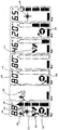
- Fig. 1
- eine Aufsicht des Gerätes gem. der Erfindung,
- Fig. 2
- die Rückansicht des Gerätes, und
- Fig. 3
- das Display des Gerätes der Fig. 1 und 2 mit allen möglichen Anzeigen,
und - Fig. 4 - 9
- das Display des Gerätes in verschiedenen Ortungsphasen.
Claims (18)
- Mittels Gurt tragbares Verschüttetensuchgerät, insbesondere für die Suche nach Lawinenverschütteten, aufweisend eine Empfangsschaltung mit einem Sender, der ein gepulstes, elektromagnetisches Feld aussendet, und mit einem Empfänger zum Empfang der Sendeimpulse, wobei die Umschaltung auf Sendebetrieb mittels eines Gurtsteckers beim Anlegen des Gurtes automatisch erfolgt, sowie mit einer Auswerteschaltung, die in Abhängigkeit von der Empfangsfeldstärke akustische und optische Anzeigemittel ansteuert sowie weiterhin mit einer mittels Schalter umschaltbaren Bereichsumschaltung für unterschiedliche Empfindlichkeitsbereiche der Empfangsfeldstärke,
dadurch gekennzeichnet, daß
die optischen Anzeigemittel der Empfangsfeldstärke aus einer Menüanzeige bestehen, die aufweist:
ein Displaymit einem einzigen, als Bargraph ausgebildeten Pfeilsymbol (12) mit Entfernungsbereichsunterteilung in Form von Balken entsprechen den Bereichen des Bereichsumschalters, die der Empfangsfeldstärke entsprechen, wobei die beim Orten empfangene maximale Feldstärke gespeichert und zusätzlich als Feldlinienlänge digital angezeigt wird und beim Verlassen der Richtung maximaler Feldstärke erlischt,mit einem Richtungsneuorientierungssymbol (21), das so lange angezeigt wird, bis die maximale Feldstärke wieder empfangen wird, undmit einem Bereichsumschaltungssymbol (22), das angezeigt wird, wenn ein Balken der Entfernungsbereichsunterteilung des Pfeilsymbols (12) überschritten wird, und eine Umschaltung des Bereichsumschalters (16) erforderlich ist. - Gerät nach Anspruch 1,
dadurch gekennzeichnet, daß
bei Verlassen der Richtung maximaler Feldstärke die Lautstärke des akustischen Signals abnimmt. - Gerät nach Anspruch 1 oder 2,
dadurch gekennzeichnet, daß
die Amplitude der maximalen Feldstärke über eine bestimmte Zeitperiode, vorzugsweise einige Minuten, gespeichert, jedoch sofort geändert wird, wenn eine größere Amplitude gemessen wird. - Gerät nach Anspruch 3,
dadurch gekennzeichnet, daß
bei Ausschalten des Gerätes oder beim Umschalten auf Sendebetrieb die vorherige Amplitude der maximalen Feldstärke gelöscht wird. - Gerät nach einem der Ansprüche 1 bis 3,
dadurch gekennzeichnet, daß
beim Zurückschalten auf einen niedrigeren Bereich des Bereichsumschalters (16) die Amplitude der maximalen Feldstärke gelöscht und gleichzeitig das Richtungsneuorientierungssymbol (21) angezeigt wird. - Gerät nach einem der Ansprüche 1 bis 5,
dadurch gekennzeichnet, daß
beim Umschalten von Sende- auf Empfangsbetrieb ein Symbol (23) für Grobsuche angezeigt wird. - Gerät nach einem der Ansprüche 1 bis 6,
dadurch gekennzeichnet, daß
beim Umschalten auf Empfangsbetrieb das Bereichsumschaltsymbol (22) angezeigt wird, falls sich der Bereichsumschalter (16) nicht in der Startposition befindet. - Gerät nach einem der Ansprüche 1 bis 7,
dadurch gekennzeichnet, daß
bei Empfangsbetrieb am Beginn der Ortung die maximale Entfernung und das Bargraph-Pfeilsymbol (12) ohne Balken leer angezeigt werden. - Gerät nach einem der Ansprüche 1 bis 8,
dadurch gekennzeichnet, daß
bei Verlassen der Richtung maximaler Feldstärke das Bargraph-Pfeilsymbol (12) auf dem bereits erreichten Entfernungsbereich gehalten wird. - Gerät nach einem der Ansprüche 1 bis 9,
dadurch gekennzeichnet, daß
bei Anzeige eines der Symbole gleichzeitig eine Alarmleuchte (14) aufleuchtet. - Gerät nach einem der Ansprüche 1 bis 10,
dadurch gekennzeichnet, daß
zusätzlich zum einen Gurtstecker (18) an einem Gurtende zum automatischen Einschalten des Sendebetriebs am anderen Gurtende ein Stecker (19) vorgesehen ist, durch den beim Lösen automatisch auf Empfangsbetrieb umgeschalten wird. - Nach Anspruch 11,
dadurch gekennzeichnet, daß
der Stecker für Empfangsbetrieb (19) mit einer am Gerät befindlichen Taste (17) zum Umschalten auf Sendebetrieb kombiniert ist. - Gerät nach Anspruch 12,
gekennzeichnet durch
einen manuell betätigbaren Auslösemechanismus (25) zum Umschalten auf Empfangsbetrieb, wenn beide Gurtendenstecker (18, 19) gelöst sind. - Gerät nach einem der Ansprüche 1 bis 13,
gekennzeichnet durch
einen manuell betätigbaren Verriegelungsmechanismus (20) zum Lösen des für die Umschaltung auf Sendebetrieb vorgesehenen Gurtsteckers. - Nach einem der Ansprüche 1 bis 14,
dadurch gekennzeichnet, daß
das Display (11) ein LC-Display ist, und daß die Symbole (12, 21, 22, 23, 24) mittels LCDs angezeigt werden. - Nach einem der Ansprüche 1 bis 15,
dadurch gekennzeichnet, daß
das Gerät auf einer Platte drehbar montiert und mittels eines Motors in Abhängigkeit von der maximalen Empfangsfeldstärke drehbar ist. - Nach Anspruch 16,
dadurch gekennzeichnet, daß
die Bereichsumschaltung automatisch in Abhängigkeit von der maximalen Empfangsfeldstärke erfolgt und angezeigt wird. - Nach einem der Ansprüche 1 bis 17,
gekennzeichnet durch
eine Schultergurtschlaufe, in der den Gurtstecker (19) aufweisenden Gurthälfte.
Applications Claiming Priority (2)
| Application Number | Priority Date | Filing Date | Title |
|---|---|---|---|
| DE19752939 | 1997-11-28 | ||
| DE19752939A DE19752939C1 (de) | 1997-11-28 | 1997-11-28 | Verschüttetensuchgerät |
Publications (2)
| Publication Number | Publication Date |
|---|---|
| EP0921412A2 true EP0921412A2 (de) | 1999-06-09 |
| EP0921412A3 EP0921412A3 (de) | 2000-01-05 |
Family
ID=7850193
Family Applications (1)
| Application Number | Title | Priority Date | Filing Date |
|---|---|---|---|
| EP98121609A Withdrawn EP0921412A3 (de) | 1997-11-28 | 1998-11-12 | Verschüttetensuchgerät |
Country Status (3)
| Country | Link |
|---|---|
| US (1) | US6246863B1 (de) |
| EP (1) | EP0921412A3 (de) |
| DE (1) | DE19752939C1 (de) |
Families Citing this family (27)
| Publication number | Priority date | Publication date | Assignee | Title |
|---|---|---|---|---|
| DE19961112C2 (de) * | 1999-12-17 | 2001-12-13 | Christian Hano | Verschüttetensuchgerät |
| TW428439U (en) * | 2000-03-15 | 2001-04-01 | Taiwan Ind Fastener Corp | Press buckle |
| DE10030719C2 (de) * | 2000-06-16 | 2002-09-12 | Erika Grabowski | Neues Lawinen-Verschütteten-Suchsystem |
| US7480522B2 (en) * | 2002-12-31 | 2009-01-20 | Nokia Corporation | Rocker user interface for handheld devices, and method for implementing same |
| AT413449B (de) * | 2003-01-15 | 2006-03-15 | Seidel Elektronik Gmbh Nfg Kg | Suchgerät, insbesonders zur ortung verschütteter personen in lawinen, sowie verfahren zum betreiben eines suchgerätes |
| CA2443751A1 (en) * | 2003-10-22 | 2005-04-22 | Douglas Kashuba | Avalanche transceiver |
| DE102004027314B4 (de) * | 2004-03-17 | 2006-03-23 | Gerald Kampel | Lawinen-Verschütteten-Suchgerät und Verfahren zur Ortung eines Senders |
| US7346336B2 (en) * | 2004-08-10 | 2008-03-18 | Gerald Kampel | Personal activity sensor and locator device |
| JP4528587B2 (ja) * | 2004-09-21 | 2010-08-18 | 株式会社東海理化電機製作所 | 携帯機 |
| DE102005025948B4 (de) * | 2005-06-06 | 2008-11-06 | Ethan Ho | Führungssystem für die Evakuierung im Notfall |
| EP1746433B1 (de) * | 2005-07-18 | 2007-08-29 | Gerald Kampel | Verfahren und Vorrichtung zum Auffinden eines Verschütteten |
| EP1785169B1 (de) | 2005-11-14 | 2013-04-17 | Mammut Sports Group AG | Such- und Sendegerät |
| US7632239B2 (en) * | 2005-11-16 | 2009-12-15 | Bioness Neuromodulation Ltd. | Sensor device for gait enhancement |
| US8972017B2 (en) | 2005-11-16 | 2015-03-03 | Bioness Neuromodulation Ltd. | Gait modulation system and method |
| US7899556B2 (en) | 2005-11-16 | 2011-03-01 | Bioness Neuromodulation Ltd. | Orthosis for a gait modulation system |
| US8209022B2 (en) * | 2005-11-16 | 2012-06-26 | Bioness Neuromodulation Ltd. | Gait modulation system and method |
| EP2012669B1 (de) | 2006-05-01 | 2013-03-13 | Bioness Neuromodulation Ltd | Verbesserte funktionale elektrische stimulationssysteme |
| US7839290B2 (en) * | 2006-11-01 | 2010-11-23 | David Welford Chidakel | Sonic building rescue beacon |
| EP1941933A1 (de) | 2007-01-03 | 2008-07-09 | Gerald Kampel | Modulare Einheit für eine Lawinensonde und Lawinensonde |
| CH700278B1 (de) * | 2007-08-09 | 2010-06-15 | Ampass Explorer Corp | Gehäuse für ein Suchantennen-Polarisationsinstrument. |
| WO2010098869A2 (en) * | 2009-02-27 | 2010-09-02 | Paul Stuart Auerbach | Avalanche rescue device |
| US20110193702A1 (en) * | 2010-02-05 | 2011-08-11 | Brooks William Mathews | Wireless apparatuses, systems, and methods for locating items |
| US9867985B2 (en) | 2014-03-24 | 2018-01-16 | Bioness Inc. | Systems and apparatus for gait modulation and methods of use |
| WO2017123608A1 (en) | 2016-01-11 | 2017-07-20 | Bioness Inc. | Systems and apparatus for gait modulation and methods of use |
| USD1015321S1 (en) | 2021-01-19 | 2024-02-20 | Black Diamond Equipment, Ltd. | Beacon cradle |
| CA3215069A1 (en) * | 2021-05-19 | 2022-11-24 | David Vanhorn | Avalanche transceiver |
| US12668372B2 (en) * | 2023-10-17 | 2026-06-30 | The Boeing Company | Systems, methods, and apparatus for monitoring life vests on aircraft |
Family Cites Families (7)
| Publication number | Priority date | Publication date | Assignee | Title |
|---|---|---|---|---|
| US4300129A (en) * | 1978-09-06 | 1981-11-10 | Cataldo Thomas R | Silent wearable signalling device with tactile means to prevent false triggering |
| DE3046895C2 (de) * | 1980-12-12 | 1982-09-23 | Gerald 8021 Taufkirchen Kampel | Verschüttetensuchgerät, insbesondere für die Verwendung bei der Suche nach Lawinenverschütteten |
| DE3531726A1 (de) * | 1985-09-05 | 1987-03-05 | Gerald Kampel | Verschuettetensuchgeraet |
| DE3817272A1 (de) * | 1988-05-20 | 1989-11-30 | Armin Dr Tiefengraber | Skifahrer-sicherheitspass-system liftkarte, skipass o. ae. zusammen mit inikator (sender + empfaenger + energiequelle o. ae.) als einheit |
| DE19510875C1 (de) * | 1995-03-24 | 1996-09-05 | Silvretta Sherpas Sportartikel | Tragbares Ortungsgerät |
| FR2742874B1 (fr) * | 1995-12-22 | 1998-03-13 | Onera (Off Nat Aerospatiale) | Procede et systeme pour la detection et localisation d'un individu, par exemple enseveli sous un depot d'avalanche |
| GB9601528D0 (en) * | 1996-01-25 | 1996-03-27 | Chignell Richard J | Underground pipe locating system |
-
1997
- 1997-11-28 DE DE19752939A patent/DE19752939C1/de not_active Expired - Fee Related
-
1998
- 1998-11-12 EP EP98121609A patent/EP0921412A3/de not_active Withdrawn
- 1998-11-23 US US09/198,001 patent/US6246863B1/en not_active Expired - Lifetime
Also Published As
| Publication number | Publication date |
|---|---|
| US6246863B1 (en) | 2001-06-12 |
| EP0921412A3 (de) | 2000-01-05 |
| DE19752939C1 (de) | 1999-08-26 |
Similar Documents
| Publication | Publication Date | Title |
|---|---|---|
| DE19752939C1 (de) | Verschüttetensuchgerät | |
| DE19510875C1 (de) | Tragbares Ortungsgerät | |
| DE10003338A1 (de) | System zum Orten implantierbarer medizinischer Geräte | |
| AT413449B (de) | Suchgerät, insbesonders zur ortung verschütteter personen in lawinen, sowie verfahren zum betreiben eines suchgerätes | |
| DE69915212T2 (de) | Kapazitive Wegmesseinrichtung | |
| DE2542451A1 (de) | Vorrichtung zum bestimmen der lage eines objektes entlang einer festen strecke, insbesondere der lage einer gewinnungsmaschine im untertaegigen bergbau | |
| DE2408333A1 (de) | Einrichtung zur abstandsmessung | |
| DE4103234A1 (de) | Verfahren und leitungssucher zum beruehrungslosen suchen und identifizieren von elektrischen leitungen | |
| EP1019754B1 (de) | Verschüttetensuchgerät | |
| AT391562B (de) | Verschuettetensuchgeraet | |
| DE19516789A1 (de) | Vorrichtung zur Überwachung des Füllstandes eines Vorratsbehälters | |
| DE19958543C1 (de) | Verfahren und Vorrichtung zum Nivellieren von Gelände | |
| DE2953405C2 (de) | ||
| DE2919024A1 (de) | Vorrichtung zur bestimmung der einfuehrungsrichtung und -tiefe von injektionsnadeln, sonden u.dgl. in einen koerper | |
| EP0095040A1 (de) | Geschwindigkeitsmesser für strömende Medien | |
| DE19611757C1 (de) | Verfahren und Meßanordnung zur Ortung von im Erdreich befindlichen Objekten | |
| DE19652977C1 (de) | Ortungseinrichtung für im Erdbereich befindliche Objekte | |
| EP1700623B1 (de) | Sonde, insbesondere zur Ortung verschütteter Personen, sowie Verschütteten-Suchsystem | |
| DE68904439T2 (de) | Einrichtung zur anzeige von azimut- und neigungsrichtungen. | |
| EP0780705A2 (de) | Elektromagnetisches Suchverfahren und Sondenanordnung zur Ortung von unter der Oberfläche liegenden Objekten | |
| DE1623110A1 (de) | Vorrichtung fuer die elektrische Ortung von Gegenstaenden aus Metall | |
| DE720893C (de) | Einrichtung zur Vermeidung von bei drahtlosen Navigationsmessungen durch Schraeglage des die Messapparatur tragenden Fahrzeuges bedingten Messfehlern | |
| DE69710705T2 (de) | Uhr verbunden mit einem Kompass und einem Sucher | |
| AT6120U2 (de) | Suchgerät, insbesonders zur ortung verschütteter personen in lawinen, sowie verfahren zum betreiben eines suchgerätes | |
| DE2165205A1 (de) | Steuervorrichtung für einen Flugkörper |
Legal Events
| Date | Code | Title | Description |
|---|---|---|---|
| PUAI | Public reference made under article 153(3) epc to a published international application that has entered the european phase |
Free format text: ORIGINAL CODE: 0009012 |
|
| AK | Designated contracting states |
Kind code of ref document: A2 Designated state(s): AT CH DE FR IT LI |
|
| AX | Request for extension of the european patent |
Free format text: AL;LT;LV;MK;RO;SI |
|
| PUAL | Search report despatched |
Free format text: ORIGINAL CODE: 0009013 |
|
| AK | Designated contracting states |
Kind code of ref document: A3 Designated state(s): AT BE CH CY DE DK ES FI FR GB GR IE IT LI LU MC NL PT SE |
|
| AX | Request for extension of the european patent |
Free format text: AL;LT;LV;MK;RO;SI |
|
| RIC1 | Information provided on ipc code assigned before grant |
Free format text: 7G 01S 13/04 A, 7G 01S 13/88 B, 7G 01S 7/04 B, 7A 63B 29/02 B, 7G 01S 3/04 B |
|
| 17P | Request for examination filed |
Effective date: 20000316 |
|
| AKX | Designation fees paid |
Free format text: AT CH DE FR IT LI |
|
| GRAG | Despatch of communication of intention to grant |
Free format text: ORIGINAL CODE: EPIDOS AGRA |
|
| 17Q | First examination report despatched |
Effective date: 20020321 |
|
| GRAG | Despatch of communication of intention to grant |
Free format text: ORIGINAL CODE: EPIDOS AGRA |
|
| GRAH | Despatch of communication of intention to grant a patent |
Free format text: ORIGINAL CODE: EPIDOS IGRA |
|
| STAA | Information on the status of an ep patent application or granted ep patent |
Free format text: STATUS: THE APPLICATION IS DEEMED TO BE WITHDRAWN |
|
| 18D | Application deemed to be withdrawn |
Effective date: 20021112 |