EP0921507B1 - Verfahren zum Ändern des Verhaltens eines Stellglieds einer Stellgliedgruppe - Google Patents
Verfahren zum Ändern des Verhaltens eines Stellglieds einer Stellgliedgruppe Download PDFInfo
- Publication number
- EP0921507B1 EP0921507B1 EP98122170A EP98122170A EP0921507B1 EP 0921507 B1 EP0921507 B1 EP 0921507B1 EP 98122170 A EP98122170 A EP 98122170A EP 98122170 A EP98122170 A EP 98122170A EP 0921507 B1 EP0921507 B1 EP 0921507B1
- Authority
- EP
- European Patent Office
- Prior art keywords
- actuators
- transmitter
- actuator
- remote control
- particular operation
- Prior art date
- Legal status (The legal status is an assumption and is not a legal conclusion. Google has not performed a legal analysis and makes no representation as to the accuracy of the status listed.)
- Expired - Lifetime
Links
- 238000000034 method Methods 0.000 title claims description 24
- 230000005540 biological transmission Effects 0.000 claims description 9
- 239000013256 coordination polymer Substances 0.000 claims 1
- 238000009434 installation Methods 0.000 abstract description 17
- 230000005236 sound signal Effects 0.000 abstract description 4
- 230000003213 activating effect Effects 0.000 abstract 3
- 239000012190 activator Substances 0.000 abstract 1
- 230000005672 electromagnetic field Effects 0.000 abstract 1
- 230000015654 memory Effects 0.000 description 5
- 230000035945 sensitivity Effects 0.000 description 5
- 238000010586 diagram Methods 0.000 description 2
- IUVCFHHAEHNCFT-INIZCTEOSA-N 2-[(1s)-1-[4-amino-3-(3-fluoro-4-propan-2-yloxyphenyl)pyrazolo[3,4-d]pyrimidin-1-yl]ethyl]-6-fluoro-3-(3-fluorophenyl)chromen-4-one Chemical compound C1=C(F)C(OC(C)C)=CC=C1C(C1=C(N)N=CN=C11)=NN1[C@@H](C)C1=C(C=2C=C(F)C=CC=2)C(=O)C2=CC(F)=CC=C2O1 IUVCFHHAEHNCFT-INIZCTEOSA-N 0.000 description 1
- 230000004913 activation Effects 0.000 description 1
- 230000003313 weakening effect Effects 0.000 description 1
Images

Classifications
-
- G—PHYSICS
- G08—SIGNALLING
- G08C—TRANSMISSION SYSTEMS FOR MEASURED VALUES, CONTROL OR SIMILAR SIGNALS
- G08C19/00—Electric signal transmission systems
- G08C19/16—Electric signal transmission systems in which transmission is by pulses
- G08C19/28—Electric signal transmission systems in which transmission is by pulses using pulse code
Definitions
- the invention relates to a method of individual configuration of the actuators of a group of actuators arranged at a distance from each other, each equipped with a receiver and each controllable by at least one remote control transmitter to associate at least a remote control transmitter with at least one actuator.
- the invention relates more particularly to an installation in which the actuators can not be individually the object of a particular maneuver, such as actuation of a pushbutton accessible at the actuator or power supply cutoff individualized actuator.
- a particular maneuver such as actuation of a pushbutton accessible at the actuator or power supply cutoff individualized actuator.
- This is for example the case of a building equipped with motorized shutters housed in boxes each equipped with a receiver controllable by means of a remote control.
- a remote control Such an installation is described in the patent FR 2,743,390 . If, in such an installation, it is desired to associate certain actuators with certain remote control boxes, it is either necessary to intervene in the box, or it is necessary to carry out this association in the factory before installation. Access to the installed caisson is generally difficult, so that a configuration of the actuators must usually be abandoned once the installation is complete.
- the present invention aims, by a simple method, to allow the individual configuration of the elements of an actuator group, that is to say the individual association of each of the actuators with one or more remote control transmitters, without manual intervention at the actuator.
- the method according to the invention is characterized in that, by a particular maneuver, all the actuators are first able to receive the only signals emitted in a reduced transmission field, when a transmitter of an actuator is approached so that it receives the signals emitted by said transmitter, which is sent, by means of the close transmitter, a configuration signal containing a training frame and identification of the transmitter, that the The actuator restores the normal transmission field between itself and the close transmitter at the end of the configuration procedure and the process is repeated with each receiver.
- Such a process differs essentially from the process described in the document GB-A 2,287,337 intended to associate a receiver-transmitter of a particular vehicle with a particular garage door. In this case, it is only necessary to isolate the receiver of this receiver-transmitter from the other control boxes to distance associated with each door actuator, while learning the code transmitted by this particular remote control.
- the restoration of the initial field of reception is not intended to allow the control of several actuators, that is to say of several garage doors by a single remote control, but only to allow the control of the actuator by the car at a sufficiently large distance.
- the reduction of the transmission field can be done either by weakening the reception by reducing the gain of the receiver amplifiers or by reducing the transmit power of the transmitters.
- the simplest way to send a signal to all the actuators is to use the power supply wires of the actuators, in particular to use the power on or off of the actuators.
- the particular maneuver could thus be for example the first power up or a coded sequence of cuts of the power supply.
- the general switch actuators of the building In the case of roller shutters equipping a building, one could use for this purpose the general switch actuators of the building.
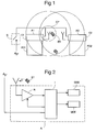
- the installation represented at figure 1 comprises a group of actuators of which only two actuators A1, A2 have been shown. These actuators are housed in a box C1, C2 and animate occultation products PO1, PO2, such as shutters.
- the actuators A1, A2 are powered by the sector via a common switch S.
- the actuators are remotely controllable by means of at least one remote control transmitter ET.
- the actuator ( figure 2 ) comprises a variable gain receiver R, an intelligence I, a signal generator GSS and a MOT motor.
- the intelligence I comprises, in a conventional manner, a calculator, memories and interfaces. The intelligence I is therefore able to record instructions and information obtained by learning.
- the return to the initial state can be done either automatically or by an action on the remote control unit. As indicated in the second procedure, the return to the initial state can be done after the lapse of a certain time. If the actuator is equipped with a sound signal generator GSS, the intelligence of the actuator can control the emission of a sound signal to signify that the procedure is complete.
- the reduction of the transmission field between the emitters and the actuators can also be achieved by reducing the power of the remote control transmitters.
- This second embodiment is illustrated by the Figures 3 and 4 . To the figure 3 , we find the same elements as at the figure 1 . When the remote control transmitters ET are at a certain distance, normal, actuators A1, A2 and the power of these transmitters is reduced so that an actuator located outside the field P does not pick up any signal, the remote control transmitters are without influence on actuators. It is then necessary to bring an AND remote control of an actuator, for example A1, so that this actuator captures the signals emitted by the remote control transmitter.
- Each remote control transmitter ET comprises an intelligence I 'equipped with a receiver and a transmitter E comprising a variable gain amplifier.
- Each actuator A comprises an intelligence I comprising a fixed gain transmitter / receiver and, as in the first case, a MOT motor and a GSS sound signal generator.
- the actuators A By a particular maneuver, for example the first activation of the actuators by means of the disconnector S, the actuators A emit a signal received by the remote control transmitters and interpreted by them as an order to reduce the power, that is, ie the range, of their transmitter.
- the remote control transmitter ET to be associated with an actuator A is then approached from this actuator, for example from the actuator A1 as shown in FIG. figure 3 , and the user transmits, by means of this remote control, a learning and identification frame which is only received by the actuator A1.
- This actuator receives the frame and records the code of the transmitter.
- This transmitter once recognized by the actuator A1 receives an order to transmit again at full power.
- the association is then completed for this particular remote control, which, in addition, is no longer capable of transmitting training frames, so that it does not risk being mistakenly learned by another actuator.
- a remote control can therefore be associated with only one actuator, while in the first embodiment, a remote control can be associated with any number of actuators.
Landscapes
- Physics & Mathematics (AREA)
- General Physics & Mathematics (AREA)
- Selective Calling Equipment (AREA)
- Vehicle Body Suspensions (AREA)
- Operation Control Of Excavators (AREA)
- Control Of Position Or Direction (AREA)
- Blinds (AREA)
Claims (6)
- Verfahren zur individuellen Konfiguration der Stellglieder einer Gruppe von Stellgliedern (A1, A2), die im Abstand voneinander angeordnet sind und jeweils einen Empfänger aufweisen und über mindestens einen Sender einer Fernbedienung ET steuerbar sind, um mindestens einen Fernsteuerungssender mindestens einem Stellglied zuzuordnen,
dadurch gekennzeichnet, dass zunächst sämtliche Stellglieder mittels einer besonderen Betätigung (S) so gesteuert werden, dass sie ausschliesslich Signale empfangen, welche in einem eingeschränkten Übertragungsgebiet (CP; P) ausgestrahlt werden;
dass ein Sender einem Stellglied genähert wird, damit dieses die vom genannten Sender ausgestrahlten Signale empfängt;
dass mittels des angenäherten Senders ein Konfigurationssignal ausgesandt wird, welches ein Lern- und Identifikationsraster des Senders enthält;
dass das Stellglied am Ende der Konfiguration das normale Übertragungsgebiet zwischen dem Stellglied und dem angenäherten Sender wiederherstellt; und
dass das Verfahren mit jedem Stellglied und jeder Fernbedienung wiederholt wird. - Verfahren nach Anspruch 1, dadurch gekennzeichnet, dass die besondere Betätigung eine Verminderung des Verstärkungsfaktors der Verstärker der Stellglied-Empfänger bewirkt.
- Verfahren nach Anspruch 1, dadurch gekennzeichnet, dass die besondere Betätigung eine Verminderung der Sendeleistung sämtlicher Fernsteuerungssender durch ein Signal bewirkt, welches von allen Stellgliedern ausgesandt wird.
- Verfahren nach Anspruch 3, dadurch gekennzeichnet, dass die Wiederherstellung der normalen Sendeleistung der Fernsteuerungssender bewirkt, dass diese Fernsteuerungssender daran gehindert werden, ein Konfigurationssignal erneut auszusenden.
- Verfahren nach einem der Ansprüche 1 bis 4, dadurch gekennzeichnet, dass die besondere Betätigung darin besteht, dass die Stellglieder über einen allgemeinen Trennschalter (S) erstmalig unter Spannung gesetzt werden.
- Verfahren nach einem der Ansprüche 1 bis 4, dadurch gekennzeichnet, dass die besondere Betätigung darin besteht, dass die Stromversorgung der Stellglieder über einen allgemeinen Trennschalter (S) mehrmals abgeschaltet wird.
Applications Claiming Priority (2)
| Application Number | Priority Date | Filing Date | Title |
|---|---|---|---|
| FR9715470A FR2772171B1 (fr) | 1997-12-08 | 1997-12-08 | Procede de configuration des actionneurs d'un groupe d'actionneurs |
| FR9715470 | 1997-12-08 |
Publications (2)
| Publication Number | Publication Date |
|---|---|
| EP0921507A1 EP0921507A1 (de) | 1999-06-09 |
| EP0921507B1 true EP0921507B1 (de) | 2008-03-05 |
Family
ID=9514288
Family Applications (1)
| Application Number | Title | Priority Date | Filing Date |
|---|---|---|---|
| EP98122170A Expired - Lifetime EP0921507B1 (de) | 1997-12-08 | 1998-11-26 | Verfahren zum Ändern des Verhaltens eines Stellglieds einer Stellgliedgruppe |
Country Status (5)
| Country | Link |
|---|---|
| EP (1) | EP0921507B1 (de) |
| AT (1) | ATE388462T1 (de) |
| DE (1) | DE69839207T2 (de) |
| ES (1) | ES2133257T1 (de) |
| FR (1) | FR2772171B1 (de) |
Families Citing this family (8)
| Publication number | Priority date | Publication date | Assignee | Title |
|---|---|---|---|---|
| FR2826521B1 (fr) * | 2001-06-26 | 2003-09-26 | Somfy | Dispositif de commande radiotelecommandee |
| FR2827414B1 (fr) | 2001-07-13 | 2003-12-05 | Somfy | Procede d'appariement d'emetteur et de recepteur |
| FR2838523B1 (fr) | 2002-04-16 | 2006-06-23 | Siminor Technologies Castres S | Procede d'interpretation d'un ordre radio-electronique en fonction de sa zone d'emission |
| FR2841016B1 (fr) * | 2002-06-18 | 2004-09-10 | Somfy | Procede de configuration d'un reseau d'elements de commande d'equipements |
| FR2843463B1 (fr) * | 2002-08-06 | 2005-03-11 | Somfy | Procede d'appariement entre un emetteur d'ordres et un recepteur d'ordres pilotant un equipement comportant un element mobile |
| FR2847060B1 (fr) | 2002-11-12 | 2005-02-11 | Somfy Sas | Procede de securisation du mode d'enregistrement d'un dispositif pilotant un element assurant la securite et/ou le confort d'un batiment |
| FR2869481B1 (fr) * | 2004-04-27 | 2006-06-23 | Somfy Soc Par Actions Simplifi | Actionneur pour la manoeuvre d'un volet roulant |
| FR2999006B1 (fr) | 2012-12-05 | 2016-01-01 | Somfy Sas | Procede d’appairage de deux appareillages communicants d’une installation domotique et installation associee |
Family Cites Families (3)
| Publication number | Priority date | Publication date | Assignee | Title |
|---|---|---|---|---|
| US4529980A (en) * | 1982-09-23 | 1985-07-16 | Chamberlain Manufacturing Corporation | Transmitter and receiver for controlling the coding in a transmitter and receiver |
| US5627529A (en) * | 1994-03-11 | 1997-05-06 | Prince Corporation | Vehicle control system with trainable transceiver |
| EP0477409B1 (de) * | 1990-09-27 | 1995-11-22 | Siemens Aktiengesellschaft | Fernsteuersystem mit freier Gruppenbildung |
-
1997
- 1997-12-08 FR FR9715470A patent/FR2772171B1/fr not_active Expired - Fee Related
-
1998
- 1998-11-26 AT AT98122170T patent/ATE388462T1/de not_active IP Right Cessation
- 1998-11-26 DE DE69839207T patent/DE69839207T2/de not_active Expired - Fee Related
- 1998-11-26 ES ES98122170T patent/ES2133257T1/es active Pending
- 1998-11-26 EP EP98122170A patent/EP0921507B1/de not_active Expired - Lifetime
Also Published As
| Publication number | Publication date |
|---|---|
| DE69839207T2 (de) | 2009-03-19 |
| EP0921507A1 (de) | 1999-06-09 |
| ATE388462T1 (de) | 2008-03-15 |
| DE69839207D1 (de) | 2008-04-17 |
| FR2772171A1 (fr) | 1999-06-11 |
| ES2133257T1 (es) | 1999-09-16 |
| FR2772171B1 (fr) | 2000-06-30 |
Similar Documents
| Publication | Publication Date | Title |
|---|---|---|
| EP2259242B1 (de) | Verfahren zur Kommunikation zwischen einer mobilen Fernbedienung und Heimeinrichtungen über ein Relais | |
| EP2083408B1 (de) | Informationsübertragungsverfahren über Infrarotstrahlen zwischen einem Sender und einem Empfänger in einem Heimnetz | |
| EP0426577B1 (de) | Verfahren und Vorrichtung zum Verstellen einer Verdunkelungsanordnung in justierbaren Positionen und Installation zur Durchführung der Anmeldung | |
| EP0921507A1 (de) | Verfahren zum Ändern des Verhaltens eines Stellglieds einer Stellgliedgruppe | |
| EP0867848B1 (de) | Steuerungsvorrichtung für einen ferngesteuerten Aktuator | |
| FR2684785A1 (fr) | Dispositif de generation de signalisation sonore pour pietons. | |
| EP2374975B1 (de) | Konfigurationsverfahren einer motorisierungsvorrichtung einer hausanlage, die mit einem fensterladen ausgestattet ist, und entsprechende motorisierungsvorrichtung einer hausanlage, die mit einem fensterladen ausgestattet ist | |
| EP2551434A2 (de) | System und Verfahren zur Öffnung und Schließung von Klappflügeln, mit einem solchen System ausgestattete Anlage und Heimanlage, die mindestens zwei Anlagen umfasst | |
| EP0718729B1 (de) | Steuergerät für aktive elektrische Lasten, wie Rolläden, Beleuchtung oder dergleichen | |
| EP1446548A1 (de) | Verfahren zum abstimmen auf den gegebenen richtungsbefehl eines elektromotors in einer verschlussanlage oder dergleichen wie zum beispiel einem rollladen | |
| FR2919097A1 (fr) | Procede de fonctionnement d'un emetteur d'ordres dans une installation domotique et emetteur d'ordres pour sa mise en oeuvre | |
| EP1527377B1 (de) | Anpassungsverfahren zwischen einem befehlssender und einem befehlsempfänger | |
| EP1172516B1 (de) | Steuervorrichtung für Rolladen | |
| EP0997605B1 (de) | Verfahren und Vorrichtung zur Steuerung einer oder mehrerer Geräte, insbesondere einer in zwei Richtungen drehbaren Rolladenwalze | |
| EP3312689B1 (de) | Verfahren zur betriebssteuerung einer domotik-anlage, und entsprechende domotik-anlage | |
| EP1469364B1 (de) | Verfahren zum Bilden einer Gruppe von Gliedern in einem Gebäudenetzwerk | |
| FR2850779A1 (fr) | Procede de fermeture des acces a un batiment | |
| EP1253568B1 (de) | Verfahren und Vorrichtung zur Konfigurierung von Fernbedienungsgeräten | |
| JP3289022B2 (ja) | リモートコントロール受信装置 | |
| EP1699030B1 (de) | Verfahren zur drahtlosen Fernsteuerung | |
| EP3023960A2 (de) | Motorisierte antriebsvorrichtung für eine heimanlage zum schliessen | |
| FR2855298A1 (fr) | Installation d'alarme sans fil a relais et procede de relayage. | |
| EP4112859A1 (de) | Motorisierte antriebsvorrichtung für eine hausschliessanlage | |
| FR2877474A1 (fr) | Procede d'enregistrement d'une seconde telecommande dans un recepteur associe a un actionneur | |
| FR2797695A1 (fr) | Dispositif de programmation horaire de commande de fermeture et/ou d'ouverture d'un systeme d'occultation ou similaire |
Legal Events
| Date | Code | Title | Description |
|---|---|---|---|
| PUAI | Public reference made under article 153(3) epc to a published international application that has entered the european phase |
Free format text: ORIGINAL CODE: 0009012 |
|
| AK | Designated contracting states |
Kind code of ref document: A1 Designated state(s): AT BE CH DE ES GB IT LI NL SE |
|
| AX | Request for extension of the european patent |
Free format text: AL;LT;LV;MK;RO;SI |
|
| REG | Reference to a national code |
Ref country code: ES Ref legal event code: BA2A Ref document number: 2133257 Country of ref document: ES Kind code of ref document: T1 |
|
| 17P | Request for examination filed |
Effective date: 19991023 |
|
| AKX | Designation fees paid |
Free format text: AT BE CH DE ES GB IT LI NL SE |
|
| RAP1 | Party data changed (applicant data changed or rights of an application transferred) |
Owner name: SOMFY |
|
| RAP1 | Party data changed (applicant data changed or rights of an application transferred) |
Owner name: SOMFY SAS |
|
| GRAP | Despatch of communication of intention to grant a patent |
Free format text: ORIGINAL CODE: EPIDOSNIGR1 |
|
| GRAS | Grant fee paid |
Free format text: ORIGINAL CODE: EPIDOSNIGR3 |
|
| GRAA | (expected) grant |
Free format text: ORIGINAL CODE: 0009210 |
|
| AK | Designated contracting states |
Kind code of ref document: B1 Designated state(s): AT BE CH DE ES GB IT LI NL SE |
|
| REG | Reference to a national code |
Ref country code: GB Ref legal event code: FG4D Free format text: NOT ENGLISH |
|
| REG | Reference to a national code |
Ref country code: CH Ref legal event code: EP |
|
| REF | Corresponds to: |
Ref document number: 69839207 Country of ref document: DE Date of ref document: 20080417 Kind code of ref document: P |
|
| PG25 | Lapsed in a contracting state [announced via postgrant information from national office to epo] |
Ref country code: ES Free format text: LAPSE BECAUSE OF FAILURE TO SUBMIT A TRANSLATION OF THE DESCRIPTION OR TO PAY THE FEE WITHIN THE PRESCRIBED TIME-LIMIT Effective date: 20080616 |
|
| PG25 | Lapsed in a contracting state [announced via postgrant information from national office to epo] |
Ref country code: AT Free format text: LAPSE BECAUSE OF FAILURE TO SUBMIT A TRANSLATION OF THE DESCRIPTION OR TO PAY THE FEE WITHIN THE PRESCRIBED TIME-LIMIT Effective date: 20080305 |
|
| NLV1 | Nl: lapsed or annulled due to failure to fulfill the requirements of art. 29p and 29m of the patents act | ||
| PG25 | Lapsed in a contracting state [announced via postgrant information from national office to epo] |
Ref country code: SE Free format text: LAPSE BECAUSE OF FAILURE TO SUBMIT A TRANSLATION OF THE DESCRIPTION OR TO PAY THE FEE WITHIN THE PRESCRIBED TIME-LIMIT Effective date: 20080605 Ref country code: NL Free format text: LAPSE BECAUSE OF FAILURE TO SUBMIT A TRANSLATION OF THE DESCRIPTION OR TO PAY THE FEE WITHIN THE PRESCRIBED TIME-LIMIT Effective date: 20080305 |
|
| PLBE | No opposition filed within time limit |
Free format text: ORIGINAL CODE: 0009261 |
|
| STAA | Information on the status of an ep patent application or granted ep patent |
Free format text: STATUS: NO OPPOSITION FILED WITHIN TIME LIMIT |
|
| 26N | No opposition filed |
Effective date: 20081208 |
|
| BERE | Be: lapsed |
Owner name: SOMFY SAS Effective date: 20081130 |
|
| REG | Reference to a national code |
Ref country code: CH Ref legal event code: PL |
|
| GBPC | Gb: european patent ceased through non-payment of renewal fee |
Effective date: 20081126 |
|
| PG25 | Lapsed in a contracting state [announced via postgrant information from national office to epo] |
Ref country code: IT Free format text: LAPSE BECAUSE OF FAILURE TO SUBMIT A TRANSLATION OF THE DESCRIPTION OR TO PAY THE FEE WITHIN THE PRESCRIBED TIME-LIMIT Effective date: 20080305 |
|
| PG25 | Lapsed in a contracting state [announced via postgrant information from national office to epo] |
Ref country code: BE Free format text: LAPSE BECAUSE OF NON-PAYMENT OF DUE FEES Effective date: 20081130 |
|
| PG25 | Lapsed in a contracting state [announced via postgrant information from national office to epo] |
Ref country code: LI Free format text: LAPSE BECAUSE OF NON-PAYMENT OF DUE FEES Effective date: 20081130 Ref country code: DE Free format text: LAPSE BECAUSE OF NON-PAYMENT OF DUE FEES Effective date: 20090603 Ref country code: CH Free format text: LAPSE BECAUSE OF NON-PAYMENT OF DUE FEES Effective date: 20081130 |
|
| PG25 | Lapsed in a contracting state [announced via postgrant information from national office to epo] |
Ref country code: GB Free format text: LAPSE BECAUSE OF NON-PAYMENT OF DUE FEES Effective date: 20081126 |