EP0921546A1 - Dispositif de traverse, notamment pour boítier d'équipement électrique - Google Patents
Dispositif de traverse, notamment pour boítier d'équipement électrique Download PDFInfo
- Publication number
- EP0921546A1 EP0921546A1 EP98410129A EP98410129A EP0921546A1 EP 0921546 A1 EP0921546 A1 EP 0921546A1 EP 98410129 A EP98410129 A EP 98410129A EP 98410129 A EP98410129 A EP 98410129A EP 0921546 A1 EP0921546 A1 EP 0921546A1
- Authority
- EP
- European Patent Office
- Prior art keywords
- end piece
- intended
- base
- housing
- seal
- Prior art date
- Legal status (The legal status is an assumption and is not a legal conclusion. Google has not performed a legal analysis and makes no representation as to the accuracy of the status listed.)
- Granted
Links
- 230000002787 reinforcement Effects 0.000 claims description 2
- 230000007246 mechanism Effects 0.000 abstract description 2
- 238000007789 sealing Methods 0.000 abstract 1
- 210000002445 nipple Anatomy 0.000 description 5
- 239000000463 material Substances 0.000 description 3
- 229920001169 thermoplastic Polymers 0.000 description 2
- 239000004416 thermosoftening plastic Substances 0.000 description 2
- 230000004075 alteration Effects 0.000 description 1
- 235000021183 entrée Nutrition 0.000 description 1
- 210000004907 gland Anatomy 0.000 description 1
- 238000009434 installation Methods 0.000 description 1
- 239000012528 membrane Substances 0.000 description 1
- 210000003813 thumb Anatomy 0.000 description 1
Images

Classifications
-
- H—ELECTRICITY
- H02—GENERATION; CONVERSION OR DISTRIBUTION OF ELECTRIC POWER
- H02G—INSTALLATION OF ELECTRIC CABLES OR LINES, OR OF COMBINED OPTICAL AND ELECTRIC CABLES OR LINES
- H02G3/00—Installations of electric cables or lines or protective tubing therefor in or on buildings, equivalent structures or vehicles
- H02G3/02—Details
- H02G3/08—Distribution boxes; Connection or junction boxes
- H02G3/10—Distribution boxes; Connection or junction boxes for surface mounting on a wall
-
- H—ELECTRICITY
- H01—ELECTRIC ELEMENTS
- H01H—ELECTRIC SWITCHES; RELAYS; SELECTORS; EMERGENCY PROTECTIVE DEVICES
- H01H9/00—Details of switching devices, not covered by groups H01H1/00 - H01H7/00
- H01H9/02—Bases, casings, or covers
- H01H9/04—Dustproof, splashproof, drip-proof, waterproof, or flameproof casings
-
- H—ELECTRICITY
- H02—GENERATION; CONVERSION OR DISTRIBUTION OF ELECTRIC POWER
- H02G—INSTALLATION OF ELECTRIC CABLES OR LINES, OR OF COMBINED OPTICAL AND ELECTRIC CABLES OR LINES
- H02G3/00—Installations of electric cables or lines or protective tubing therefor in or on buildings, equivalent structures or vehicles
- H02G3/02—Details
- H02G3/08—Distribution boxes; Connection or junction boxes
- H02G3/088—Dustproof, splashproof, drip-proof, waterproof, or flameproof casings or inlets
Definitions
- the present invention relates to a crossing device in particular for a housing or a envelope of electrical equipment, said housing comprising a base and a cover, said base comprising a bottom wall by which said housing is intended to be fixed on a bearing surface and side walls, said device comprising a closure end piece capable of being detachably and tightly fixed in an opening of conjugate shape formed in one of the side walls of the housing by means of fixing provided in partly on the housing and partly on the end piece, so as to allow the sealed passage of a connection element, in particular a conduit or a cable.
- This device consists of a tip comprising a first ring-shaped element made of a rigid material and a second crossing element made of a flexible material, fixed inside the first element by completely closing the orifice delimited by the ring.
- This first element in rigid material comprises latching means intended to cooperate with the edges internal of the housing opening, to ensure the attachment of the nozzle in said opening.
- the electrical equipment boxes are intended to be fixed on a bearing surface like a wall by means of fixing screws passing through their bottom wall.
- Enclosed boxes of inputs as described above have the disadvantage of being deformed during the fixing operation. This results in an alteration of the tightness of the assembly.
- the present invention solves these problems and proposes a crossing device for a housing. of electrical equipment, of simple design, and allowing to obtain a guaranteed tightness of the housing and inputs assembly, as well as a housing equipped with such an input.
- the present invention relates to a crossing device, characterized in that the aforementioned fixing means comprise on the one hand, at least one lug (or slide) capable of cooperating in sliding with at least one slide (or respectively leg) belonging to the housing, so as to stiffen said housing in particular during its fixing on a bearing surface, (la) said tab (s) and slide (s) extending substantially perpendicular to the bottom wall of said housing and on the other hand, means for locking the end piece on the housing.
- the tabs thus slid into the slides of the base bring the housing back to its initial state after the fixing operation.
- the legs are two in number and are located on either side of a plane substantially perpendicular to the abovementioned bearing surface and passing through the axis of said tip.
- the invention also relates to a housing comprising at least one orifice intended to receive an input according to the invention.
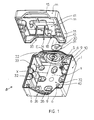
- a housing B of electrical equipment consisting mainly of a base 10 intended to receive the apparatus, a cover 11 and two crossing devices (or E tips) (only one of which is shown in this figure).
- the base 10 comprises of share a bottom wall 40 having orifices 32 through which said wall 40 is intended to be fixed by means of screws 33 on a bearing surface (s) such as a wall, and on the other hand walls side 1.
- Two of these side walls 1, opposite one another, have semi-openings 36 substantially V-shaped intended to receive the lower part said cable entries or end piece E.
- the cover 11 is constituted by an upper wall 41 and side walls m, two of which have a semi-opening 35 substantially in V shape intended to receive the upper part of one of the cable entries E.
- the end piece is housed partly in the base 10 and partly in the cover 11, which provides a low housing height B, while facilitating mounting and access to components in the housing B.
- the shape of the opening 35, 36 of the housing facilitates the connection of the cables to the components and access to the connection terminals.
- the cable entry E conforms to the invention consists of a rigid part 1 (for example made of rigid thermoplastic) of which the outer contour takes substantially the form of 2V inverted, and having an orifice central closed by a flexible membrane 2 (for example made of flexible thermoplastic), rigidly fixed to an inner surface of the rigid part 1.
- This rigid part 1 comprises also, at its two opposite ends, two so-called fixing tabs 5, intended to sliding to cooperate with two slides 6 formed on the inner surface of the wall of the base 10 intended to receive the input E, and thus form with the slides 6 means of fixing the cable entry in the housing B.
- these tabs 5 are arranged on the side and on the other side of a plane substantially perpendicular to the bearing surface (s) (or bottom wall 40) and passing through axis X of the opening of said end piece E.
- locking means comprising means latching or clips (not shown) provided partly on the legs 5 and partly in the backstage 6.
- the end piece E has on its inner face, at level of its rigid part, a rib 22 shaped so as to allow it to be grasped.
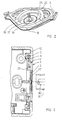
- the flexible crossing element 2 comprises a nipple 17 intended to be torn off manually or using a tool so as to release an orifice intended to receive a conduit or cable 30, 31.
- this nipple 17 has grooves 18 extending parallel to its longitudinal direction and intended to facilitate its gripping.
- this nipple 17 comprises at the base, a reinforcement 16 set back relative to the lip 19 and formed in such a way that the tearing located at the level of the wall 20 does not not damage the lip 19 which provides the seal in connection with the conduit 30, 31.
- the aforementioned tip (E) has the along its lower part, a flange 37 adapted to be housed in a groove 26 of the base 10 and intended to constrain the efforts of engagement and withdrawal of the conduit 30, 31.
- This flange 37 is extended by a tongue 8 capable of being received in the aforementioned groove 26 and intended to guide the end piece (E) during its mounting in the base (E).
- the end piece (E) has at its part lower, a seal 4 cooperating with a rib 29 of the base 10 so as to seal between the two parts.
- the end piece has at its upper part a rib 14 cooperating with a seal 12 provided on the cover 11, so as to seal between the end piece (E) and the cover 11.
- the rib 14 on the inlet deforms the seal 12 of the cover 11 according to a circular generator. It is thus possible to obtain a continuous seal on the cover.
- end piece (E) has a boss 25 capable of coming up against a rib 9 of the base 10, so as to limit the crushing of the seal 4.
- the installation of the crossing devices is carried out by introducing the tabs 5 of the inputs E in the slides 6 of the base E until the locking is achieved. Then the cover 11 is fixed to the base 10.
- the introduction of the cable or conduit 30, 31 inside the housing B is carried out after a pull has been exerted on the nipple 17 of the element of crossing 2 manually or using a tool.
- the flexible element 2 not comprising a teat, a simple push exerted with the thumb on the central part 45 will be enough to cause the release of the orifice.
- the entry can be lifted and slid along this conduit, the housing and the tube being fixed on their support.
- the shape of the end piece can be different, for example quadrangular.
- This device ensures a watertight entry of cable, conduit, cable gland or any tube in the housing.
- the entry and the housing form a rigid and waterproof.
- Such a sealed crossing device can be used for example in junction boxes, boxes, enclosures, connection plates for electrical cabinets.
Landscapes
- Engineering & Computer Science (AREA)
- Architecture (AREA)
- Civil Engineering (AREA)
- Structural Engineering (AREA)
- Installation Of Indoor Wiring (AREA)
- Casings For Electric Apparatus (AREA)
- Details Of Indoor Wiring (AREA)
- Insulators (AREA)
- Switch Cases, Indication, And Locking (AREA)
- Insertion, Bundling And Securing Of Wires For Electric Apparatuses (AREA)
- Coupling Device And Connection With Printed Circuit (AREA)
- Connector Housings Or Holding Contact Members (AREA)
- Mechanisms For Operating Contacts (AREA)
- Connection Or Junction Boxes (AREA)
Abstract
Description
Les pattes ainsi glissées dans les coulisses de l'embase ramènent le boítier dans son état initial après l'opération de fixation.
- la figure 1 est une vue en perspective illustrant un boítier d'appareillage électrique ouvert, équipé d'un dispositif de traversée (ou embout), conforme à une réalisation particulière de l'invention,
- la figure 2 est une vue en perspective du dispositif de traversée vu côté intérieur,
- la figure 3 est une vue en coupe du boítier, suivant un plan parallèle à sa paroi de fond,
- la figure 4 est une vue en coupe du boítier suivant un plan longitudinal médian perpendiculaire à sa paroi de fond,
- la figure 5 est une vue partielle d'un dispositif de traversée, conforme à une autre réalisation de l'invention, et
- la figure 6 illustre en perspective l'entrée de câble de l'invention, vue de l'extérieur.
Claims (16)
- Dispositif de traversée pour un boítier ou une enveloppe d'un équipement électrique, ledit boítier comprenant une embase et un couvercle, ladite embase comprenant une paroi de fond par laquelle ledit boítier est destiné à être fixé sur une surface d'appui et des parois latérales, ledit dispositif comprenant un embout de fermeture susceptible d'être fixé de manière amovible et étanche dans une ouverture de forme conjuguée ménagée dans l'une des parois latérales du boítier grâce à des moyens de fixation prévus en partie sur le boítier et en partie sur l'embout, de manière à autoriser le passage étanche d'un élément de raccordement, notamment un conduit ou un câble,
caractérisé en ce que les moyens de fixation précités comprennent d'une part, au moins une patte (5) (ou coulisse (6)) prévue sur l'embout apte à coopérer à coulissement avec au moins une coulisse (6) (ou respectivement, patte (5)) appartenant au boítier B, (la)lesdites patte(s) et coulisse(s) s'étendant sensiblement perpendiculairement à la paroi de fond (40) dudit boítier B de manière à rigidifier ledit boítier notamment pendant sa fixation sur la surface d'appui précitée (s), et d'autre part, des moyens de verrouillage de l'embout E sur le boítier B. - Dispositif selon la revendication 1, caractérisé en ce que les pattes (5) (ou coulisses (6)) sont au nombre de deux et sont situés de part et d'autre d'un plan sensiblement perpendiculaire à la surface d'appui précitée (s) et passant par l'axe X dudit embout (E).
- Dispositif selon la revendication 2, caractérisé en ce que les pattes (5) et coulisses (6) sont situées respectivement aux deux extrémités de l'embout (E).
- Dispositif selon l'une quelconque des revendication précédentes, caractérisé en ce que les parties inférieure et supérieure de l'embout E présentent chacune un contour extérieur sensiblement en forme de V, et sont adaptées pour être reçues respectivement dans des semi-ouvertures (36, 35) de forme correspondante de l'embase (10) et du couvercle (11).
- Dispositif selon l'une quelconque des revendications précédentes, caractérisé en ce que l'embout précité E comporte sur sa face intérieure une nervure (22) conformée de manière à permettre sa préhension.
- Dispositif selon l'une quelconque des revendications précédentes, caractérisé en ce que les moyens de verrouillage comprennent des moyens d'encliquetage prévus en partie sur les pattes (5) et en partie dans les coulisses (6).
- Dispositif selon l'une quelconque des revendications précédentes, caractérisé en ce que ledit embout (E) comprend une partie rigide (1) supportant les moyens de fixation précités et un élément souple de traversée (2) disposé à l'intérieur de la première partie (1) en étant fixée rigidement à une surface intérieure de celle-ci.
- Dispositif selon la revendication 7, caractérisé en ce que l'élément de traversée précitée (2) comporte une tétine (17) destinée à être arrachée manuellement ou à l'aide d'un outil, de manière à libérer un orifice destiné à recevoir un conduit (30, 31).
- Dispositif selon la revendication 8, caractérisé en ce que la tétine précitée (3) comporte des rainures (18) s'étendant parallèlement à sa direction longitudinale et destinées à faciliter sa préhension.
- Dispositif selon la revendication 8 ou 9, caractérisé en ce que la tétine (17) comporte à sa base un renforcement (16) en retrait vers l'intérieur du boítier B par rapport à une lèvre (19) destinée à réaliser l'étanchéité entre l'embout (E) et le conduit (30, 31), afin que le déchirement de la tétine (17) ne détériore pas la lèvre (19).
- Dispositif selon l'une quelconque des revendications précédentes, caractérisé en ce que l'embout précité (E) comporte le long de sa partie inférieure, une collerette (37) apte à venir se loger dans une rainure (26) de l'embase (10) et destinée à contraindre les efforts d'engagement et de retrait du conduit (30, 31).
- Dispositif selon la revendication 11, caractérisé en ce que la collerette (37) est prolongée par une languette (8) apte à être reçue dans la rainure précitée (26) et destinée à guider l'embout (E) lors de son montage dans l'embase (E).
- Dispositif selon l'une quelconque des revendications précédentes, caractérisé en ce que l'embout (E) comporte à sa partie inférieure, un joint d'étanchéité (4) coopérant avec une nervure (29) de l'embase (10) de manière à réaliser l'étanchéité entre les deux pièces.
- Dispositif selon l'une quelconque des revendications précédentes, caractérisé en ce que l'embout (E) comporte à sa partie supérieure une nervure (14) coopérant avec un joint (12) prévu sur le couvercle (11), de manière à réaliser l'étanchéité entre l'embout (E) et le couvercle (11).
- Dispositif selon la revendication 13 ou 14, caractérisé en ce que l'embout (E) comporte un bossage (25) apte à venir buter sur une nervure (9) de l'embase (10), de manière à limiter l'écrasement du joint (4).
- Boítier d'un équipement électrique, caractérisé en ce qu'il comporte au moins un orifice (35, 36), destiné à recevoir un dispositif selon l'une quelconque des revendications 1 à 15.
Applications Claiming Priority (2)
| Application Number | Priority Date | Filing Date | Title |
|---|---|---|---|
| FR9715503A FR2771844B1 (fr) | 1997-12-02 | 1997-12-02 | Dispositif de traversee, notamment pour boitier d'equipement electrique |
| FR9715503 | 1997-12-02 |
Publications (2)
| Publication Number | Publication Date |
|---|---|
| EP0921546A1 true EP0921546A1 (fr) | 1999-06-09 |
| EP0921546B1 EP0921546B1 (fr) | 2006-01-11 |
Family
ID=9514318
Family Applications (1)
| Application Number | Title | Priority Date | Filing Date |
|---|---|---|---|
| EP98410129A Expired - Lifetime EP0921546B1 (fr) | 1997-12-02 | 1998-11-10 | Dispositif de traverse, notamment pour boîtier d'équipement électrique |
Country Status (6)
| Country | Link |
|---|---|
| EP (1) | EP0921546B1 (fr) |
| AT (1) | ATE315830T1 (fr) |
| DE (1) | DE69833174T2 (fr) |
| ES (1) | ES2256925T3 (fr) |
| FR (1) | FR2771844B1 (fr) |
| PL (1) | PL193042B1 (fr) |
Cited By (10)
| Publication number | Priority date | Publication date | Assignee | Title |
|---|---|---|---|---|
| FR2881285A1 (fr) * | 2005-01-25 | 2006-07-28 | Legrand France | Boitier electrique dote d'un element de paroi amovible |
| WO2012084168A1 (fr) * | 2010-12-22 | 2012-06-28 | Schneider Electric Industries Sas | Insert mural |
| CN104299819A (zh) * | 2014-07-25 | 2015-01-21 | 陈胜森 | 一种具有微动结构的86盒开关面板的结构 |
| EP3840150A1 (fr) * | 2019-12-20 | 2021-06-23 | Legrand France | Embout passe-cable etanche,boite electrique comprenant un tel embout et appareillage electrique comportant un mecanisme d'appareillage rapporte dans une telle boite electrique |
| WO2021122050A1 (fr) * | 2019-12-20 | 2021-06-24 | Legrand France | Embout passe-cable etanche,boite electrique comprenant un tel embout passe-cable et appareillage electrique comportant un mecanisme d'appareillage rapporte dans une telle boite electrique |
| FR3105621A1 (fr) * | 2019-12-20 | 2021-06-25 | Legrand France | Boîte électrique munie d’un joint d’étanchéité |
| FR3105614A1 (fr) * | 2019-12-20 | 2021-06-25 | Legrand France | Boîte électrique et appareillage électrique associé |
| WO2023076160A1 (fr) * | 2021-10-25 | 2023-05-04 | Bloomsburg Carpet Industries, Inc. | Boîte de jonction modulaire |
| RU2819700C1 (ru) * | 2019-12-20 | 2024-05-23 | Легран Франс | Герметичный кабельный ввод, электрическая коробка, содержащая такой кабельный ввод, и электрический прибор, содержащий механизм прибора, установленный в такой электрической коробке |
| EP3840149B1 (fr) * | 2019-12-16 | 2025-08-06 | Legrand France | Appareillage comprenant un bloc de finition amovible |
Families Citing this family (1)
| Publication number | Priority date | Publication date | Assignee | Title |
|---|---|---|---|---|
| DE102011001985C5 (de) | 2011-04-12 | 2016-11-03 | R. Stahl Schaltgeräte GmbH | Durchführungsanordnung mit hoher Sicherheit |
Citations (5)
| Publication number | Priority date | Publication date | Assignee | Title |
|---|---|---|---|---|
| CH375056A (de) * | 1958-09-22 | 1964-02-15 | Licentia Gmbh | Schutzkappe mit Schalter und Überlastschutz an einem Elektrogerät |
| DE2240086A1 (de) * | 1972-08-16 | 1974-03-07 | Merten Geb | Leitungseinfuehrung an feuchtigkeitsgeschuetzten gehaeusen fuer elektrische installationsgeraete |
| DE8600635U1 (de) * | 1986-01-13 | 1986-02-27 | Siemens AG, 1000 Berlin und 8000 München | Gehäuse für wassergeschützte Installationsgeräte |
| FR2689331A1 (fr) * | 1992-03-27 | 1993-10-01 | Legrand Sa | Embout à rapporter sur une paroi pour y constituer une sortie de câble. |
| DE4300521A1 (de) * | 1993-01-12 | 1994-07-14 | Weidmueller Interface | Kabelabdichtungs- und Zugentlastungsvorrichtung für Wanddurchbrüche |
-
1997
- 1997-12-02 FR FR9715503A patent/FR2771844B1/fr not_active Expired - Fee Related
-
1998
- 1998-11-10 EP EP98410129A patent/EP0921546B1/fr not_active Expired - Lifetime
- 1998-11-10 AT AT98410129T patent/ATE315830T1/de active
- 1998-11-10 DE DE69833174T patent/DE69833174T2/de not_active Expired - Lifetime
- 1998-11-10 ES ES98410129T patent/ES2256925T3/es not_active Expired - Lifetime
- 1998-11-27 PL PL329968A patent/PL193042B1/pl unknown
Patent Citations (5)
| Publication number | Priority date | Publication date | Assignee | Title |
|---|---|---|---|---|
| CH375056A (de) * | 1958-09-22 | 1964-02-15 | Licentia Gmbh | Schutzkappe mit Schalter und Überlastschutz an einem Elektrogerät |
| DE2240086A1 (de) * | 1972-08-16 | 1974-03-07 | Merten Geb | Leitungseinfuehrung an feuchtigkeitsgeschuetzten gehaeusen fuer elektrische installationsgeraete |
| DE8600635U1 (de) * | 1986-01-13 | 1986-02-27 | Siemens AG, 1000 Berlin und 8000 München | Gehäuse für wassergeschützte Installationsgeräte |
| FR2689331A1 (fr) * | 1992-03-27 | 1993-10-01 | Legrand Sa | Embout à rapporter sur une paroi pour y constituer une sortie de câble. |
| DE4300521A1 (de) * | 1993-01-12 | 1994-07-14 | Weidmueller Interface | Kabelabdichtungs- und Zugentlastungsvorrichtung für Wanddurchbrüche |
Cited By (17)
| Publication number | Priority date | Publication date | Assignee | Title |
|---|---|---|---|---|
| FR2881285A1 (fr) * | 2005-01-25 | 2006-07-28 | Legrand France | Boitier electrique dote d'un element de paroi amovible |
| WO2006079706A1 (fr) * | 2005-01-25 | 2006-08-03 | Legrand France | Boitier electrique dote d’un element de paroi amovible |
| WO2012084168A1 (fr) * | 2010-12-22 | 2012-06-28 | Schneider Electric Industries Sas | Insert mural |
| RU2578670C2 (ru) * | 2010-12-22 | 2016-03-27 | Шнейдер Электрик Эндюстри Сас | Стенная вставка |
| CN104299819A (zh) * | 2014-07-25 | 2015-01-21 | 陈胜森 | 一种具有微动结构的86盒开关面板的结构 |
| EP3840149B1 (fr) * | 2019-12-16 | 2025-08-06 | Legrand France | Appareillage comprenant un bloc de finition amovible |
| FR3105622A1 (fr) * | 2019-12-20 | 2021-06-25 | Legrand France | Embout passe-câble étanche, boîte électrique comprenant un tel embout et appareillage électrique comportant un mécanisme d'appareillage rapporté dans une telle boîte électrique |
| FR3105623A1 (fr) * | 2019-12-20 | 2021-06-25 | Legrand France | Embout passe-câble étanche, boîte électrique comprenant un tel embout passe-câble et appareillage électrique comportant un mécanisme d'appareillage rapporté dans une telle boîte électrique |
| WO2021122050A1 (fr) * | 2019-12-20 | 2021-06-24 | Legrand France | Embout passe-cable etanche,boite electrique comprenant un tel embout passe-cable et appareillage electrique comportant un mecanisme d'appareillage rapporte dans une telle boite electrique |
| FR3105621A1 (fr) * | 2019-12-20 | 2021-06-25 | Legrand France | Boîte électrique munie d’un joint d’étanchéité |
| FR3105614A1 (fr) * | 2019-12-20 | 2021-06-25 | Legrand France | Boîte électrique et appareillage électrique associé |
| CN114830476A (zh) * | 2019-12-20 | 2022-07-29 | 勒格朗法国公司 | 密封式电缆输入箍件、包括这种电缆输入箍件的电气壳体和包括附接至这种电气壳体的电气机构的电气设备 |
| CN114830476B (zh) * | 2019-12-20 | 2024-05-07 | 勒格朗法国公司 | 密封式电缆输入箍件、包括这种电缆输入箍件的电气壳体和包括附接至这种电气壳体的电气机构的电气设备 |
| RU2819700C1 (ru) * | 2019-12-20 | 2024-05-23 | Легран Франс | Герметичный кабельный ввод, электрическая коробка, содержащая такой кабельный ввод, и электрический прибор, содержащий механизм прибора, установленный в такой электрической коробке |
| EP3840150A1 (fr) * | 2019-12-20 | 2021-06-23 | Legrand France | Embout passe-cable etanche,boite electrique comprenant un tel embout et appareillage electrique comportant un mecanisme d'appareillage rapporte dans une telle boite electrique |
| WO2023076160A1 (fr) * | 2021-10-25 | 2023-05-04 | Bloomsburg Carpet Industries, Inc. | Boîte de jonction modulaire |
| US11784476B2 (en) | 2021-10-25 | 2023-10-10 | Bloomsburg Carpet Industries, Inc. | Modular junction box |
Also Published As
| Publication number | Publication date |
|---|---|
| ES2256925T3 (es) | 2006-07-16 |
| FR2771844A1 (fr) | 1999-06-04 |
| EP0921546B1 (fr) | 2006-01-11 |
| DE69833174D1 (de) | 2006-04-06 |
| FR2771844B1 (fr) | 2000-01-07 |
| DE69833174T2 (de) | 2006-08-03 |
| PL329968A1 (en) | 1999-06-07 |
| ATE315830T1 (de) | 2006-02-15 |
| PL193042B1 (pl) | 2007-01-31 |
Similar Documents
| Publication | Publication Date | Title |
|---|---|---|
| EP0921546B1 (fr) | Dispositif de traverse, notamment pour boîtier d'équipement électrique | |
| EP0470010A1 (fr) | Coffret étanche d'appareillage électrique | |
| EP0653825B1 (fr) | Dispositif de traversée étanche à membrane souple et opercule jetable | |
| EP0813663B1 (fr) | Dispositif de raccordement d'angle pour conduit a corps en gouttiere et couvercle tel que moulure, plinthe ou goulotte, notamment pour appareillage electrique | |
| FR2580860A1 (fr) | Cache-borne pour un appareil electrique basse tension a boitier isolant modulaire | |
| EP3123579B1 (fr) | Dispositif de traversée étanche de faisceau électrique | |
| FR2710790A1 (fr) | Dispositif de traversée étanche. | |
| EP0647004B1 (fr) | Boîtier pour équipement électrique | |
| EP1160951A1 (fr) | Boíte de dérivation pour goulottes, en particulier pour passages de plancher | |
| EP0746072B1 (fr) | Pupitre pour le logement notamment d'appareillages électriques | |
| EP1860671A1 (fr) | Passe-barre | |
| EP0575263B1 (fr) | Goulotte pour dispositif de distribution électrique | |
| FR2653654A1 (fr) | Boitier a raccord tournant pour suceur d'aspirateur. | |
| EP2113977B1 (fr) | Accessoire de montage d'un bloc électrique dans un conduit de cheminement de câbles et ensemble électrique comprenant un bloc électrique ainsi qu'un tel accessoire | |
| EP1843440A1 (fr) | Accessoire de raccordement étanche avec une membrane souple entre un conduit électrique et un boîtier d'appareillage | |
| FR2774522A1 (fr) | Support de reception d'un bloc-prise pour plinthe de distribution | |
| FR2628577A1 (fr) | Coffret de branchement en matiere plastique pour cables electriques | |
| FR2605152A1 (fr) | Accessoire de derivation pour conduit de cablage | |
| BE1003141A6 (fr) | Boite sous plancher. | |
| EP0739070B1 (fr) | Dispositif de connexion électrique pour le raccordement d'un appareil électrique au réseau | |
| EP1843439B1 (fr) | Accessoire de raccordement pour conduit et ensemble comprenant un conduit recevant un tel accessoire | |
| FR2826091A1 (fr) | Piece d'etancheite pour la traversee d'un faisceau electrique a travers l'ouverture d'une paroi | |
| EP1616735A2 (fr) | Dispositif de protection d'un passage d'air d'une boîte à eau de véhicule automobile, et boîte à eau correspondante | |
| FR2461431A3 (fr) | Radiomicrophone a plusieurs emplois avec circuit imprime extractible | |
| WO2002013346A1 (fr) | Boitier etanche pour l'encastrement d'un appareillage dans une paroi |
Legal Events
| Date | Code | Title | Description |
|---|---|---|---|
| PUAI | Public reference made under article 153(3) epc to a published international application that has entered the european phase |
Free format text: ORIGINAL CODE: 0009012 |
|
| AK | Designated contracting states |
Kind code of ref document: A1 Designated state(s): AT BE CH DE ES GB IT LI |
|
| AX | Request for extension of the european patent |
Free format text: AL;LT;LV;MK;RO;SI |
|
| RAP1 | Party data changed (applicant data changed or rights of an application transferred) |
Owner name: SCHNEIDER ELECTRIC INDUSTRIES SA |
|
| 17P | Request for examination filed |
Effective date: 19991105 |
|
| AKX | Designation fees paid |
Free format text: AT BE CH DE ES GB IT LI |
|
| RAP1 | Party data changed (applicant data changed or rights of an application transferred) |
Owner name: SCHNEIDER ELECTRIC INDUSTRIES SA |
|
| RAP1 | Party data changed (applicant data changed or rights of an application transferred) |
Owner name: SCHNEIDER ELECTRIC INDUSTRIES SAS |
|
| 17Q | First examination report despatched |
Effective date: 20040810 |
|
| GRAP | Despatch of communication of intention to grant a patent |
Free format text: ORIGINAL CODE: EPIDOSNIGR1 |
|
| GRAS | Grant fee paid |
Free format text: ORIGINAL CODE: EPIDOSNIGR3 |
|
| GRAA | (expected) grant |
Free format text: ORIGINAL CODE: 0009210 |
|
| AK | Designated contracting states |
Kind code of ref document: B1 Designated state(s): AT BE CH DE ES GB IT LI |
|
| PG25 | Lapsed in a contracting state [announced via postgrant information from national office to epo] |
Ref country code: IT Free format text: LAPSE BECAUSE OF FAILURE TO SUBMIT A TRANSLATION OF THE DESCRIPTION OR TO PAY THE FEE WITHIN THE PRESCRIBED TIME-LIMIT;WARNING: LAPSES OF ITALIAN PATENTS WITH EFFECTIVE DATE BEFORE 2007 MAY HAVE OCCURRED AT ANY TIME BEFORE 2007. THE CORRECT EFFECTIVE DATE MAY BE DIFFERENT FROM THE ONE RECORDED. Effective date: 20060111 |
|
| REG | Reference to a national code |
Ref country code: CH Ref legal event code: EP |
|
| GBT | Gb: translation of ep patent filed (gb section 77(6)(a)/1977) |
Effective date: 20060220 |
|
| REF | Corresponds to: |
Ref document number: 69833174 Country of ref document: DE Date of ref document: 20060406 Kind code of ref document: P |
|
| REG | Reference to a national code |
Ref country code: ES Ref legal event code: FG2A Ref document number: 2256925 Country of ref document: ES Kind code of ref document: T3 |
|
| PLBE | No opposition filed within time limit |
Free format text: ORIGINAL CODE: 0009261 |
|
| STAA | Information on the status of an ep patent application or granted ep patent |
Free format text: STATUS: NO OPPOSITION FILED WITHIN TIME LIMIT |
|
| 26N | No opposition filed |
Effective date: 20061012 |
|
| PGFP | Annual fee paid to national office [announced via postgrant information from national office to epo] |
Ref country code: AT Payment date: 20141027 Year of fee payment: 17 |
|
| REG | Reference to a national code |
Ref country code: AT Ref legal event code: MM01 Ref document number: 315830 Country of ref document: AT Kind code of ref document: T Effective date: 20151110 |
|
| PG25 | Lapsed in a contracting state [announced via postgrant information from national office to epo] |
Ref country code: AT Free format text: LAPSE BECAUSE OF NON-PAYMENT OF DUE FEES Effective date: 20151110 |
|
| PGFP | Annual fee paid to national office [announced via postgrant information from national office to epo] |
Ref country code: DE Payment date: 20170201 Year of fee payment: 19 |
|
| PGFP | Annual fee paid to national office [announced via postgrant information from national office to epo] |
Ref country code: IT Payment date: 20171123 Year of fee payment: 20 Ref country code: GB Payment date: 20171108 Year of fee payment: 20 Ref country code: ES Payment date: 20171201 Year of fee payment: 20 Ref country code: CH Payment date: 20171114 Year of fee payment: 20 Ref country code: BE Payment date: 20170925 Year of fee payment: 20 |
|
| REG | Reference to a national code |
Ref country code: DE Ref legal event code: R119 Ref document number: 69833174 Country of ref document: DE |
|
| PG25 | Lapsed in a contracting state [announced via postgrant information from national office to epo] |
Ref country code: DE Free format text: LAPSE BECAUSE OF NON-PAYMENT OF DUE FEES Effective date: 20180602 |
|
| REG | Reference to a national code |
Ref country code: CH Ref legal event code: PL |
|
| REG | Reference to a national code |
Ref country code: GB Ref legal event code: PE20 Expiry date: 20181109 |
|
| REG | Reference to a national code |
Ref country code: BE Ref legal event code: MK Effective date: 20181110 |
|
| PG25 | Lapsed in a contracting state [announced via postgrant information from national office to epo] |
Ref country code: GB Free format text: LAPSE BECAUSE OF EXPIRATION OF PROTECTION Effective date: 20181109 |
|
| REG | Reference to a national code |
Ref country code: ES Ref legal event code: FD2A Effective date: 20200721 |
|
| PG25 | Lapsed in a contracting state [announced via postgrant information from national office to epo] |
Ref country code: ES Free format text: LAPSE BECAUSE OF EXPIRATION OF PROTECTION Effective date: 20181111 |