EP0921703A2 - Bild-Paketkommunikationssystem - Google Patents
Bild-Paketkommunikationssystem Download PDFInfo
- Publication number
- EP0921703A2 EP0921703A2 EP98118885A EP98118885A EP0921703A2 EP 0921703 A2 EP0921703 A2 EP 0921703A2 EP 98118885 A EP98118885 A EP 98118885A EP 98118885 A EP98118885 A EP 98118885A EP 0921703 A2 EP0921703 A2 EP 0921703A2
- Authority
- EP
- European Patent Office
- Prior art keywords
- image
- transmission
- packet
- frame
- clock
- Prior art date
- Legal status (The legal status is an assumption and is not a legal conclusion. Google has not performed a legal analysis and makes no representation as to the accuracy of the status listed.)
- Granted
Links
Images



Classifications
-
- H—ELECTRICITY
- H04—ELECTRIC COMMUNICATION TECHNIQUE
- H04L—TRANSMISSION OF DIGITAL INFORMATION, e.g. TELEGRAPHIC COMMUNICATION
- H04L49/00—Packet switching elements
- H04L49/30—Peripheral units, e.g. input or output ports
- H04L49/3081—ATM peripheral units, e.g. policing, insertion or extraction
-
- H—ELECTRICITY
- H04—ELECTRIC COMMUNICATION TECHNIQUE
- H04Q—SELECTING
- H04Q11/00—Selecting arrangements for multiplex systems
- H04Q11/04—Selecting arrangements for multiplex systems for time-division multiplexing
- H04Q11/0428—Integrated services digital network, i.e. systems for transmission of different types of digitised signals, e.g. speech, data, telecentral, television signals
- H04Q11/0478—Provisions for broadband connections
-
- H—ELECTRICITY
- H04—ELECTRIC COMMUNICATION TECHNIQUE
- H04L—TRANSMISSION OF DIGITAL INFORMATION, e.g. TELEGRAPHIC COMMUNICATION
- H04L12/00—Data switching networks
- H04L12/54—Store-and-forward switching systems
- H04L12/56—Packet switching systems
- H04L12/5601—Transfer mode dependent, e.g. ATM
- H04L2012/5614—User Network Interface
- H04L2012/5616—Terminal equipment, e.g. codecs, synch.
-
- H—ELECTRICITY
- H04—ELECTRIC COMMUNICATION TECHNIQUE
- H04L—TRANSMISSION OF DIGITAL INFORMATION, e.g. TELEGRAPHIC COMMUNICATION
- H04L12/00—Data switching networks
- H04L12/54—Store-and-forward switching systems
- H04L12/56—Packet switching systems
- H04L12/5601—Transfer mode dependent, e.g. ATM
- H04L2012/5638—Services, e.g. multimedia, GOS, QOS
- H04L2012/5646—Cell characteristics, e.g. loss, delay, jitter, sequence integrity
- H04L2012/5649—Cell delay or jitter
-
- H—ELECTRICITY
- H04—ELECTRIC COMMUNICATION TECHNIQUE
- H04L—TRANSMISSION OF DIGITAL INFORMATION, e.g. TELEGRAPHIC COMMUNICATION
- H04L12/00—Data switching networks
- H04L12/54—Store-and-forward switching systems
- H04L12/56—Packet switching systems
- H04L12/5601—Transfer mode dependent, e.g. ATM
- H04L2012/5672—Multiplexing, e.g. coding, scrambling
- H04L2012/5674—Synchronisation, timing recovery or alignment
Definitions
- the present invention relates to a packet communications system, and more particularly to a communications system for sending and receiving image information and other information in real time over a high-speed packet network synchronizing between a transmitter side and a receiver side.
- ATM Asynchronous transfer mode
- clocks at transmitter and receiver terminals are synchronized in subordination to a network clock of a high-speed packet network.
- image data are transmitted in conjunction with transmission frame synchronizing signals that are generated based on the subordinately synchronized clock.
- reproduction-side synchronization is effected on the frames using both reception frame synchronizing signals generated on the basis of a subordinately synchronized clock and transmission-reproduction frame synchronizing signals generated on the basis of timing packets added to the transmission image packets.
- synchronization packets added to transmitted image signals are detected on the receiver terminal, as in the first reference, and image frame synchronizing signals and image clocks are generated from moving averages of arrival times of the synchronizing information based on the synchronization packets, and the synchronization of image frames is thereby achieved.
- the third reference provides a synchronization method using statistical characteristics of adaptive differential PCM (ADPCM) signals constituting transmission data.
- ADPCM adaptive differential PCM
- the fundamental problem with the conventional systems disclosed in the first and the second references resides in the fact that the synchronization signals are generated on the receiver side based on unstable synchronization packets which have been detected on the receiver side.
- the present invention has been developed to solve the problems inherent to the conventional systems, and an essential object of the present invention is to provide an improvement of an image packet communications system.
- an image packet communications system for communicating image data information in real time between a transmitter side and a received side through a network, wherein the transmitter comprises:
- the transmitter further comprises a transmission standard signal generator for generating a transmission standard signal based on the transmission clock and the packet generator generates the image packets with image packet headers attached thereto to produce transmission packets, with reference to the transmission standard signal
- the packet receiver is comprised of a separator means for separating the image packets and the image packet headers from each other so that the buffer controller generates an address signal based on information of the image packet headers supplied from the packet receiver.
- the buffer controller is supplied with a reference signal (REF) from the outside as a frame standard signal, and when detecting that a time differential between the reception standard signal generated based on the reception clock and the reference signal (REF) input from the outside exceeds a predetermined value, the writing and reading of the image packets to and from the buffer memory group is so controlled such that the image data output from the buffer memory group has a suitable volume for the reference signal.
- REF reference signal
- the transmitter further comprises a buffer memory group for storing the input image signals and a buffer controller for controlling the writing and reading of the image signals to and from the buffer memory group, and wherein the buffer controller is supplied with a reference signal (REF) from the outside as a frame standard signal, and when detecting that a time differential between the transmission standard signal generated by the transmission standard signal generator and the reference signal (REF) input from the outside exceeds a predetermined value, the writing and reading of the input image signals to and from the buffer memory group is so controlled such that the image data output from the buffer memory group has a suitable volume for the reference signal.
- a reference signal REF
- the network is comprised of one or more packet switching devices, each packet switching device including:
- the packet generator completes the transmissions of the image packets and packet headers belonging within a period of said transmission standard signal, within a time period obtained by subtracting the maximum network fluctuation from said transmission standard signal.
- transmissions are conducted with a clock subordinately synchronized to the network clock and frame signals generated based on the clock established as the synchronization standard at the transmitter terminal, and in the meanwhile, transmissions are conducted with a clock subordinately synchronized to the network clock and frame signals generated based on the clock established as the synchronization standard at the receiver end, thus affording the benefit of being able to build a communications system where the synchronization between the transmitter end and the receiver end can be guaranteed.
- the image packets are transmitted after attaching image packet headers thereto, wherefore, even when a packet loss or error occurs in the network, and a transmission packet is lost, that transmission packet error has no effect on the other transmission packets, and normally received transmission packets are securely received and output. Accordingly, an effect is afforded in that high image quality can be maintained in the transmissions even when packet losses or errors occur.
- the synchronization period of the network clock in the high-speed packet network differs from the period of the reference signal at the receiver side, it is possible to adjust the image data volume so that the image data received from the network are made suitable to the reference signal period. Accordingly, it is possible to build systems wherein equipment synchronized to the network clock is connected to equipment synchronized to the reference signal, thereby affording the effect of being able to guarantee frame synchronization for all equipment in the system.
- the volume of image data can be adjusted so that the image data input synchronized to the reference signal are made suitable to the period of the network clock.
- This makes it possible to interconnect equipment synchronized to the reference signal and equipment synchronized to the network clock, thus affording the effect of being able to guarantee the frame synchronization of all equipment in the system.
- the image data volume is adjusted in frame units, so that high image quality can be preserved.
- an image packet communications system assuring the frame synchronization of all equipment included in the transmitter, the high-speed packet network, and the receiver, thereby affording the effect of maintaining high image quality.
- the image data in each frame are transmitted without fail within the frame period, even when fluctuations occur in the high-speed packet network, thereby affording the effect of realizing an image packet communications system assuring high image quality.
- the first, second, third, fourth, and fifth aspects of the present invention all afford the benefit of being realizable in a simple configuration. Furthermore, the present invention can be implemented without detecting any kind of signal from the data, thus providing the benefit of being applicable irrespective of the data being communicated.
- ATM asynchronous transfer mode communications
- An exemplary ATM standard conforms to any of the following but shall not be limited to: ITU-T, Q.2931; ITU-T, I.363; and ATM User-Network Interface Specification Version 3.0 (UNI3.0), Version 3.1 (UNI3.1), or Version 4.0 (UNI4.0), of The ATM Forum.
- a transfer capacity of 155 megabits per second is taken as an example.
- SONET Synchronous Optical Network
- the specifications for SONET (Synchronous Optical Network), adopted by the ATM at the physical level, are set forth by the American National Standards Institute (ANSI) in T1E1.2/94-002R1 and T1.105.
- the examples used for the data in communication are image data, audio data, and additional information, based on specifications for a commercial digital VCR.
- the DVC specification is set forth in "Specifications of Consumer-Use Digital VCRs Using 6.3mm Magnetic Tape,” HD Digital VCR Conference, December, 1994 (hereinafter referred to as Reference 4).
- the specifications for the digital interface thereof are set forth in "Specifications of Digital Interface for Consumer Electric Audio/Video Equipment,” HD Digital VCR Conference, December, 1995 (hereinafter referred to as Reference 5).
- the transfer capacity of the digital interface in the DVC specification is 28.8 megabits per second (i.e., 120 kilobytes per frame), inclusive of audio data and additional information.
- the description is made in a case of assuming that DVC-specification data are communicated in frame units. Therefore, in the present invention, in terms of input image signals and output image signals, the system transmits 120 kilobytes in one frame period.
- both audio signals and additional signals are handled simultaneously with image signals.
- These signals are transmitted in a superimposed or multiplexed state in the image signals, referenced to the short time unit (frame time) of the image signals.
- frame time short time unit
- every signals are described in terms of the image signals.
- the transmission data is not limited to DVC-specification data and the system may use a transmission time unit other than the frame unit, such as the field unit or some other time unit.
- Fig. 1 shows a schematic construction of an image packet communications system of the first embodiment, where a transmitter 101 is fed with input image signals and converts them into packets (ATM cells), and sends out the ATM cell packets over the ATM network.
- the transmitter 101 includes a transmission image clock generator 102, transmission standard signal generator 103, and packet generator 104.
- image signals based on the DVC specification are used as the input signals applied to the transmitter 101.
- a receiver 105 reconfigures image signals from the packets (ATM cells) received from the ATM network.
- the receiver 105 includes a reception image clock generator 106, packet receiver 107, a buffer group unit 108, and buffer controller 109.
- Reference numeral 110 denotes a high-speed packet network, which is comprised of, for example, an ATM network configured with ATM changeover switching devices (ATM switches) in the embodiments of the present invention.
- the transmitter 101 and the receiver 105 are connected through the high-speed packet network 110.
- the high-speed packet network 110 is synchronized throughout the entire network.
- ATM communications are effected on the premise that the SONET specification, for example, is used as a physical layer thereof.
- SONET a SONET frame made up of 9x270 bytes is transmitted every 125 microseconds. Therefore, the high-speed packet network 110 is synchronized with reference to 125-microsecond signals.
- a clock synchronized to a SONET frame is called as "network clock”.
- single connecting ports between the transmitter 101 and the high-speed packet network 110 are labeled as Tp1 and Rp1.
- the ATM communications are full duplex communications, with two ports for sending and receiving at each port.
- Tp1 (for sending) and Rp1 (for receiving) constitute one pair.
- a single connecting port between the receiver 105 and the high-speed packet network 110 is labeled Rp2.
- Rp2 there is also a sending port paired with the receiving port Rp2, but it is not indicated in Fig. 1 for brevity.
- the transmission image clock generator 102 In the transmitter 101, the transmission image clock generator 102 generates a transmission image clock CLK1 that is subordinately synchronized to a network clock applied through the terminal port Rp1 from the high-speed packet network. Thus, the transmission image clock is generated based on the network clock which is network-synchronized.
- a SONET frame is detected every 125 microseconds for the data received through the port Rp1, and therefore, by using PLL circuitry, it is easy to generate a clock (CLK1) that is subordinated to the network synchronization.
- the transmission standard signal generator 103 generates, based on the transmission image clock CLK1, a transmission synchronous frame signal (FLM1) serving as a transmission standard signal. Accordingly, the transmission synchronous frame signal (FLM1) is an accurate frame signal that is synchronized with the network clock, where the frame signal FLM1 can be easily configured using a counter (not shown).
- the transmission standard signal generator means 103 may be included in the transmission image clock generator 102.
- the transmission image clock CLK1 is also applied to the packet generator 104, so that the packet generator 104 generates image packets from the input image signals based on the timing of the transmission image clock CLK1, using the frame signal FLM1 as a frame reference. Then, the packet generator 104 attaches image packet headers to the image packets, and the resultant image packets are sent out to the network through the Tp1 port with the timing synchronized to the SONET frame. In this arrangement, it goes without saying that the ports Tp1 and Rp1 are synchronized with each other.
- the reception image clock generator 106 generates a reception image clock (CLK2) that is subordinately synchronized to the network clock, just as the transmission image clock generator 102, based on the synchronized network clock input through the Rp2 port. Since the reception chock CLK2 is subordinately synchronized to the network clock, therefore, the reception clock is synchronized with the transmission image clock CLK1.
- the packet receiver 107 separates the image packet headers from the image packets received through the Rp2 port, and sends the image packet headers to the buffer controller 109, while sending the image packets to the buffer group 108.
- the buffer group 108 is made up of frame memories.
- the buffer controller 109 Upon receipt of the image packet headers, the buffer controller 109 generates addresses (ADRS) in the frame memories for storing the received image packets, and also generates a frame signal (FLM2) for switching between the two frame memories and effecting the frame timing.
- ADRS addresses
- FLM2 frame signal
- the buffer group 108 based on the addresses ADRS and frame signal FLM2, stores one frame of image data, and outputs those data as output image signals.
- the frame memories of the buffer group 108 having the double memory structure, are switched over with every frame between storing of the received image packets and generating of the image data stored in frame units.
- Fig. 2 shows a timing chart representing the operations of the image packet communications system. The operations of the system shown in Fig. 1 are now described in detail with reference to Fig. 2.
- reference numeral 201 denotes a transmission synchronous frame signal (FLM1)
- 202 denotes an input image signal.
- the data volume of the input image signal is fixed for each frame, and is inputted to the transmitter 101 synchronously with the transmission synchronous frame signal FLM1.
- Reference numeral 203 represents the state resulting from separating one frame of the input image signal 202 into a plurality of packets, with an image packet header added to each image packet.
- transmission packet which the transmission packets are represented by P0-1, P0-2, and so on.
- Fig. 3 shows the details of the transmission packets, where one frame of image data (DATA0) for, e.g., Frame (n) is shown in a state as divided into m pieces of transmission packets.
- the image data DATA0 of one frame (n) is divided into m image packets (DATA0-1 to DATA0-m), a time code T0 is attached at the head of each image packet, and, subsequently to the time code T0, sequence numbers S1 to Sm of each packet in the frame are attached to the image packets (P0-1 to P0-m), respectively, in this order.
- the time code (Tc0, Tc1, Tc2, . . .) is configured as HH hours MM minutes SS seconds and FF frame (hereinafter represented as HH:MM:SS:FF frame). If the n-th frame is 01:02:03:00, then the (n+1)th frame will be 01:02:03:01, the (n+2)th frame will be 01:02:03:02, and so forth, increasing with each frame. In this way each frame number to which each transmission packet belongs can be specified. As the time code Tc0 in case of Frame (n) shown in Fig. 3, attached is the same value, namely, 01:02:03:00.
- the sequence numbers S1 to Sm may be assigned from 1 to m, for example. In this case, S1 is numbered 1, S2 is numbered 2, increasing in order until Sm is numbered m.
- the transmission packets in a frame can be specified by means of these sequence numbers.
- reference numeral 204 denotes transmission packets received by the receiver 105.
- the transmission packets 204 in the receiver side are delayed behind the transmission packets 203 in the transmitter side by the amount of network delay.
- Reference numeral 205 denotes a frame signal (FLM2) output from the buffer controller 109.
- the method of generating the frame signal 205 (FLM2) can be attained by detecting frame boundaries of transmission packets sent from the packet receiver 107. Provision may be made, for example, so that the logic is reversed between the end of the reception of the final transmission packet P0-m of the n-th frame and the leading transmission packet P1-1 of the (n+1)th frame. More specifically, the only need is to reverse the logic after the last bit in P0-m is detected. It is also permissible at this time to reverse the logic after a delay of several clock beats following the detection of the last bit, whereby control signals FLM2 (i.e., 205) can be generated which are resistant to fluctuation effects.
- FLM2 i.e., 205
- Another permissible method of generating FLM2 is to provide a buffer and thereby delay the image packets when the image packets are transferred from the packet receiver 107 to the buffer group 108, while, when transferring image packet headers from the packet receiver 107 to the buffer controller 109, making those transfers without delay, and causing the logic of FLM2 to be reversed by the next clock beat after detecting the beginning of a frame, such as P1-1, in the buffer controller 109.
- the receiver 105 is subordinately synchronized to the network clock, and therefore, once a frame boundary is detected, the frame signal 205 (FLM2) can easily be generated by turning a counter. It is also possible to make fine phase adjustment in the frame signal FLM2 by making adjustment of a counter decoding value. What is important in the present invention is that, because the frame signal FLM2 is generated with reference to the clock CLK2 that is subordinately synchronized to the network clock, therefore stable frame signals are generated, which are not dependent on timing signals contained in the received packets.
- the means of generating the reception standard frame signal FLM2 (205) may be provided in the reception image clock generator 106.
- Reference numeral 206 denotes the output image signals output from the receiver 105.
- the images are output by reading out data of every one frame from the frame memories 108, with reference to the frame signal FLM2.
- the write and read-out switching of two sheets of frame memories can be accomplished using the frame signal FLM2, setting the logic of the two frame memory write and read-out enabling signals in opposition.
- the addresses (ADRS) for writing the image packets of each frame to the buffer group 108 can specify transmission packets in each frame by reference to the sequence number of the image packet header, so that proper storage positions thereof can easily be specified, and therefore the write address can be generated by a simple circuit. Meanwhile, the read-out addresses can be generated by providing, for example, a counter in the buffer group 108, resetting the counter at the leading edge of each frame, referencing the frame signal (FLM2), and increasing the count value in order.
- a write enabling signal is output to the buffer group 108 from the buffer controller 109, so that images are written to the buffer group memories only when a valid image packet is input to the buffer group 108.
- the transmission clock CLK1 is generated subordinately synchronized to a reference network clock, and based on the transmission clock CLK1, the transmission standard frame signal (FLM1) is generated as being synchronous with the reference network clock, so that the packet generator 104 generates image packets based on the timing of the transmission clock CLK1 with reference to the transmission standard frame signal FLM1, while attaching image packet headers to the image packets, and the resultant image packets are sent cut to the packet receiver 107 provided in the receiver 105 via the network.
- the transmission standard frame signal (FLM1) is generated as being synchronous with the reference network clock
- the reception clock (CLK2) is generated subordinately synchronized to the reference network clock, and therefore the reception clock (CLK2) is synchronized with the transmission clock (CLK1).
- the packet receiver 107 separates the image packet headers from the image packets, and the buffer controller 109 generates the reception standard frame signal (FLM2) with reference to the image packet headers based on the reception clock CLK2, so that the buffer group 108 controls the writing and reading operation of the image packets.
- the sending and receiving ends can be stably synchronized, despite occurrence of errors or packet losses, with simple configuration of the equipment.
- transmissions are conducted with reference to a clock (CLK1) subordinately synchronized to the network clock at the transmitter side and with reference to a frame signal (FLM1) generated based on the clock CLK1, and in the meanwhile, with reference to a clock (CLK2) subordinately synchronized to the network clock at the receiver side and with reference to a frame signal (FLM2) generated based on the clock CLK2, thereby allowing image transmissions wherein the synchronization between the transmitter and receiver terminals is guaranteed.
- This is due to the fact that the configuration does not involve regenerating frame signals in dependence on timing packets detected from transmission packets.
- Fig. 4 shows a schematic construction of an image packet communications system in the second embodiment of the present invention, where a transmitter 101 is the same as that in Fig. 1, and a high-speed packet network 110 is the same as that in Fig. 1, while only a receiver 401 is different in construction from that of the first embodiment.
- the transmitter 101 and the receiver 401 are connected through the high-speed packet network 110 which is synchronized throughout the entire network, as explained with reference to Fig. 1.
- Reference numeral 402 denotes a buffer group which is made up of three frame memories. These frame memories are hereinafter referred to as the first frame memory (402a), second frame memory (402b), and third frame memory (402c).
- a buffer controller 403 generates, based on image packet headers input thereto, addresses (ADRS) for the frame memories in which the image packets received from the packet receiver 107 are stored.
- the buffer controller 403 also generates write enable signals (W1, W2, W3) and read enable signals (R1, R2, R3) for the three frame memories, respectively, to thereby control the writing and reading out of image packets to and from the buffer group 402.
- a reference signal REF is input to the buffer controller 403 from the outside.
- This reference signal REF may be a composite sync signal or other frame standard signal.
- all hardware in the station is synchronized with composite sync.
- the configuration shown in Fig. 4 corresponds to the case of a broadcast station where all hardware in the station is synchronized with the reference signal REF, and where image signals are received by the receiver 401 from a WAN or other packet communications network (high-speed packet network 110).
- the periods of the reference signal REF and of the frame signals generated based on the clock subordinately synchronized to the packet communications network 110 will not be exactly the same, but will reflect a slight error, due to a precision of a liquid crystal oscillator and such environmental factors as temperature.
- the second embodiment of the present invention is to provide a communications system, solving a problem even in the case where the periods of the reference signal and the frame signal are not exactly the same.
- Each of the frame memories 402a, 402ba and 402c in the buffer group 402 stores the received image packets in frame units, and generates the image data stored in frames, in frame units.
- Writing to and reading out from the three frame memories are controlled by ADRS and enabling signals for the three frame memories, namely write enable W1 and read enable R1 for the first frame memory 402a, write enable W2 and read enable R2 for the second frame memory 402b, and write enable W3 and read enable R3 for the third frame memory 402c.
- the transmitter 101 is indicated in Fig. 4, but the essence of the present invention is in the construction of the receiver 401, so it is not dependent on the configuration of the transmitter.
- Fig. 5 is a first timing chart representing operations of the image packet communications system in the second embodiment. The operation of the system shown in Fig. 4 is next described in detail with reference to Fig. 5.
- reference numeral 501 denotes receiver side frame signals (reception standard signals) generated by the buffer controller 403, using a counter, based on the clock synchronized with the high-speed packet network 110, which the synchronized clock is generated by the reception image clock generator 106.
- the intervals or periods of the frames 501 are designated by symbols T1 to T11.
- Reference numeral 502 denotes image packets transferred to the buffer group 402 from the packet receiver 107.
- Numeral 503 denotes frame signals (hereinafter called "reference frame signals") which are generated by the buffer controller 403 based on the reference signal REF.
- the reference frame signals 503 can be readily generated by circuitry employing PLL and a composite sync vertical interval detection circuit.
- the intervals or periods of the reference frame signals 503 are designated by symbols S1 to S9.
- Numeral 504 represents write and read states for the first frame memory 402a
- numeral 505 represents write and read states for the second frame memory 402b
- numeral 506 represents write and read states for the third frame memory 402c, where the read states in 504, 505, and 506 are indicated by hatching.
- Reference numeral 507 denotes the write enable signal W1 for the first frame memory 402a
- numeral 508 denotes the read enable signal R1 for the first frame memory
- numeral 509 denotes the write enable signal W2 for the second frame memory 402b
- numeral 510 denotes the read enable signal R2 for the second frame memory
- numeral 511 denotes the write enable signal W3 for the third frame memory 402c
- numeral 512 denotes the read enable signal R3 for the third frame memory.
- the enable states in all of these enabling signals are the low level.
- Reference numeral 513 represents the output image signals read out from the buffer group 402.
- the image packets 502 are written to the frame memories, sequentially from the first to the third frame memories, by the write enable signals W1, W2, and W3 generated with reference to the reception standard signal 501.
- Read-outs are executed from the frame memories, sequentially from the first to the third memories, by the read enable signals R1, R2, and R3 generated with reference to the reference frame signal 503.
- the period of the reference frame signal 503 is longer than that of the reception standard signal 501, and therefore the read-out is out of time.
- the FL7 write operation ends at T7, and, in the normal state, at T8 the FL8 write state to the second frame memory is set up, but, since the start of T8 overlaps into the S6 period, at the beginning of T8 the FL5 read-out from the second frame memory has not finished, and therefore the write operations cannot be done. All of the other frame memories are also in a read-wait state. That is, the write operation of the FL8 image packet is not performed.
- all of the write enable signals (W1, W2, W3) during the period T8 are controlled so that the logic goes high (i.e., disable state). That is, by reducing the number of image data being written, the number of data is matched with the reference frame signal 503.
- control is implemented so that the image packets for one frame is not written, thereby gaining enough time for the read-out operation, and the image signal volume is adjusted so as to be appropriate for the reference frame signal.
- Fig. 6 is a second timing chart representing operations of an image packet communications system in the second embodiment. A detailed description of the operation of the communications system shown, in Fig. 4 is now given with reference to Fig. 6.
- reference numeral 601 denotes reception standard signals generated by the reception image clock generator 106, which is the same as item 501 in Fig. 5.
- the periods of the frame signals 601 are designated by symbols Q1 to Q9.
- Reference numeral 602 denotes the image packets transferred to the buffer group 402 from the packet receiver 107, which is the same as item 502 in Fig. 5.
- Reference numeral 603 denotes reference frame signals generated by the buffer controller 403 based on the reference signal REF, which is the same as item 503 in Fig. 5.
- the periods of the reference frame signals 603 are designated by symbols J1 to J11.
- the state indicated in Fig. 6 is the opposite of the state indicated in Fig. 5, that is, the period of the reference frame signal 603 is shorter than that of the reception standard signal 601.
- Reference numeral 604 indicates the write and read states to and from the first frame memory
- 605 indicates the write and read states to and from the second frame memory
- 606 indicates the write and read states to and from the third frame memory.
- the read states are indicated by hatching in the states 604, 605, and 606.
- Reference numeral 607 denotes the write enable signal W1 for the first frame memory
- 608 denotes the read enable signal R1 for the first frame memory
- 609 denotes the write enable signal W2 for the second frame memory
- 610 denotes the read enable signal R2 for the second frame memory
- 611 denotes the write enable signal W3 for the third frame memory
- 612 denotes the read enable signal R3 for the third frame memory.
- the enable state in all of these enabling signals is the low level.
- Reference numeral 613 represent the output image signals read out from the buffer group 402.
- the image packets 602 are written to the frame memories, sequentially from the first to the third frame memories, by the write enable signals W1, W2, and W3, generated with reference to the reception standard signal 601.
- Read-out operations are executed from the frame memories, sequentially from the first to the third memories, by the read enable signals R1, R2, and R3 generated with reference to the reference frame signal 603.
- the period of the reference signal frame 603 is shorter than that of the reception standard signal 601, and therefore the data being written are inadequate relative to the read-out speed. More specifically, in Fig. 6, in the period J7 the read-out operation of FL5 is finished and, in the normal state, the read-out of FL6 is started from the beginning time of J8. However, at the beginning of the period J8, the write operation of FL6 to the third frame memory has not finished, and therefore the read-out operation cannot be done. The other frame memories are also in a write-wait state.
- the FL5 image packet read out from the second memory in the period J7 is read out again in the period J8.
- the state of the signal 610 (R2) in the period J8 is set at low logic (enable state) the same as that in the period J7. That is, the number of read-out image data is increased by reading the frame memory twice, thereby matching the number of data so as to agree with the reference frame signal 603. In the meanwhile, write operations are performed normally.
- the periods of the reception standard signal and the reference frame signal are diagrammed as radically different examples.
- the difference between the periods of the reception standard signal and the reference frame signal will be very small, with the instances of frame deletion or insertion being on the order of from once every several tens of minutes to once every several hours. At this level the disruption of image quality is almost undetectable. Thus high image quality can be maintained.
- the fact that the time differential between the reception standard signal and the reference signal has exceeded a certain value is detected by the fact that either writing to or reading from the frame memories has become disabled, but the present invention is not limited to this method. It is also possible to detect this event by counting the number of clock beats in the frame periods of the reception standard signals and reference signals, and adjust the image data volume accordingly.
- Fig. 7 shows a schematic construction of an image packet communications system in a third embodiment of the present invention, where a transmitter 701 includes a transmission image clock generator 102, transmission standard signal generator 103, and packet generator 104 similarly to those indicated in Fig. 1.
- the transmitter 701 further includes a buffer group 702 comprising three frame memories 702a, 702b and 702c, and includes a buffer controller 703 for generating addresses (ADRS) in the frame memories storing the input image signals.
- the buffer controller 703 also generates write enable signals (W1, W2, W3) and read enable signals (R1, R2, R3) for the three frame memories, and control the writing and reading out operations of image packets to and from the buffer group 702.
- a reference signal REF is input to the buffer controller 703 from the outside.
- This reference signal REF is a standard frame signal such as the composite sync signal described in the second embodiment of the present invention (cf. Fig. 4).
- the system in Fig. 7 in a broadcast station where all hardware in the station is synchronized with the reference signal REF, the system corresponds to a case of sending image packets over a WAN or other packet communications network (ATM lines).
- the periods of the reference signal REF and the frame signals subordinately synchronized to the packet communications network are not precisely the same, but are subject to slight differences due to precision of a liquid crystal oscillator and such environmental factors as temperature.
- the third embodiment is designed so that a system can be built even in cases where the two periods differ.
- the frame memories 702a, 702b and 702c store the received image packets, and output, in frame units, the image data stored in frames. Writing to and reading out from the frame memories are controlled based on ADRS and enabling signals for the three frame memories, namely write enable W1 and read enable R1 for the first frame memory, write enable W2 and read enable R2 for the second frame memory, and write enable W3 and read enable R3 for the third frame memory.
- the high-speed packet network 110 is the same as that indicated in Fig. 1, and the receiver 105 is also the same as that indicated in Fig. 1.
- the receiver 105 is indicated in Fig. 4, but the essence of the present invention is in the transmitter side, so it is not dependent on the configuration of the receiver.
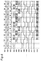
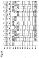
- Fig. 8 shows a first timing chart representing operations of the image packet communications system in the third embodiment. The operations of the system diagrammed in Fig. 7 are now described in detail with reference to Fig. 8.
- reference numeral 801 denotes frame signals (hereinafter, referred to as reference frame signals) generated by the buffer controller 703 based on the reference signal REF.
- the reference frame signals 801 can be readily generated by circuitry employing PLL and a composite sync vertical retrace interval detection circuit.
- the symbols A1 to A11 are designated for the frame periods of the frame signals 801.
- Reference numeral 802 denotes input image signals applied to the buffer group 702.
- Reference numeral 803 denotes transmission standard frame signals FLM1 which is generated by the transmission standard signal generator 103, using a counter, based on a clock synchronized with the high-speed packet network 110, where the network-synchronized clock is generated by the transmission image clock generator 102.
- the labels B1 to B9 denotes the frame periods of the transmission standard frame signals 803.
- the state indicated in Fig. 8 represents a case where the period of the transmission standard signal 803 is longer than that of the reference frame signal 801.
- Reference numeral 804 denotes the write and read states for the first frame memory, 805 the write and read states for the second frame memory, and 806 the write and read states for the third frame memory, where the read states are indicated by hatching.
- Reference numeral 807 denotes the write enable signal W1 for the first frame memory
- 808 denotes the read enable signal R1 for the first frame memory
- 809 the write enable signal W2 for the second frame memory
- 810 the read enable signal R2 for the second frame memory
- 811 the write enable signal W3 for the third frame memory
- 812 the read enable signal for the third frame memory.
- the enable state in all of these enabling signals is the low level.
- Reference numeral 813 represents image signals read out from the buffer group 702.
- the input image signals 802 are written to the frame memories, sequentially from the first to the third frame memories, by the write enable signals W1, W2, and W3 generated with reference to the reference frame signals 801. Meanwhile, the read-outs from the frame memories are performed sequentially, from the first to the third frame memories, by the read enable signals R1, R2, and R3 that are generated with reference to the transmission standard signal FLM1 803.
- the FL7 write operation terminates at A7, and, if in the normal state, the FL8 write state is entered at A8.
- the timing at the beginning of A8 overlaps the B6 period, however, and therefore, in the timing of the beginning of A8, the FL5 readout from the second frame memory has not finished, resulting in a state that the write operation cannot be performed.
- All of the other frame memories also are in a read-wait state. Accordingly, the FL8 image packet write operation is not performed. That is, the control is effected such that the logic of all of the write enable signals (W1, W2, W3) in the period A8 becomes high (disable state).
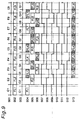
- Fig. 9 shows a second timing chart representing operations of the image packet communications system in the third embodiment shown in Fig. 7.
- items 901 are reference frame signals generated by the buffer controller 703 based on the reference signal REF, which is similar to those 801 in Fig. 8.
- the labels E1 to E9 are designated in the frame periods of the reference frame signals 901.
- Items 902 are input image signals input to the buffer group 702, as those 802 in Fig. 8.
- Items 903 are transmission standard signals generated by the transmission standard signal generator 102, as those 803 in Fig. 8.
- the labels G1 to G11 are noted in the frame periods of the transmission standard signals 903.
- the state represented in Fig. 9 represents the case where the period of the transmission standard signal 903 is shorter than that of the reference frame signal 901.
- Reference numeral 904 indicates the write and read states for the first frame memory, 905 the write and read states for the second frame memory, and 906 the write and read states for the third frame memory.
- the read states are indicated by hatching in the states 904, 905, and 906.
- Item 907 is the write enable signal W1 for the first frame memory, 908 the read enable signal R1 for the first frame memory, 909 the write enable signal W2 for the second frame memory, 910 the read enable signal R2 for the second frame memory, 911 the write enable signal W3 for the third frame memory, and 912 the read enable signal R3 for the third frame memory. All of the enable signals are in the enable state at the low level.
- Reference numeral 913 denotes the image signals read out from the buffer group 702.
- the input image signals 902 are written to the frame memories, sequentially from the first to the third frame memories, by the write enable signals W1, W2, and W3 generated with reference to the reference frame signal 901.
- Read-outs from the frame memories are made sequentially from the first to the third frame memories, by the read enable signals R1, R2, and R3 generated with reference to the transmission standard signal 903.
- the period of the transmission standard signal 903 is shorter than that of the reference frame signal 901. Therefore, there is insufficient write data, relative to the read-out speed.
- the read operation FL5 is finished in G7, and, if in the normal state, the read-out FL6 starts at the beginning time the period G8.
- the time of the start of the G8 period overlaps the end portion of the period E6, and since the write operation FL6 to the third frame memory is not finished, so the read-out is not possible.
- the other frame memories are also in a write-wait state.
- the FL5 image packet read out from the second frame memory in the period G7 is read out again in the period G8.
- the logic of the 910 signal (R2) is made low (enable state) in the G8 time, just as in the J7 time. That is, the number of image data read out is increased by reading the frame memory twice, rendering that number agreeable to the transmission standard signal 903.
- the periods of the reception standard signal and the reference frame signal are shown as radically different. In actual practice, however, the difference between the periods of the reception standard signal and the reference frame signal will be very small, with the instances of frame deletion or insertion being on the order of from once every several tens of minutes to once every several hours. At this level the disruption of image quality is almost undetectable.
- the fact that the time differential between the transmission standard signal and the reference frame signal has exceeded a certain value is detected by the fact that writing to the frame memories has become disabled, but the present invention is not limited to this method. It is also possible to detect this event by counting the number of clock beats in the frame periods of the transmission standard signals and reference frame signals.
- the third embodiment of the present invention even when the synchronization period of the high-speed packet network and the period of the reference signal differ, it is possible to build a system combining the two, while maintaining high image quality, by adjusting the image data volume.
- the fact that the time differential between the transmission standard signal and the reference signal has exceeded a certain value is detected by the fact that either writing to or reading from the frame memories has become disabled, but the present invention is not limited to this method. It is also possible to detect this event by counting the number of clock beats in the frame times of the transmission standard signals and reference signals, and adjusting the image data volume accordingly.
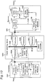
- Fig. 10 shows a schematic construction of an image packet communications system in the fourth embodiment of the present invention.
- a transmitter 1001 is fed with input image signals, where the input image signals are converted to packets (ATM cells) and the resultant ATM cell packets are sent out on an ATM network.
- the transmitter 1001 includes a transmission image clock generator 1002, transmission standard signal generator 103, and packet generator 104.
- the transmission standard signal generator 103 and packet generation means 104 are the same as those of the first embodiment shown in Fig. 1.
- the receiver is the same as the of the first embodiment shown in Fig. 1.
- Reference numeral 1003 denotes a packet switching device.
- a packet network is ordinarily comprised of one or a plurality of packet switching devices.
- the packet network is configured with a single packet switching device for brevity.
- an ATM network is used as an example of a high-speed packet network, so the packet switching device 1003 is here assumed to be an ATM switch.
- the transmitter 1001 and the receiver 105 are connected through the packet switching device 1003.
- ATM communications are assumed to have SONET standard used as the specification of the physical level. Accordingly, the packet switching device 1003 is operated synchronously with SONET frames.
- Tp1 indicates a transmission port for connecting from the transmitter 1001 to the packet switching device 1003, while Rp2 indicates a reception port connecting to the receiver 105 from the packet switching device 1003.
- ATM communications are full duplex communications, and the ports are equipped as sending and receiving ports.
- the receiving port corresponding to Tp1 and the sending port corresponding to Rp2 are not shown in Fig. 1.
- the transmission image clock generator 1002 In the transmitter 1001, the transmission image clock generator 1002 generates a transmission image clock CLK1.
- the transmission standard signal generator 103 generates a signal synchronization frame signal FLM1 based on the transmission image clock CLK1.
- the packet generator 104 generates image packets from the input image signals, based on the timing of CLK1, with reference to the frame signal FLM1 as the frame standard, and attaches image packet headers thereto, and send them out on the network from the port Tp1, using SONET frames.
- the packet switching device 1003 includes first to fourth transceiver units 1004, 1005, 1006, and 1007.
- the transceiver units are not limited to four units but may be provided in any number.
- Reference numeral 1008 denotes an internal bus provided in the packet switching device 1003 for handing data back and forth between the transceiver units.
- Reference numeral 1009 constitutes a switching device controller for controlling the transmission of data over the internal bus.
- Reference numeral 1010 constitutes a switching device standard signal generator.
- the transceiver units 1004, 1005, 1006, and 1007 perform transmissions for each port.
- the handing of data back and forth between the ports inside the packet switching device 1003 is handled by the switching device controller 1009 controlling the transmission of data via the internal bus 1008.
- the switching device standard signal generator 1010 detects SONET frames of any transceiver units and generates switching device standard signals (SFLM) subordinately synchronized to the SONET frames. Next, the switching device standard signals SFLM are distributed to each transceiver units, to thereby operate the transceiver units synchronously with the SONET frames.
- SFLM switching device standard signals
- the switching device standard signal generator 1010 have selected the first transceiver 1004 as a reference one in order to effect subordinate synchronization, so that the transceiver units 1005, 1006, and 1007 are subordinately synchronized with the switching device standard signal SFLM generated internally by the switching device standard generator.
- the transceiver units can be operated in a synchronization state with SONET frames.
- the receiver 105 is the same as that of the first embodiment shown in Fig. 1, attaining the subordinate synchronization with the signals referenced to the SONET frames input through the Rp2 port.
- the transmitter 1001, packet switching device 1003, and receiver 105 are all synchronized with reference to the SONET frames, thereby facilitating image communications where a synchronization relation is guaranteed. Accordingly, each image frame can be definitely transmitted and high image quality can be maintained in the communications.
- the means for subordinately synchronizing the terminals and switching equipment to SONET frames can be easily implemented using such as PLL circuitry.
- the internal configuration of the packet switching device in the embodiment of the present invention use buses in transferring data to and from the transceiver units, but there are various other ways in which the packet switching device can be internally configured.
- the essences of the present invention is not dependent on the internal configuration of the packet switching device. Accordingly, the scope of this invention is not exceeded by the use of some other switching method.
- the method of synchronizing the transceiver units inside the packet switching device described here employs SONET frames.
- the phase relationship of the SONET frames of the transceiver units or of the image frames is not a problem, it is permissible to implement new synchronization in the SONET frames based on a clock implemented with PLL.
- the terminals and the packet switching device are synchronized with reference to the transmitter terminal.
- the terminals and the packet switching device usually have a clock that is generated internally, and all of the devices are connected in full duplex, so it is also permissible to subordinately synchronize all of the devices to any terminal or packet switching device.
- the packet switching device is used as a single unit. In cases where a plurality of packet switching devices are used, one switching unit may be selected has the standard reference one and the other switching devices are connected so as to be subordinately synchronized thereto.
- the configuration of the fifth embodiment is the same as that of the first embodiment shown in Fig. 1.
- the transmitter terminal 101 passes cells from the ATM layer to the physical layer, the cell transmission period at the ATM layer is preserved as is and there is no reception at the receiver terminal 105.
- the cell transmission period at the ATM layer is preserved as is and there is no reception at the receiver terminal 105.
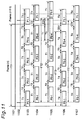
- Fig. 11 showing a timing chart for the fifth embodiment, the problems arising in image communications due to fluctuation are explained, and a method of resolving those problems is described.
- reference numeral 1101 denotes a transmission synchronizing frame signal FLM1 in the transmitter 101.
- Reference numeral 1102 denotes a reception synchronizing frame signal FLM2 inside the receiver 105.
- FLM2 was described as reversing every frame. In Fig. 11, however, in order to make a comparison with FLM1 1101, this has been rewritten as a signal that generates a pulse at the leading edge of the frame.
- Item 1103 is a transmission packet sent from the transmitter 101
- 1104 is a transmission packet received by the receiver 105 when there is no fluctuation
- 1105 is a transmission packet received by the receiver 105 when there is fluctuation.
- Reference numeral 1106 denotes a transmission packet sent from the transmitter 101 according to the fifth embodiment of the present invention
- 1107 denotes a transmission packet received by the receiver 105 when there is fluctuation, according to the fifth embodiment of the present invention.
- one frame of image signals is sent in four transmission packets, but the invention is not limited thereto.
- the transmission packet 1103 four transmission packets are sent, each with a period of T1, and with the interval between two adjacent transmission packets being T2.
- the transmission packet 1104 data pieces are received at the same intervals as those of the transmission packet 1103. Accordingly, image quality is guaranteed because image data are normally received in one frame interval.
- the data transmission timing at the transmitter is made such that the sending of the transmission packet is concluded within a time period (FT3) that is obtained by subtracting the CDV value from one frame period (FT1), represented as follows.
- FT3 FT1 - CDV
- each of the transmission packets is sent within the time interval T4, with an interval T5 separating the adjacent two transmission packets one from another.
- Reference numeral 1107 represents the reception timing at the receiver 105 when the transmission packets are sent based on the timing 1106 from the transmitter with occurrence of fluctuation.
- fluctuation is represented as occurring in P0-4, similar to the case 1105.
- the actual configuration of the fifth embodiment can be easily implemented by providing a counter for counting the frame periods inside the packet generator 104 in Fig. 1, and transmitting the transmission packets with the transmission timing described above.
- an image packet communications system can be provided which maintains high image quality, with no destruction of images even when fluctuation occurs on the high-speed packet network.
- the delay fluctuations are not something that the transmission packets mutually influence, and therefore, it is only necessary to consider the transmission time for the leading cell in the transmission packet at the head of each frame and the final cell in the final transmission packet.
- the essential point of the present invention is in transmitting the transmission packets contained in one frame period within a period that is obtained by subtracting the value of the maximum delay fluctuation from one frame period value.
- the number of transmission packets may be set at any number (although, in this embodiment, the number of transmission packets is set at 4) without exceeding the scope of the present invention.
- the transmission times for the transmission packets are here made the same, as are the intervals between the transmission packets, but these may be set at any value without exceeding the scope of the present invention.
- the value subtracted from one frame time may be any value whatever so long as it is equal to or greater than the value of the maximum delay fluctuation.
- the example described is one in which the sending timing is controlled at the transmission packet processing layer, but the scope of the present invention will not be exceeded even though the sending timing be controlled at another layer such as the ATM layer.
- a packet switching system is taken as the example in the descriptions.
- the invention is not limited to packet switching systems, but is of course effective for use in line switching systems and local area networks (LANs), for example.
- LANs local area networks
- the present invention as described in the foregoing, provides the following remarkable effects.
- transmissions are conducted with a clock subordinately synchronized to the network clock and frame signals generated based on the clock established as the synchronization standard at the transmitter terminal, and in the meanwhile, transmissions are conducted with a clock subordinately synchronized to the network clock and frame signals generated based on the clock established as the synchronization standard at the receiving-end terminal, thus affording the benefit of being able to build a communications system where the synchronization between the transmitter end and the receiver and can be guaranteed.
- the image packets are transmitted after attaching image packet headers thereto, wherefore, even when a packet loss or error occurs in the network, and a transmission packet is lost, that transmission packet error has no effect on the other transmission packets, and normally received transmission packets are securely received and output. Accordingly, an effect is afforded in that high image quality can be maintained in the transmissions even when packet losses or errors occur.
- the synchronization period of the network clock in the high-speed packet network differs from the period of the reference signal at the receiver side, it is possible to adjust the image data volume so that the image data received from the network are made suitable to the reference signal period. Accordingly, it is possible to build systems wherein equipment synchronized to the network clock is connected to equipment synchronized to the reference signal, thereby affording the effect of being able to guarantee frame synchronization for all equipment in the system.
- the volume of image data can be adjusted so that the image data input synchronized to the reference signal are made suitable to the period of the network clock.
- This makes it possible to interconnect equipment synchronized to the reference signal and equipment synchronized to the network clock, thus affording the effect of being able to guarantee the frame synchronization of all equipment in the system.
- the image data volume is adjusted in frame units, so that high image quality can be preserved.
- an image packet communications system assuring the frame synchronization of all equipment included in the transmitter, the high-speed packet network, and the receiver, thereby affording the effect of maintaining high image quality.
- the image data in each frame are transmitted without fail within the frame period, even when fluctuations occur in the high-speed packet network, thereby affording the effect of realizing an image packet communications system assuring high image quality.
- the first, second, third, fourth, and fifth aspects of the present invention all afford the benefit of being realizable in a simple configuration. Furthermore, the present invention can be implemented without detecting any kind of signal from the data, thus providing the benefit of being applicable irrespective of the data being communicated.
Landscapes
- Engineering & Computer Science (AREA)
- Computer Networks & Wireless Communication (AREA)
- Signal Processing (AREA)
- Data Exchanges In Wide-Area Networks (AREA)
- Television Systems (AREA)
- Two-Way Televisions, Distribution Of Moving Picture Or The Like (AREA)
Applications Claiming Priority (2)
| Application Number | Priority Date | Filing Date | Title |
|---|---|---|---|
| JP27412297 | 1997-10-07 | ||
| JP9274122A JPH11112938A (ja) | 1997-10-07 | 1997-10-07 | 画像パケット通信システム |
Publications (3)
| Publication Number | Publication Date |
|---|---|
| EP0921703A2 true EP0921703A2 (de) | 1999-06-09 |
| EP0921703A3 EP0921703A3 (de) | 1999-07-28 |
| EP0921703B1 EP0921703B1 (de) | 2004-07-28 |
Family
ID=17537335
Family Applications (1)
| Application Number | Title | Priority Date | Filing Date |
|---|---|---|---|
| EP98118885A Expired - Lifetime EP0921703B1 (de) | 1997-10-07 | 1998-10-06 | Bild-Paketkommunikationssystem |
Country Status (5)
| Country | Link |
|---|---|
| US (1) | US6438143B1 (de) |
| EP (1) | EP0921703B1 (de) |
| JP (1) | JPH11112938A (de) |
| CN (1) | CN1182676C (de) |
| DE (1) | DE69825241T2 (de) |
Cited By (1)
| Publication number | Priority date | Publication date | Assignee | Title |
|---|---|---|---|---|
| EP1691497A3 (de) * | 2005-02-14 | 2011-03-23 | Fujitsu Limited | Verfahren und Vorrichtung zm Senden der terrestrischen digitalen Rundfunksignale |
Families Citing this family (9)
| Publication number | Priority date | Publication date | Assignee | Title |
|---|---|---|---|---|
| US6647428B1 (en) * | 2000-05-05 | 2003-11-11 | Luminous Networks, Inc. | Architecture for transport of multiple services in connectionless packet-based communication networks |
| US7535888B1 (en) * | 2000-05-26 | 2009-05-19 | Bigband Networks, Inc. | System and method for providing in-band timing information to digital home communication terminals |
| US6990097B2 (en) * | 2001-06-01 | 2006-01-24 | 4198638 Canada Inc. | Cell-based switch fabric with inter-cell control for regulating packet flow |
| US6990096B2 (en) * | 2001-06-01 | 2006-01-24 | 4198638 Canada Inc. | Cell-based switch fabric architecture implemented on a single chip |
| EP1715612B1 (de) * | 2004-09-09 | 2011-08-10 | Panasonic Corporation | Sende vorrichtung, weiterleitungsvorrichtung, empfäangervorrichtung und netzwerksystem mit diesen vorrichtungen |
| US20080181832A1 (en) * | 2007-01-30 | 2008-07-31 | Lih-Ren Shiue | Pocket-size ozone generator |
| JP5625290B2 (ja) * | 2009-09-09 | 2014-11-19 | 富士通株式会社 | 信号処理回路、インタフェースユニット、フレーム伝送装置及びセグメントデータの読み出し方法 |
| JP5874178B2 (ja) * | 2010-04-09 | 2016-03-02 | ソニー株式会社 | カメラシステム、カメラ装置、カメラ制御装置、および中継装置 |
| CN104205852A (zh) * | 2012-04-13 | 2014-12-10 | 索尼公司 | 信息处理装置和方法以及程序 |
Family Cites Families (8)
| Publication number | Priority date | Publication date | Assignee | Title |
|---|---|---|---|---|
| JP2809524B2 (ja) | 1991-05-10 | 1998-10-08 | 沖電気工業株式会社 | デジタル伝送システムの同期方式 |
| JPH0514399A (ja) | 1991-07-03 | 1993-01-22 | Oki Electric Ind Co Ltd | 画像パケツト通信システム |
| JPH0514763A (ja) | 1991-07-03 | 1993-01-22 | Oki Electric Ind Co Ltd | 画像パケツト通信システム |
| US5287182A (en) * | 1992-07-02 | 1994-02-15 | At&T Bell Laboratories | Timing recovery for variable bit-rate video on asynchronous transfer mode (ATM) networks |
| GB2293292B (en) * | 1994-09-14 | 1998-12-02 | Northern Telecom Ltd | Hybrid cross connect |
| US6307868B1 (en) * | 1995-08-25 | 2001-10-23 | Terayon Communication Systems, Inc. | Apparatus and method for SCDMA digital data transmission using orthogonal codes and a head end modem with no tracking loops |
| US5936968A (en) * | 1997-05-28 | 1999-08-10 | Sarnoff Corporation | Method and apparatus for multiplexing complete MPEG transport streams from multiple sources using a PLL coupled to both the PCR and the transport encoder clock |
| US6243369B1 (en) * | 1998-05-06 | 2001-06-05 | Terayon Communication Systems, Inc. | Apparatus and method for synchronizing an SCDMA upstream or any other type upstream to an MCNS downstream or any other type downstream with a different clock rate than the upstream |
-
1997
- 1997-10-07 JP JP9274122A patent/JPH11112938A/ja active Pending
-
1998
- 1998-10-06 DE DE69825241T patent/DE69825241T2/de not_active Expired - Fee Related
- 1998-10-06 EP EP98118885A patent/EP0921703B1/de not_active Expired - Lifetime
- 1998-10-07 US US09/167,496 patent/US6438143B1/en not_active Expired - Fee Related
- 1998-10-07 CN CNB98120127XA patent/CN1182676C/zh not_active Expired - Fee Related
Cited By (1)
| Publication number | Priority date | Publication date | Assignee | Title |
|---|---|---|---|---|
| EP1691497A3 (de) * | 2005-02-14 | 2011-03-23 | Fujitsu Limited | Verfahren und Vorrichtung zm Senden der terrestrischen digitalen Rundfunksignale |
Also Published As
| Publication number | Publication date |
|---|---|
| DE69825241D1 (de) | 2004-09-02 |
| CN1182676C (zh) | 2004-12-29 |
| JPH11112938A (ja) | 1999-04-23 |
| US6438143B1 (en) | 2002-08-20 |
| EP0921703B1 (de) | 2004-07-28 |
| DE69825241T2 (de) | 2005-07-28 |
| CN1215270A (zh) | 1999-04-28 |
| EP0921703A3 (de) | 1999-07-28 |
Similar Documents
| Publication | Publication Date | Title |
|---|---|---|
| US9025467B2 (en) | Hitless protection for traffic received from 1+1 protecting line cards in high-speed switching systems | |
| US6345052B1 (en) | Method and apparatus for the reliable transition of status signals from an interface device when using a localized sampling architecture | |
| TW457820B (en) | Determining time slot delay for ATM transmission | |
| EP0921703B1 (de) | Bild-Paketkommunikationssystem | |
| WO1997003508A1 (en) | Data transmission method, data transmission apparatus and data transmission system | |
| CN1051187C (zh) | 同步数字系列数据传输系统 | |
| JPH04220829A (ja) | セル位相乗換回路 | |
| US6757304B1 (en) | Method and apparatus for data communication and storage wherein a IEEE1394/firewire clock is synchronized to an ATM network clock | |
| US6532243B1 (en) | Virtual time loop | |
| JP2002354027A (ja) | リアセンブリ手段、サーキットエミュレーションサービス装置及びatm同期制御方法 | |
| US6418144B1 (en) | AAL terminal system of duplex configuration and synchronization method | |
| US6292487B1 (en) | Data transmission system and method | |
| US5859850A (en) | Elastic store circuit for composite cells switched through an ATM network | |
| US6928080B2 (en) | Transporting variable length ATM AAL CPS packets over a non-ATM-specific bus | |
| JP2576811B2 (ja) | セル送出制御方式 | |
| JP3076456B2 (ja) | 同期制御方式 | |
| JP3055530B2 (ja) | Atmをstmデータに変換するaal1終端装置の2重化方法及びその構成 | |
| JP3372075B2 (ja) | 同期制御方式 | |
| KR0175571B1 (ko) | 순방향 성능감시 운용 및 유지보수 셀 생성방법 | |
| JP2947687B2 (ja) | バッファ装置 | |
| KR0173210B1 (ko) | 광대역 종합정보통신망 단말 어댑터에서의 가변비트율 데이타와 고정비트율 데이타를 동시에 처리하는 전송장치 및 그 방법 | |
| JP3570967B2 (ja) | 2重化aal1変換装置及びそれに用いる同期化方法 | |
| JP2000324072A (ja) | ポインタ終端部と無瞬断切替方式 | |
| KR0132956B1 (ko) | 비동기 전달모드 망 정합 회로팩 | |
| Fujikawa et al. | Experimental considerations on adaptive clock method for transmitting microprocessor-based current differential teleprotection signals in ATM networks |
Legal Events
| Date | Code | Title | Description |
|---|---|---|---|
| PUAI | Public reference made under article 153(3) epc to a published international application that has entered the european phase |
Free format text: ORIGINAL CODE: 0009012 |
|
| 17P | Request for examination filed |
Effective date: 19981030 |
|
| AK | Designated contracting states |
Kind code of ref document: A2 Designated state(s): DE FR GB |
|
| AX | Request for extension of the european patent |
Free format text: AL;LT;LV;MK;RO;SI |
|
| PUAL | Search report despatched |
Free format text: ORIGINAL CODE: 0009013 |
|
| AK | Designated contracting states |
Kind code of ref document: A3 Designated state(s): AT BE CH CY DE DK ES FI FR GB GR IE IT LI LU MC NL PT SE |
|
| AX | Request for extension of the european patent |
Free format text: AL;LT;LV;MK;RO;SI |
|
| AKX | Designation fees paid |
Free format text: DE FR GB |
|
| 17Q | First examination report despatched |
Effective date: 20030527 |
|
| GRAP | Despatch of communication of intention to grant a patent |
Free format text: ORIGINAL CODE: EPIDOSNIGR1 |
|
| GRAS | Grant fee paid |
Free format text: ORIGINAL CODE: EPIDOSNIGR3 |
|
| GRAA | (expected) grant |
Free format text: ORIGINAL CODE: 0009210 |
|
| AK | Designated contracting states |
Kind code of ref document: B1 Designated state(s): DE FR GB |
|
| REG | Reference to a national code |
Ref country code: GB Ref legal event code: FG4D |
|
| REF | Corresponds to: |
Ref document number: 69825241 Country of ref document: DE Date of ref document: 20040902 Kind code of ref document: P |
|
| ET | Fr: translation filed | ||
| PLBE | No opposition filed within time limit |
Free format text: ORIGINAL CODE: 0009261 |
|
| STAA | Information on the status of an ep patent application or granted ep patent |
Free format text: STATUS: NO OPPOSITION FILED WITHIN TIME LIMIT |
|
| 26N | No opposition filed |
Effective date: 20050429 |
|
| PGFP | Annual fee paid to national office [announced via postgrant information from national office to epo] |
Ref country code: DE Payment date: 20081014 Year of fee payment: 11 |
|
| PG25 | Lapsed in a contracting state [announced via postgrant information from national office to epo] |
Ref country code: DE Free format text: LAPSE BECAUSE OF NON-PAYMENT OF DUE FEES Effective date: 20100501 |
|
| PGFP | Annual fee paid to national office [announced via postgrant information from national office to epo] |
Ref country code: FR Payment date: 20101020 Year of fee payment: 13 |
|
| PGFP | Annual fee paid to national office [announced via postgrant information from national office to epo] |
Ref country code: GB Payment date: 20101006 Year of fee payment: 13 |
|
| GBPC | Gb: european patent ceased through non-payment of renewal fee |
Effective date: 20111006 |
|
| REG | Reference to a national code |
Ref country code: FR Ref legal event code: ST Effective date: 20120629 |
|
| PG25 | Lapsed in a contracting state [announced via postgrant information from national office to epo] |
Ref country code: GB Free format text: LAPSE BECAUSE OF NON-PAYMENT OF DUE FEES Effective date: 20111006 Ref country code: FR Free format text: LAPSE BECAUSE OF NON-PAYMENT OF DUE FEES Effective date: 20111102 |