EP0921834B1 - Commande de position de gaine de catheter endoscopique - Google Patents
Commande de position de gaine de catheter endoscopique Download PDFInfo
- Publication number
- EP0921834B1 EP0921834B1 EP97934101A EP97934101A EP0921834B1 EP 0921834 B1 EP0921834 B1 EP 0921834B1 EP 97934101 A EP97934101 A EP 97934101A EP 97934101 A EP97934101 A EP 97934101A EP 0921834 B1 EP0921834 B1 EP 0921834B1
- Authority
- EP
- European Patent Office
- Prior art keywords
- distal end
- sheath
- needle
- catheter
- connector
- Prior art date
- Legal status (The legal status is an assumption and is not a legal conclusion. Google has not performed a legal analysis and makes no representation as to the accuracy of the status listed.)
- Expired - Lifetime
Links
Images


Classifications
-
- A—HUMAN NECESSITIES
- A61—MEDICAL OR VETERINARY SCIENCE; HYGIENE
- A61B—DIAGNOSIS; SURGERY; IDENTIFICATION
- A61B17/00—Surgical instruments, devices or methods
- A61B17/34—Trocars; Puncturing needles
- A61B17/3478—Endoscopic needles, e.g. for infusion
-
- A—HUMAN NECESSITIES
- A61—MEDICAL OR VETERINARY SCIENCE; HYGIENE
- A61M—DEVICES FOR INTRODUCING MEDIA INTO, OR ONTO, THE BODY; DEVICES FOR TRANSDUCING BODY MEDIA OR FOR TAKING MEDIA FROM THE BODY; DEVICES FOR PRODUCING OR ENDING SLEEP OR STUPOR
- A61M25/00—Catheters; Hollow probes
- A61M25/01—Introducing, guiding, advancing, emplacing or holding catheters
- A61M25/06—Body-piercing guide needles or the like
-
- A—HUMAN NECESSITIES
- A61—MEDICAL OR VETERINARY SCIENCE; HYGIENE
- A61M—DEVICES FOR INTRODUCING MEDIA INTO, OR ONTO, THE BODY; DEVICES FOR TRANSDUCING BODY MEDIA OR FOR TAKING MEDIA FROM THE BODY; DEVICES FOR PRODUCING OR ENDING SLEEP OR STUPOR
- A61M5/00—Devices for bringing media into the body in a subcutaneous, intra-vascular or intramuscular way; Accessories therefor, e.g. filling or cleaning devices, arm-rests
- A61M5/178—Syringes
- A61M5/31—Details
- A61M5/32—Needles; Details of needles pertaining to their connection with syringe or hub; Accessories for bringing the needle into, or holding the needle on, the body; Devices for protection of needles
- A61M5/3205—Apparatus for removing or disposing of used needles or syringes, e.g. containers; Means for protection against accidental injuries from used needles
- A61M5/321—Means for protection against accidental injuries by used needles
- A61M5/3243—Means for protection against accidental injuries by used needles being axially-extensible, e.g. protective sleeves coaxially slidable on the syringe barrel
-
- A—HUMAN NECESSITIES
- A61—MEDICAL OR VETERINARY SCIENCE; HYGIENE
- A61B—DIAGNOSIS; SURGERY; IDENTIFICATION
- A61B90/00—Instruments, implements or accessories specially adapted for surgery or diagnosis and not covered by any of the groups A61B1/00 - A61B50/00, e.g. for luxation treatment or for protecting wound edges
- A61B90/08—Accessories or related features not otherwise provided for
- A61B2090/0801—Prevention of accidental cutting or pricking
-
- A—HUMAN NECESSITIES
- A61—MEDICAL OR VETERINARY SCIENCE; HYGIENE
- A61M—DEVICES FOR INTRODUCING MEDIA INTO, OR ONTO, THE BODY; DEVICES FOR TRANSDUCING BODY MEDIA OR FOR TAKING MEDIA FROM THE BODY; DEVICES FOR PRODUCING OR ENDING SLEEP OR STUPOR
- A61M5/00—Devices for bringing media into the body in a subcutaneous, intra-vascular or intramuscular way; Accessories therefor, e.g. filling or cleaning devices, arm-rests
- A61M5/178—Syringes
- A61M5/31—Details
- A61M5/32—Needles; Details of needles pertaining to their connection with syringe or hub; Accessories for bringing the needle into, or holding the needle on, the body; Devices for protection of needles
- A61M5/3205—Apparatus for removing or disposing of used needles or syringes, e.g. containers; Means for protection against accidental injuries from used needles
- A61M5/321—Means for protection against accidental injuries by used needles
- A61M5/3243—Means for protection against accidental injuries by used needles being axially-extensible, e.g. protective sleeves coaxially slidable on the syringe barrel
- A61M5/3245—Constructional features thereof, e.g. to improve manipulation or functioning
- A61M2005/3246—Constructional features thereof, e.g. to improve manipulation or functioning being squeezably deformable for locking or unlocking purposes, e.g. with elliptical cross-section
-
- A—HUMAN NECESSITIES
- A61—MEDICAL OR VETERINARY SCIENCE; HYGIENE
- A61M—DEVICES FOR INTRODUCING MEDIA INTO, OR ONTO, THE BODY; DEVICES FOR TRANSDUCING BODY MEDIA OR FOR TAKING MEDIA FROM THE BODY; DEVICES FOR PRODUCING OR ENDING SLEEP OR STUPOR
- A61M25/00—Catheters; Hollow probes
- A61M25/0021—Catheters; Hollow probes characterised by the form of the tubing
- A61M25/0023—Catheters; Hollow probes characterised by the form of the tubing by the form of the lumen, e.g. cross-section, variable diameter
-
- A—HUMAN NECESSITIES
- A61—MEDICAL OR VETERINARY SCIENCE; HYGIENE
- A61M—DEVICES FOR INTRODUCING MEDIA INTO, OR ONTO, THE BODY; DEVICES FOR TRANSDUCING BODY MEDIA OR FOR TAKING MEDIA FROM THE BODY; DEVICES FOR PRODUCING OR ENDING SLEEP OR STUPOR
- A61M25/00—Catheters; Hollow probes
- A61M25/01—Introducing, guiding, advancing, emplacing or holding catheters
- A61M25/06—Body-piercing guide needles or the like
- A61M25/0612—Devices for protecting the needle; Devices to help insertion of the needle, e.g. wings or holders
- A61M25/0631—Devices for protecting the needle; Devices to help insertion of the needle, e.g. wings or holders having means for fully covering the needle after its withdrawal, e.g. needle being withdrawn inside the handle or a cover being advanced over the needle
Definitions
- This invention relates to endoscopic catheters, and more particularly relates to catheters equipped to accomplish a therapeutic procedure at an internal site such as a gastrointestinal site.
- Endoscopic catheters are employed for accomplishing a variety of internal therapeutic procedures, for example, for enabling injection therapy at a site of bleeding in the digestive system.
- a catheter equipped for such injection therapy includes a needle at the distal end of an injection sheath through which liquid therapeutic injection media is channeled to the needle.
- An outer sheath over the injection sheath is also typically included to provide both a passageway for irrigation fluid around the needle and a protective encasement for the needle as the distal end of the catheter is moved to the therapy site.
- Endoscopic catheters equipped for other applications e.g., delivery of a mechanical vasoconstrictor to an internal site, similarly generally include a mechanical feature at the distal end of an inner sheath that is encased in an outer sheath.
- an inner catheter sheath and its distal end element e.g., a needle
- the position of the distal end of an inner catheter sheath and its distal end element is controlled with respect to the outer catheter sheath by way of a remote hand-operable control mechanism at the catheter proximal end opposite the distal end element.
- a remote hand-operable control mechanism at the catheter proximal end opposite the distal end element.
- EP-A1-0409057 discloses an injection device having a main body holding a needle and a needle-protection element.
- the needle protection element can be moved from its stand-by position towards the needle tip to a protective position. In the protective position, the needle protection element completely surrounds the needle tip.
- the needle protection element includes a projection engaged onto a groove having two end recesses formed in the outer surface of the main body.
- US-A-5380292 discloses an adjustable needle mechanism for gastrointestinal use, in combination with an endoscope.
- the needle is received within a catheter or sheath and is moveable between a first position in which it projects out of the catheter and a second position in which it is withdrawn into the catheter.
- a rotatable knob is provided to adjust the extent of projection of the needle when it is in the first position thereby eliminating any necessity to trim the end of the catheter.
- the invention provides an endoscopic catheter position control that enables precise control of distal catheter sheath ends relative to each other while accommodating the long length and flexibility of typical catheters and proximal, remote hand-operable control mechanisms.
- the invention provides a catheter assembly comprising:
- irrigation or other fluid can be delivered through the outer sheath in the conventional manner with the inner interconnector and distal end member in a fully-retracted position.
- Unobstruction of the outer sheath fluid communication path provides a superior advantage in that it does not require the addition of an auxiliary or additional fluid communication path beyond the conventional path.
- the end position controller is located at a relatively distal position along the tubular sheath and is embodied as at least one indentation in the sheath that has an inner diameter that is less than an outer diameter of the interconnector at least one point along the interconnector.
- the interconnector can include a connector that has an outer diameter that is greater than the inner diameter of the indentation.
- the connector enables connection of the distal end member to the interconnector.
- a plurality of indentations are provided in the sheath, with each indentation being circumferentially separated from adjacent indentations by a flow channel.
- the tubular sheath is a polytetrafluoroethylene sheath and further, the interconnector is a flexible tubular inner sheath.
- the end member can be embodied as a needle cannula connected to the inner sheath, with a connector connecting the needle cannula to the inner sheath.
- the distal end member comprises a needle cannula internal to the sheath and having a distal tip, the needle cannula tip being reciprocally axially movable relative the sheath distal end between a retracted position proximal of the sheath distal end whereby the sheath covers the needle tip and an extended position whereby the needle tip protrudes beyond the sheath distal end; and the elongated member comprises an elongated flexible tube internal to the sheath and having a distal end and a proximal end, the tube distal end being connected to the needle cannula by the connector and the tube proximal end being connected to the position actuator for axially reciprocating the needle tip relative to the sheath distal end.
- the tubular sheath and the flexible tube each provide a continuous fluid transmission path between the corresponding sheath and tube distal and proximal ends.
- the end position controller is in one embodiment located at a relatively distal position along the sheath, preferably corresponding to a fully-retracted needle tip position.
- the invention provides a syringe comprising the assembly of the present invention wherein the tubular sheath comprises a barrel having a distal end and a proximal end; the distal end member comprises a needle cannula having a distal tip, the needle cannula tip being located internal to the barrel and being reciprocally axially movable relative to the barrel distal end between a retracted position proximal of the barrel distal end whereby the barrel covers the needle tip and an extended position whereby the needle tip protrudes beyond the barrel distal end; the elongated member comprises a needle plunger rod internal to the barrel and having a distal end and a proximal end, the rod distal end being connected to the needle cannula via the connector and the rod proximal end being connected to the position actuator for axially reciprocating the needle tip relative to the barrel distal end; and the location of the distal end position controller corresponds to a fully retracted needle tip position.
- the position control of the invention facilitates effective and reliable hand-operable remote control of catheter and syringe distal end members with a mechanism that can be located locally to the distal end but that does not itself require external control; i.e. it provides automatic position control.
- This control can be applied to a wide range of catheter and syringe configurations where only remote active control of distal end elements can be relied upon during a therapeutic procedure.
- FIG. 1 there is shown an example endoscopic catheter 10 for which the position control of the invention enables effective control of the relative positions of inner and outer catheter sheaths.
- the catheter 10 is shown inserted into an internal cavity through an endoscope 14.
- the endoscope is of a conventional configuration and includes a flexible hollow tube 16 for advancement through an internal cavity 12.
- the catheter 10 includes an outer sheath 18 and generally coaxial inner sheath (not shown), which are together advanced through the internal cavity through the endoscope hollow tube.
- the inner sheath is equipped with a distal end mechanism, such as a needle 20, that can be advanced forwardly beyond the distal end of the outer sheath 18 for therapeutically treating an internal site 22 along the cavity.
- End mechanisms other than needles e.g., forceps. equipped on either or both the outer or inner catheter sheaths, can also be employed, as will be readily recognized.
- the endoscope tube and catheter outer and inner sheaths are formed of a flexible, durable material such as medical grade polytetrafluoroethylene (PTFE).
- PTFE medical grade polytetrafluoroethylene
- the PTFE tubing can be easily advanced around curves in internal cavities and is substantially impervious to and compatible with both therapeutic and bodily fluids.
- the PTFE tube and sheaths are at least about two meters in length, whereby even relatively deep internal sites can be reached.
- the catheter 10 includes a hand control 24 including, e.g., a thumb ring 26 and finger grips 28 that cooperate to enable manual control of the distal ends of the catheter sheaths as the catheter is advanced through the endoscope in the internal cavity.
- a hand control 24 including, e.g., a thumb ring 26 and finger grips 28 that cooperate to enable manual control of the distal ends of the catheter sheaths as the catheter is advanced through the endoscope in the internal cavity.
- the thumb ring 26 is first fully retracted from the finger grips 28; this retracted handle position corresponds to full retraction of the catheter inner sheath and its distal end member, e.g., a needle, into the catheter outer sheath.
- the catheter is then advanced through the endoscope to the intended internal site, optimally with the catheter needle remaining fully retracted.
- irrigation of the site is then typically accomplished by way of the outer sheath; here, an irrigation port 30 in the hand control 24 is employed to introduce, e.g., a flushing fluid to the internal site prior to the start of a therapeutic procedure.
- the needle or other distal end member on the inner catheter sheath is maintained in a fully- or at least partially-retracted position during this irrigation.
- the irrigation fluid thereby flows around the inner sheath and needle in the outer sheath as it is delivered to the site.
- the needle or other distal end member is then actuated or deployed to accomplish a procedure such as injection therapy at the intended site.
- This deployment is enabled by actuating the thumb ring 26 toward the finger grips 28, whereby the tip of the needle is positioned beyond the distal end of the catheter outer sheath, as shown in the figure.
- the injection agent can be delivered to the needle through the inner sheath by way of an injection port 32 in the hand control 24.
- the dual, isolated irrigation-injection fluid communication with the internal site is commonly required to effectively accomplish a desired therapy, and is well-enabled by the generally coaxial dual sheath configuration of the catheter, in combination with needle deployment control.
- the needle or other distal end member of the catheter inner sheath is fully retracted into the outer sheath by fully actuating the thumb mechanism away from the finger grips in the hand control.
- the distal end of the catheter can then be moved to other internal sites for additional therapeutic procedures, or can be fully withdrawn from the endoscope.
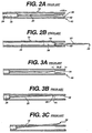
- Figs. 2A and 2B there are shown cross-sections of the catheter with a catheter needle distal end member shown in optimal retracted and extended positions, respectively.
- the catheter inner sheath 34 is explicitly shown connected to the needle 20 by way of a connector, e.g., a crimp ring 36.
- the tip 38 of the needle is preferably retracted into the outer sheath 18 by an a priori retraction distance, R.
- the retraction distance, R is preferably sufficient to ensure that the needle tip cannot be exposed as the distal end of the catheter is forwardly advanced through an internal cavity.
- irrigation or other fluid introduced to the proximal end of the outer sheath flows through the outer sheath and axially around the inner sheath 34, crimp ring 36, and needle 20 to be delivered at the distal end 40 of the outer sheath.
- the catheter outer sheath includes a distal end guard 42 secured at the distal end 40 of the outer sheath.
- a guard is typically formed of, e.g., a length of stainless steel tubing that is swaged inside the outer sheath.
- the distal end guard 42 This extension is limited by the distal end guard 42; the inner diameter of the guard is less than the outer diameter of the crimp ring 36, whereby the crimp ring forward travel is stopped at the rear end 44 of the distal end guard 42.
- the intended therapeutic procedure can be accomplished, after which the needle is preferably retracted to its protected position as shown in Fig. 2A.
- the end guard ensures that the needle or other catheter distal end member does not extend beyond an a priori safe distance corresponding to the given procedure.
- the inner and outer catheter sheaths are typically positioned with the inner sheath and distal end member, such as a needle, in a retracted position and are sterilized by way of a heating process, during which the sheaths expand and then later contract during cooling.
- the catheter is commonly shipped and stored prior to use in a coiled configuration. Due to the occurrence of friction, differential expansion, contraction, and axial movement of the two catheter sheaths during these processes and configurations, the distal end of the inner sheath may not be located in an expected axial position with respect to the outer sheath.
- the tip 30 of a forward end needle might be retracted from the distal end 40 of the outer sheath by a distance greater than the intended retraction distance, R , instead being retracted an additional error distance, E .
- the unpredictable friction between the inner and outer sheaths as the catheter is advanced through an endoscope also contribute to the error distance.
- the stretchable, flexible nature of the PTFE sheaths inherently results in unpredictable relative movement of the two sheaths as the outer sheath brushes against the endoscope tube while being advanced through the tube along curves in an internal cavity; commonly, very tight inner cavity angles must be navigated.
- the needle tip 38 can actually pierce the outer sheath 38, thereby extending beyond the catheter.
- the endoscope tube can also be pierced and/or serious trauma can occur as the catheter is advanced through the endoscope along an internal cavity; as mentioned earlier, internal cavities often present quite tight angles, thereby exaggerating the potential for this to occur.
- the potential for occurrence of this over-retraction condition is a serious concern for and limitation of typical catheters.
- the sheath position control 50 includes one or more geometric features, at one or more locations along the catheter, that limit the retraction range of the inner catheter sheath and its distal end member while accommodating the dual fluid communication channels provided by the inner and outer sheaths.
- the outer sheath 18 is provided with one or more limited indentations 54 that result in a discontinuous radial profile of the outer sheath at the location of the one or more indentations.
- the inner diameter of each such indentation is less than the outer diameter of one or more features on the inner sheath, e.g., the crimp ring securing the needle to the inner sheath.
- the indentations limit retraction of the rear face 52 of the crimp ring 36 to only the location of the indentations.
- the one or more indentations be located along the outer sheath at a point or points such that full retraction of the catheter hand control and corresponding retraction of the crimp ring, or other inner sheath feature, to the indentations results in a desired a priori retraction distance, R , of the needle tip 38 from the distal end 40 of the outer sheath, with R , preferably corresponding to a fully-retracted needle tip, i.e., needle tip that is safely within the outer sheath.
- the indentation location correspond to a retraction distance, R, that is less than the extent of the proximal end 44 of the distal end guard 42.
- the sheath position control indentations 54 are not continuous around the circumference of the outer sheath. Adjacent each indentation are flow channels 56. These channels are each preferably of at least a minimum cross-sectional area that allows fluid to flow through the channel. Irrigation or other fluid can then be delivered through the outer sheath in the conventional manner with the inner sheath and needle or other distal end member in a fully-retracted position. Fluid can thus pass freely around the inner sheath with minimal resistance. Unobstruction of the outer sheath fluid communication path provides a superior advantage in that it does not require the addition of an auxiliary or additional fluid communication path beyond the conventional path.
- Fig. 4B While four sheath position control indentations 54 are shown in Fig. 4B, it is to be recognized that any reasonable number could be employed, depending on a given catheter design application and requirement.
- the use of such indentations is particularly advantageous in that the indentations can be very easily manufactured.
- a conventional crimping tool can be used to apply the desired number of indentations at an intended location or locations, without the need for additional materials or separate parts.
- the resulting indentations retain the flexibility of the outer sheath such that the catheter retains its ability to be advanced through tightly-curved interior cavities.
- This crimping technique is based on the use of a sheath material that can retain a crimp indentation once it is impressed on the sheath, and thus such a material, e.g., PTFE, is preferred for the outer sheath.
- a sheath material that can retain a crimp indentation once it is impressed on the sheath, and thus such a material, e.g., PTFE, is preferred for the outer sheath.
- the sheath position control of the invention can be embodied in other manners, however.
- a sleeve, band, ligature, or ring can be placed externally around the outer sheath at a desired location or locations to impress and maintain one or more indentations in the outer sheath.
- a sleeve or ring can be secured internally to the outer sheath at a desired location to itself act as the position control feature.
- Other such position control features are contemplated by the invention.
- one or more protrusions, sleeves, bands, or rings can be placed externally around the inner sheath internal to the outer sheath at a desired location or locations to cooperate with one or more outer sheath features.
- the position control feature or features embody a nonuniform radial profile such that flow channels between the outer sheath and inner sheath are provided.
- the sheath position control 50 of the invention enables reliable , and effective forward extension of the inner sheath 34 and needle 20 all the way to the proximal end 44 of the distal end guard 42.
- the inner sheath and needle can not retract further than the position control 50, whereby full extension of the catheter hand control results in a corresponding full extension of the inner sheath and needle. If during manufacture or use the inner sheath and needle advance slightly ahead of the position control 50, the end guard 42 ensures that the needle does not extend beyond its intended range when the hand control extension is actuated.
- the catheter sheath position control of the invention thereby facilitates effective and reliable hand-operable remote control of catheter sheath distal end positions with a mechanism located locally to the distal ends but that does not itself require external control; i.e., it provides automatic sheath position control.
- This control can be applied to a wide range of catheter configurations where only remote active control of distal end elements can be relied upon during a therapeutic or other internal procedure.
- a catheter equipped to enable remote internal injection or other mechanical procedure through a gastroscope or other elongated advanceable scope can be addressed by the sheath position control to enable accurate catheter positioning in a gastrointestinal tract or other cavity.
- distal end position control can be established on most any catheter-based device through use of the invention position control.
- the distal end member to be controlled need not be connected to a tubular inner sheath; a guidewire, rod, or other elongated end member interconnector, whether flexible or rigid, can be accommodated by the position control.
- the interconnector need not be coaxially aligned with the outer sheath, but must provide a cooperative configuration for enabling position control of a distal end member.
- a double outer sheath configured with a plurality of end members and end member interconnectors can also be accommodated.
- Hypodermic needle configurations both elongated and relatively short, can likewise achieve remote distal end position control of the needle tip by way of the invention position control.
- Such control can be advantageous, e.g., for providing a positive indicator of full retraction of a needle tip once an injection process is completed.
Landscapes
- Health & Medical Sciences (AREA)
- Life Sciences & Earth Sciences (AREA)
- Engineering & Computer Science (AREA)
- General Health & Medical Sciences (AREA)
- Veterinary Medicine (AREA)
- Biomedical Technology (AREA)
- Heart & Thoracic Surgery (AREA)
- Animal Behavior & Ethology (AREA)
- Public Health (AREA)
- Hematology (AREA)
- Anesthesiology (AREA)
- Surgery (AREA)
- Vascular Medicine (AREA)
- Pathology (AREA)
- Nuclear Medicine, Radiotherapy & Molecular Imaging (AREA)
- Environmental & Geological Engineering (AREA)
- Medical Informatics (AREA)
- Molecular Biology (AREA)
- Biophysics (AREA)
- Pulmonology (AREA)
- Infusion, Injection, And Reservoir Apparatuses (AREA)
- Materials For Medical Uses (AREA)
- Media Introduction/Drainage Providing Device (AREA)
Claims (16)
- Ensemble cathéter (10) comprenant :caractérisé par une protubérance (36) formée sur une partie de la surface externe du connecteur ; et une commande de position d'extrémité distale située de manière interne en un point le long de la gaine afin de coopérer avec la protubérance du connecteur en vue de limiter l'étendue de rétraction axiale de l'élément d'extrémité (20) par rapport à l'extrémité distale (40) de la gaine.une gaine (18) tubulaire, flexible, allongée ayant une extrémité distale et une extrémité proximale : un élément d'extrémité distale (20) interne à la gaine (18) et mobile axialement en va-et-vient par rapport à l'extrémité distale de la gaine entre une position rétractée proximale de l'extrémité distale de la gaine, et une position étendue dans laquelle l'élément d'extrémité fait saillie au-delà de l'extrémité distale de la gaine ;un élément allongé ayant une extrémité distale reliée à l'élément d'extrémité distale via un connecteur, et une extrémité proximale reliée à un actionneur de position (24) en vue de la mise en mouvement axialement en va-et-vient de l'élément d'extrémité par rapport à l'extrémité distale (40) de la gaine ;
- Ensemble cathéter (10) selon la revendication 1, dans lequel la commande de position d'extrémité distale comprend au moins une entaille (54) située dans une partie distale de la gaine (18), l'entaille (54) coopérant avec la protubérance (36) du connecteur pour limiter l'étendue de rétraction axiale de l'élément d'extrémité distale (20).
- Ensemble cathéter (10) selon la revendication 1 ou 2, dans lequel la protubérance (36) du connecteur comprend un manchon placé de manière externe autour d'une partie de l'élément allongé et de l'élément d'extrémité distale (20), ayant un diamètre externe qui est supérieur au diamètre interne de la gaine dans laquelle est formée au moins une entaille.
- Ensemble cathéter (10) selon la revendication 3, dans lequel la au moins une entaille (54) comprend une pluralité d'entailles (54) séparées de manière circonférentielle des autres entailles.
- Ensemble cathéter selon l'une quelconque des revendications 1 à 4, dans lequel la gaine comprend une gaine en polytétrafluoréthylène, et/ou dans lequel l'élément allongé comprend une gaine (34) interne tubulaire flexible ou une canule à aiguille reliée à une gaine interne tubulaire flexible.
- Ensemble cathéter (10) selon la revendication 5, dans lequel le connecteur relie la canule à aiguille à la gaine interne.
- Ensemble cathéter (10) selon l'une quelconque des revendications 1 à 5, comprenant en outre un canal (56) d'écoulement interne à la gaine (18) et externe à l'élément allongé (34), le canal (56) d'écoulement s'étendant axialement à travers la commande de position de l'extrémité distale.
- Ensemble cathéter (10) selon la revendication 7, dans lequel la au moins une entaille (54) comprend une pluralité d'entailles séparées de manière circonférentielle des entailles adjacentes et le canal d'écoulement (56) est formé entre la pluralité d'entailles (54).
- Ensemble cathéter (10) selon une quelconque des revendications précédentes, dans lequel :l'élément d'extrémité distale comprend une canule à aiguille (20) interne à la gaine (18) et ayant un embout (38) distal, l'embout (38) de la canule à aiguille étant axialement mobile en va-et-vient par rapport à l'extrémité distale (40) de la gaine entre une position rétractée proximale de l'extrémité distale (40) de la gaine, la gaine (18) couvrant la pointe (38) de l'aiguille, et une position étendue, la pointe (38) de l'aiguille faisant saillie au-delà de l'extrémité distale de la gaine (40); etl'élément allongé comprend un tube (34) flexible allongé interne à la gaine (18) et ayant une extrémité distale et une extrémité proximale, l'extrémité distale du tube étant reliée à la canule (20) de l'aiguille par le connecteur, et l'extrémité proximale du tube étant reliée à l'actionneur (24) de position en vue de l'actionnement d'un mouvement axialement en va-et-vient de la pointe (38) d'aiguille par rapport à l'extrémité distale (40) de la gaine.
- Ensemble cathéter (10) selon la revendication 9, dans lequel la gaine tubulaire (18) et le tube (34) offrent chacun une voie de transmission de fluide continue entre l'extrémité distale et l'extrémité proximale correspondantes.
- Ensemble cathéter (10) selon la revendication 9 ou 10, dans lequel la commande de position de l'extrémité distale est située dans une partie distale de la gaine (18), l'emplacement de la commande de la position d'extrémité distale correspondant à une position de pointe d'aiguille entièrement rétractée.
- Ensemble cathéter (10) selon la revendication 11, dans lequel la commande de position (50) de l'extrémité distale comprend au moins une entaille (54) configurée pour coopérer avec la protubérance (36) du connecteur d'aiguille afin de limiter l'étendue de rétraction axiale de la pointe d'aiguille (38).
- Ensemble cathéter (10) selon l'une quelconque des revendications 9 à 12, dans lequel la protubérance du connecteur d'aiguille comprend un manchon (36) placé de manière externe autour d'une partie du tube et de la canule à aiguille, le manchon ayant un diamètre externe qui est supérieur au diamètre interne de la gaine (18) dans laquelle est formée la au moins une entaille (54).
- Seringue comprenant l'ensemble de la revendication 1, dans laquelle :la gaine tubulaire comprend un cylindre ayant une extrémité distale et une extrémité proximale ;l'élément d'extrémité distale comprend une canule à aiguille ayant un embout distal, l'embout de canule à aiguille étant situé de façon interne au cylindre et étant mobile axialement en va-et-vient par rapport à l'extrémité distale du cylindre entre une position rétractée proximale de l'extrémité distale du cylindre, le cylindre couvrant la pointe de l'aiguille, et une position étendue, la pointe de l'aiguille faisant saillie au-delà de l'extrémité distale du cylindre ;l'élément allongé comprend une tige de compression de l'aiguille interne au cylindre et ayant une extrémité distale et une extrémité proximale, l'extrémité distale de la tige étant reliée à la canule à aiguille via le connecteur et l'extrémité proximale de la tige étant reliée à l'actionneur de position en vue de l'actionnement d'un mouvement axialement en va-et-vient de la pointe de l'aiguille par rapport à l'extrémité distale du cylindre ; etl'emplacement de la commande de la position de l'extrémité distale correspond à une position de la pointe d'aiguille entièrement rétractée.
- Seringue selon la revendication 14, dans laquelle la commande de la position de l'extrémité distale comprend au moins une entaille dans le cylindre située en un point en lequel la rétraction du connecteur vers la au moins une entaille indique que l'embout de la canule à aiguille est entièrement rétracté à l'intérieur du cylindre.
- Seringue selon la revendication 15, dans laquelle la protubérance du connecteur comprend un manchon placé de manière externe autour d'une partie de la tige de compression de l'aiguille et de la canule de l'aiguille, le manchon ayant un diamètre externe qui est supérieur au diamètre interne du cylindre dans lequel est formé la au moins une entaille.
Applications Claiming Priority (3)
| Application Number | Priority Date | Filing Date | Title |
|---|---|---|---|
| US08/683,189 US5785689A (en) | 1996-07-18 | 1996-07-18 | Endoscopic catheter sheath position control |
| US683189 | 1996-07-18 | ||
| PCT/US1997/012033 WO1998003219A2 (fr) | 1996-07-18 | 1997-07-17 | Commande de position de gaine de catheter endoscopique |
Publications (2)
| Publication Number | Publication Date |
|---|---|
| EP0921834A2 EP0921834A2 (fr) | 1999-06-16 |
| EP0921834B1 true EP0921834B1 (fr) | 2004-09-22 |
Family
ID=24742927
Family Applications (1)
| Application Number | Title | Priority Date | Filing Date |
|---|---|---|---|
| EP97934101A Expired - Lifetime EP0921834B1 (fr) | 1996-07-18 | 1997-07-17 | Commande de position de gaine de catheter endoscopique |
Country Status (6)
| Country | Link |
|---|---|
| US (2) | US5785689A (fr) |
| EP (1) | EP0921834B1 (fr) |
| JP (1) | JP4198754B2 (fr) |
| AU (1) | AU3723897A (fr) |
| DE (1) | DE69730846T2 (fr) |
| WO (1) | WO1998003219A2 (fr) |
Families Citing this family (58)
| Publication number | Priority date | Publication date | Assignee | Title |
|---|---|---|---|---|
| US5906594A (en) * | 1997-01-08 | 1999-05-25 | Symbiosis Corporation | Endoscopic infusion needle having dual distal stops |
| TWI243672B (en) | 1999-06-01 | 2005-11-21 | Astrazeneca Ab | New use of compounds as antibacterial agents |
| US6585694B1 (en) * | 2000-09-07 | 2003-07-01 | Syntheon, Llc | Knob-controlled endoscopic needle device |
| US6814739B2 (en) | 2001-05-18 | 2004-11-09 | U.S. Endoscopy Group, Inc. | Retrieval device |
| US7674245B2 (en) | 2001-06-07 | 2010-03-09 | Cardiac Pacemakers, Inc. | Method and apparatus for an adjustable shape guide catheter |
| US6702744B2 (en) | 2001-06-20 | 2004-03-09 | Advanced Cardiovascular Systems, Inc. | Agents that stimulate therapeutic angiogenesis and techniques and devices that enable their delivery |
| US8608661B1 (en) | 2001-11-30 | 2013-12-17 | Advanced Cardiovascular Systems, Inc. | Method for intravascular delivery of a treatment agent beyond a blood vessel wall |
| US7717899B2 (en) | 2002-01-28 | 2010-05-18 | Cardiac Pacemakers, Inc. | Inner and outer telescoping catheter delivery system |
| US7033345B2 (en) * | 2002-05-21 | 2006-04-25 | Advanced Cardiovascular Systems, Inc. | Deflectable microimplant delivery system |
| US7361368B2 (en) | 2002-06-28 | 2008-04-22 | Advanced Cardiovascular Systems, Inc. | Device and method for combining a treatment agent and a gel |
| US20040039371A1 (en) * | 2002-08-23 | 2004-02-26 | Bruce Tockman | Coronary vein navigator |
| US6840899B2 (en) * | 2002-08-29 | 2005-01-11 | Kinamed, Inc. | Method and instrument for surgical delivery of biocompatible materials |
| US6855124B1 (en) * | 2002-10-02 | 2005-02-15 | Advanced Cardiovascular Systems, Inc. | Flexible polymer needle catheter |
| US8383158B2 (en) | 2003-04-15 | 2013-02-26 | Abbott Cardiovascular Systems Inc. | Methods and compositions to treat myocardial conditions |
| US8038991B1 (en) | 2003-04-15 | 2011-10-18 | Abbott Cardiovascular Systems Inc. | High-viscosity hyaluronic acid compositions to treat myocardial conditions |
| US8821473B2 (en) | 2003-04-15 | 2014-09-02 | Abbott Cardiovascular Systems Inc. | Methods and compositions to treat myocardial conditions |
| JP2005095839A (ja) * | 2003-09-26 | 2005-04-14 | Univ Nihon | 管路内異物除去器具 |
| US7771369B2 (en) * | 2003-12-05 | 2010-08-10 | Boston Scientific Scimed, Inc. | Guide catheter with removable support |
| US20050182384A1 (en) * | 2004-02-12 | 2005-08-18 | Medtronic Vascular, Inc. | Flushing cannula with integral catheter sheath |
| WO2005115116A2 (fr) * | 2004-05-25 | 2005-12-08 | U.S. Endoscopy Group, Inc. | Dispositif d'injection a collet |
| US20060129128A1 (en) * | 2004-11-15 | 2006-06-15 | Sampson Russel M | Method and system for drug delivery |
| BRPI0406012A (pt) * | 2004-12-31 | 2006-08-22 | Everson Luiz De Almeid Artifon | disposição construtiva introduzida em cateter artifon aplicado em procedimentos de punção suprapapilar na fistulopapilotomia |
| US9539410B2 (en) | 2005-04-19 | 2017-01-10 | Abbott Cardiovascular Systems Inc. | Methods and compositions for treating post-cardial infarction damage |
| US8828433B2 (en) | 2005-04-19 | 2014-09-09 | Advanced Cardiovascular Systems, Inc. | Hydrogel bioscaffoldings and biomedical device coatings |
| US8303972B2 (en) | 2005-04-19 | 2012-11-06 | Advanced Cardiovascular Systems, Inc. | Hydrogel bioscaffoldings and biomedical device coatings |
| US20080125745A1 (en) * | 2005-04-19 | 2008-05-29 | Shubhayu Basu | Methods and compositions for treating post-cardial infarction damage |
| US8187621B2 (en) | 2005-04-19 | 2012-05-29 | Advanced Cardiovascular Systems, Inc. | Methods and compositions for treating post-myocardial infarction damage |
| US9962066B2 (en) * | 2005-12-30 | 2018-05-08 | Intuitive Surgical Operations, Inc. | Methods and apparatus to shape flexible entry guides for minimally invasive surgery |
| US7930065B2 (en) | 2005-12-30 | 2011-04-19 | Intuitive Surgical Operations, Inc. | Robotic surgery system including position sensors using fiber bragg gratings |
| US7918783B2 (en) | 2006-03-22 | 2011-04-05 | Boston Scientific Scimed, Inc. | Endoscope working channel with multiple functionality |
| US8926499B2 (en) | 2006-04-17 | 2015-01-06 | Boston Scientific Scimed, Inc. | Catheter for use with an endoscope |
| US20080064927A1 (en) | 2006-06-13 | 2008-03-13 | Intuitive Surgical, Inc. | Minimally invasrive surgery guide tube |
| WO2008008318A2 (fr) * | 2006-07-10 | 2008-01-17 | Boston Scientific Limited | aiguille d'injection spectroscopique optique |
| US7732190B2 (en) | 2006-07-31 | 2010-06-08 | Advanced Cardiovascular Systems, Inc. | Modified two-component gelation systems, methods of use and methods of manufacture |
| US9242005B1 (en) | 2006-08-21 | 2016-01-26 | Abbott Cardiovascular Systems Inc. | Pro-healing agent formulation compositions, methods and treatments |
| US7993264B2 (en) * | 2006-11-09 | 2011-08-09 | Ams Research Corporation | Orientation adapter for injection tube in flexible endoscope |
| US9005672B2 (en) | 2006-11-17 | 2015-04-14 | Abbott Cardiovascular Systems Inc. | Methods of modifying myocardial infarction expansion |
| US8741326B2 (en) | 2006-11-17 | 2014-06-03 | Abbott Cardiovascular Systems Inc. | Modified two-component gelation systems, methods of use and methods of manufacture |
| US8192760B2 (en) | 2006-12-04 | 2012-06-05 | Abbott Cardiovascular Systems Inc. | Methods and compositions for treating tissue using silk proteins |
| US8591521B2 (en) | 2007-06-08 | 2013-11-26 | United States Endoscopy Group, Inc. | Retrieval device |
| US9096033B2 (en) | 2007-06-13 | 2015-08-04 | Intuitive Surgical Operations, Inc. | Surgical system instrument sterile adapter |
| DE202007009713U1 (de) * | 2007-07-10 | 2007-09-06 | Karl Storz Gmbh & Co. Kg | Chirurgisches Instrumentensystem |
| WO2009048542A2 (fr) * | 2007-10-05 | 2009-04-16 | Boston Scientific Scimed, Inc. | Matériel de chirurgie endoscopique transluminale |
| US11298113B2 (en) | 2008-10-01 | 2022-04-12 | Covidien Lp | Device for needle biopsy with integrated needle protection |
| US9332973B2 (en) * | 2008-10-01 | 2016-05-10 | Covidien Lp | Needle biopsy device with exchangeable needle and integrated needle protection |
| WO2010053570A1 (fr) * | 2008-11-07 | 2010-05-14 | Becton, Dickinson And Company | Boîtier de seringue destiné à faciliter l’injection de médicaments |
| JP6188728B2 (ja) | 2012-02-07 | 2017-08-30 | グローバル・バイオ・セラピューティクス・インコーポレイテッドGlobal Bio Therapeutics,Inc. | 核酸送達の区画化方法ならびにその組成物および使用 |
| US20140221969A1 (en) * | 2013-01-31 | 2014-08-07 | Endochoice, Inc. | Endoscopic Injection Needle Device |
| HK1225258B (en) | 2013-08-08 | 2017-09-08 | Global Bio Therapeutics, Inc. | Clamping device for minimally invasive surgery |
| MX366880B (es) | 2013-08-08 | 2019-07-29 | Global Bio Therapeutics Inc | Dispositivo de inyección para procedimientos mínimamente invasivos y usos del mismo. |
| US9572591B2 (en) | 2013-09-03 | 2017-02-21 | United States Endoscopy Group, Inc. | Endoscopic snare device |
| US20150087911A1 (en) | 2013-09-26 | 2015-03-26 | Gyrus Acmi, Inc. D.B.A Olympus Surgical Technologies America | Endoscope sheath deflection devices |
| US10327811B2 (en) | 2013-10-25 | 2019-06-25 | Creganna Unlimited Company | Transseptal crossing needle device |
| CA2930598C (fr) * | 2013-11-14 | 2023-10-24 | Clph, Llc | Appareil, systemes et procedes pour l'imagerie et l'injection epicardiques |
| US11395885B2 (en) * | 2015-11-25 | 2022-07-26 | Gyrus Acmi, Inc. | Sheaths for needle delivery |
| JP7153650B2 (ja) * | 2016-12-19 | 2022-10-14 | ニュー ワールド メディカル インコーポレイテッド | 眼球治療装置、及び関連する使用方法 |
| WO2018129551A1 (fr) | 2017-01-09 | 2018-07-12 | United States Endoscopy Group, Inc. | Dispositif de type anse endoscopique |
| EP3954310A1 (fr) * | 2017-02-10 | 2022-02-16 | United States Endoscopy Group, Inc. | Dispositif d'injection à collet |
Family Cites Families (43)
| Publication number | Priority date | Publication date | Assignee | Title |
|---|---|---|---|---|
| US3659610A (en) * | 1970-04-14 | 1972-05-02 | Hugo S Cimber | Aspirator needle injector |
| US3769975A (en) * | 1971-11-26 | 1973-11-06 | Johnson & Johnson | Slit sleeve for preventing displacement in a catheter assembly |
| US4222380A (en) * | 1977-12-02 | 1980-09-16 | Olympus Optical Co., Ltd. | Celiac injector |
| US4257419A (en) * | 1978-12-14 | 1981-03-24 | Mo Och Domsjo Aktiebolag | Suction-assisted hemorrhoid ligator |
| US4326519A (en) * | 1980-02-21 | 1982-04-27 | Abbott Laboratories | Venipuncture device |
| US4368730A (en) * | 1981-02-12 | 1983-01-18 | Nigel Sharrock | Intravenous catheter |
| US4735619A (en) * | 1982-09-13 | 1988-04-05 | Sperry C R | Syringe and syringe actuator |
| US4610671A (en) * | 1985-03-28 | 1986-09-09 | Luther Medical Products, Inc. | Assembly of stylet and catheter |
| US4826490A (en) * | 1985-07-29 | 1989-05-02 | National Research Development Corporation | Safety device for hypodermic needle or the like |
| US4735194C1 (en) * | 1987-01-13 | 2001-05-08 | Dept Of Veterans Affairs The U | Flexile endoscopic ligating instrument |
| US4846811A (en) * | 1987-01-29 | 1989-07-11 | International Medical Innovators, Inc. | Sliding sheath for medical needles |
| US4874376A (en) * | 1987-04-13 | 1989-10-17 | Hawkins Jr Irvin F | Needle guide assembly |
| US4795438A (en) * | 1987-05-13 | 1989-01-03 | Intravascular Surgical Instruments, Inc. | Method and apparatus for forming a restriction in a vessel, duct or lumen |
| US5009642A (en) * | 1987-09-28 | 1991-04-23 | Bio-Plexus, Inc. | Self-blunting needle assembly for use with a catheter, and catheter assembly using the same |
| DE3830909A1 (de) * | 1988-09-10 | 1990-03-22 | Astra Meditec Ab | Krampfadersonde |
| US4917679A (en) * | 1988-09-12 | 1990-04-17 | Kronner Richard F | Syringe with protective sleeve |
| US4932959A (en) * | 1988-12-01 | 1990-06-12 | Advanced Cardiovascular Systems, Inc. | Vascular catheter with releasably secured guidewire |
| US4988339A (en) * | 1988-12-30 | 1991-01-29 | Vadher Dinesh L | Retractable needle/syringe devices for blood collection, catheterization, and medicinal injection procedures |
| US5022399A (en) * | 1989-05-10 | 1991-06-11 | Biegeleisen Ken P | Venoscope |
| US5407431A (en) * | 1989-07-11 | 1995-04-18 | Med-Design Inc. | Intravenous catheter insertion device with retractable needle |
| US5041124A (en) * | 1989-07-14 | 1991-08-20 | Kensey Nash Corporation | Apparatus and method for sclerosing of body tissue |
| EP0409057A1 (fr) * | 1989-07-20 | 1991-01-23 | Rotkreuzstiftung Zentrallaboratorium Blutspendedienst Srk | Dispositif pour administration d'un liquide d'injection ou reliant d'un liquide du coprs |
| JPH03158171A (ja) * | 1989-11-17 | 1991-07-08 | Masataka Saito | キャップ一体型使い捨て注射針 |
| US5129884A (en) * | 1990-01-16 | 1992-07-14 | Dysarz Edward D | Trap in barrel one handed retracted intervenous catheter device |
| FR2668698B1 (fr) * | 1990-11-06 | 1997-06-06 | Ethnor | Instrument chirurgical formant trocart. |
| US5256158A (en) | 1991-05-17 | 1993-10-26 | Act Medical, Inc. | Device having a radiopaque marker for endoscopic accessories and method of making same |
| US5197953A (en) * | 1991-07-08 | 1993-03-30 | John Colonna | Cap assembly |
| US5279590A (en) * | 1992-08-21 | 1994-01-18 | Gesco International, Inc. | Catheter placement apparatus |
| US5226884A (en) * | 1992-09-17 | 1993-07-13 | Gary Murphy | Single use syringe |
| US5269789A (en) * | 1992-10-09 | 1993-12-14 | Boston Scientific Corporation | Multiple ligating band dispenser for ligating instruments |
| US5356416A (en) * | 1992-10-09 | 1994-10-18 | Boston Scientific Corporation | Combined multiple ligating band dispenser and sclerotherapy needle instrument |
| US5290241A (en) * | 1992-10-16 | 1994-03-01 | Danforth Biomedical, Incorporated | Rapid removal over-the-wire catheter |
| DE4235506A1 (de) * | 1992-10-21 | 1994-04-28 | Bavaria Med Tech | Katheter zur Injektion von Arzneimitteln |
| US5312375A (en) * | 1993-06-28 | 1994-05-17 | Simon Gurmarnik | Set for spinal anesthesia |
| US5376075A (en) * | 1993-08-31 | 1994-12-27 | Haughton; Victor M. | Catheter sharp retraction system |
| US5380292A (en) * | 1993-12-22 | 1995-01-10 | Wilson-Cook Medical, Inc. | Gastrointestinal needle mechanism |
| US5409012A (en) * | 1993-12-30 | 1995-04-25 | Boston Scientific Corporation | Sample collection using catheter with expandable member |
| AUPM520694A0 (en) * | 1994-04-20 | 1994-05-12 | Noble House Group Pty Ltd | Protective sheath |
| US5607407A (en) * | 1994-05-09 | 1997-03-04 | Tolkoff; Marc J. | Catheter assembly |
| US5439455A (en) * | 1994-08-11 | 1995-08-08 | General Surgical Innovations, Inc. | Combination introducer cannula and reducer for use therein |
| US5702344A (en) * | 1995-05-30 | 1997-12-30 | University Of Washington | Safe endoscopic accessory |
| US5584820A (en) | 1995-08-25 | 1996-12-17 | Gurmarnik; Simon | Set for spinal anesthesia |
| US5817064A (en) * | 1995-10-23 | 1998-10-06 | American Home Products Corporation | Syringe needle guard |
-
1996
- 1996-07-18 US US08/683,189 patent/US5785689A/en not_active Expired - Lifetime
-
1997
- 1997-07-17 JP JP50699398A patent/JP4198754B2/ja not_active Expired - Fee Related
- 1997-07-17 DE DE69730846T patent/DE69730846T2/de not_active Expired - Fee Related
- 1997-07-17 AU AU37238/97A patent/AU3723897A/en not_active Abandoned
- 1997-07-17 WO PCT/US1997/012033 patent/WO1998003219A2/fr not_active Ceased
- 1997-07-17 EP EP97934101A patent/EP0921834B1/fr not_active Expired - Lifetime
-
1998
- 1998-07-28 US US09/123,733 patent/US6471678B1/en not_active Expired - Fee Related
Also Published As
| Publication number | Publication date |
|---|---|
| US6471678B1 (en) | 2002-10-29 |
| AU3723897A (en) | 1998-02-10 |
| WO1998003219A3 (fr) | 1998-05-14 |
| EP0921834A2 (fr) | 1999-06-16 |
| WO1998003219A2 (fr) | 1998-01-29 |
| JP4198754B2 (ja) | 2008-12-17 |
| DE69730846T2 (de) | 2006-02-23 |
| DE69730846D1 (de) | 2004-10-28 |
| US5785689A (en) | 1998-07-28 |
| JP2001527436A (ja) | 2001-12-25 |
Similar Documents
| Publication | Publication Date | Title |
|---|---|---|
| EP0921834B1 (fr) | Commande de position de gaine de catheter endoscopique | |
| US6770053B2 (en) | Endoscopic needle having dual distal stops | |
| US12168106B2 (en) | Introducer sheath | |
| US6083202A (en) | Endoscopic needle injection device | |
| EP3456238B1 (fr) | Procede de fixation de dispositifs a des endoscopes a l'aide d'un adaptateur | |
| EP0659447B1 (fr) | Méchanisme à aiguille pour usage gastro-intestinal | |
| JP3605413B2 (ja) | 多結紮バンドディスペンサ/硬化治療針器具組み合わせ装置 | |
| US20240189549A1 (en) | Access device | |
| EP0086338A1 (fr) | Procédé et appareil pour la translation et le positionnement d'un cathéter | |
| WO1998030259A9 (fr) | Aiguille d'injection endoscopique a double butee distale | |
| US12303662B2 (en) | Injection devices and systems and methods for using them | |
| US10828053B2 (en) | Medical device handles and related methods | |
| EP2696923B1 (fr) | Appareil permettant de régler avec précision l'extension d'une aiguille | |
| US20210085920A1 (en) | Strain relief and methods of use thereof | |
| WO2013154856A1 (fr) | Système hémostatique et ses procédés d'utilisation | |
| JPH0530765Y2 (fr) | ||
| US20210093833A1 (en) | Service loop ring |
Legal Events
| Date | Code | Title | Description |
|---|---|---|---|
| PUAI | Public reference made under article 153(3) epc to a published international application that has entered the european phase |
Free format text: ORIGINAL CODE: 0009012 |
|
| 17P | Request for examination filed |
Effective date: 19990202 |
|
| AK | Designated contracting states |
Kind code of ref document: A2 Designated state(s): DE FR GB |
|
| RAP1 | Party data changed (applicant data changed or rights of an application transferred) |
Owner name: BOSTON SCIENTIFIC LIMITED |
|
| 17Q | First examination report despatched |
Effective date: 20020709 |
|
| GRAP | Despatch of communication of intention to grant a patent |
Free format text: ORIGINAL CODE: EPIDOSNIGR1 |
|
| GRAS | Grant fee paid |
Free format text: ORIGINAL CODE: EPIDOSNIGR3 |
|
| GRAA | (expected) grant |
Free format text: ORIGINAL CODE: 0009210 |
|
| AK | Designated contracting states |
Kind code of ref document: B1 Designated state(s): DE FR GB |
|
| REG | Reference to a national code |
Ref country code: GB Ref legal event code: FG4D |
|
| RAP2 | Party data changed (patent owner data changed or rights of a patent transferred) |
Owner name: BOSTON SCIENTIFIC LIMITED |
|
| REF | Corresponds to: |
Ref document number: 69730846 Country of ref document: DE Date of ref document: 20041028 Kind code of ref document: P |
|
| PLBE | No opposition filed within time limit |
Free format text: ORIGINAL CODE: 0009261 |
|
| STAA | Information on the status of an ep patent application or granted ep patent |
Free format text: STATUS: NO OPPOSITION FILED WITHIN TIME LIMIT |
|
| 26N | No opposition filed |
Effective date: 20050623 |
|
| EN | Fr: translation not filed | ||
| ET | Fr: translation filed | ||
| REG | Reference to a national code |
Ref country code: FR Ref legal event code: EERR Free format text: CORRECTION DE BOPI 05/38 - BREVETS EUROPEENS DONT LA TRADUCTION N A PAS ETE REMISE A L INPI. IL Y A LIEU DE SUPPRIMER : LA MENTION DE LA NON REMISE. LA REMISE DE LA TRADUCTION EST PUBLIEE DANS LE PRESENT BOPI. |
|
| PGFP | Annual fee paid to national office [announced via postgrant information from national office to epo] |
Ref country code: FR Payment date: 20080707 Year of fee payment: 12 |
|
| PGFP | Annual fee paid to national office [announced via postgrant information from national office to epo] |
Ref country code: GB Payment date: 20080616 Year of fee payment: 12 |
|
| PGFP | Annual fee paid to national office [announced via postgrant information from national office to epo] |
Ref country code: DE Payment date: 20090730 Year of fee payment: 13 |
|
| GBPC | Gb: european patent ceased through non-payment of renewal fee |
Effective date: 20090717 |
|
| REG | Reference to a national code |
Ref country code: FR Ref legal event code: ST Effective date: 20100331 |
|
| PG25 | Lapsed in a contracting state [announced via postgrant information from national office to epo] |
Ref country code: FR Free format text: LAPSE BECAUSE OF NON-PAYMENT OF DUE FEES Effective date: 20090731 |
|
| PG25 | Lapsed in a contracting state [announced via postgrant information from national office to epo] |
Ref country code: GB Free format text: LAPSE BECAUSE OF NON-PAYMENT OF DUE FEES Effective date: 20090717 |
|
| PG25 | Lapsed in a contracting state [announced via postgrant information from national office to epo] |
Ref country code: DE Free format text: LAPSE BECAUSE OF NON-PAYMENT OF DUE FEES Effective date: 20110201 |
|
| REG | Reference to a national code |
Ref country code: DE Ref legal event code: R119 Ref document number: 69730846 Country of ref document: DE Effective date: 20110201 |