EP0921952B1 - Dispositif et methode pour le controle optique au moyen d'une camera d'une empreinte faite sur une piece avec une roue d'impression - Google Patents
Dispositif et methode pour le controle optique au moyen d'une camera d'une empreinte faite sur une piece avec une roue d'impression Download PDFInfo
- Publication number
- EP0921952B1 EP0921952B1 EP97937475A EP97937475A EP0921952B1 EP 0921952 B1 EP0921952 B1 EP 0921952B1 EP 97937475 A EP97937475 A EP 97937475A EP 97937475 A EP97937475 A EP 97937475A EP 0921952 B1 EP0921952 B1 EP 0921952B1
- Authority
- EP
- European Patent Office
- Prior art keywords
- camera
- embossing
- workpiece
- stamping
- type wheel
- Prior art date
- Legal status (The legal status is an assumption and is not a legal conclusion. Google has not performed a legal analysis and makes no representation as to the accuracy of the status listed.)
- Expired - Lifetime
Links
- 238000000034 method Methods 0.000 title claims description 24
- 230000002596 correlated effect Effects 0.000 claims 2
- 238000004049 embossing Methods 0.000 description 38
- 230000008569 process Effects 0.000 description 15
- 230000003287 optical effect Effects 0.000 description 4
- 230000008878 coupling Effects 0.000 description 3
- 238000010168 coupling process Methods 0.000 description 3
- 238000005859 coupling reaction Methods 0.000 description 3
- 238000004519 manufacturing process Methods 0.000 description 3
- 230000008859 change Effects 0.000 description 2
- 230000006872 improvement Effects 0.000 description 2
- 238000012360 testing method Methods 0.000 description 2
- TVEXGJYMHHTVKP-UHFFFAOYSA-N 6-oxabicyclo[3.2.1]oct-3-en-7-one Chemical compound C1C2C(=O)OC1C=CC2 TVEXGJYMHHTVKP-UHFFFAOYSA-N 0.000 description 1
- 230000008901 benefit Effects 0.000 description 1
- 239000011248 coating agent Substances 0.000 description 1
- 238000000576 coating method Methods 0.000 description 1
- 238000011156 evaluation Methods 0.000 description 1
- 239000004922 lacquer Substances 0.000 description 1
- 238000003754 machining Methods 0.000 description 1
- 239000002184 metal Substances 0.000 description 1
- 239000003973 paint Substances 0.000 description 1
- 238000003908 quality control method Methods 0.000 description 1
- 230000008439 repair process Effects 0.000 description 1
Images

Classifications
-
- B—PERFORMING OPERATIONS; TRANSPORTING
- B44—DECORATIVE ARTS
- B44B—MACHINES, APPARATUS OR TOOLS FOR ARTISTIC WORK, e.g. FOR SCULPTURING, GUILLOCHING, CARVING, BRANDING, INLAYING
- B44B5/00—Machines or apparatus for embossing decorations or marks, e.g. embossing coins
- B44B5/0076—Machines or apparatus for embossing decorations or marks, e.g. embossing coins having a series of embossing tools each of which can be brought into working position
-
- B—PERFORMING OPERATIONS; TRANSPORTING
- B23—MACHINE TOOLS; METAL-WORKING NOT OTHERWISE PROVIDED FOR
- B23Q—DETAILS, COMPONENTS, OR ACCESSORIES FOR MACHINE TOOLS, e.g. ARRANGEMENTS FOR COPYING OR CONTROLLING; MACHINE TOOLS IN GENERAL CHARACTERISED BY THE CONSTRUCTION OF PARTICULAR DETAILS OR COMPONENTS; COMBINATIONS OR ASSOCIATIONS OF METAL-WORKING MACHINES, NOT DIRECTED TO A PARTICULAR RESULT
- B23Q11/00—Accessories fitted to machine tools for keeping tools or parts of the machine in good working condition or for cooling work; Safety devices specially combined with or arranged in, or specially adapted for use in connection with, machine tools
-
- B—PERFORMING OPERATIONS; TRANSPORTING
- B23—MACHINE TOOLS; METAL-WORKING NOT OTHERWISE PROVIDED FOR
- B23Q—DETAILS, COMPONENTS, OR ACCESSORIES FOR MACHINE TOOLS, e.g. ARRANGEMENTS FOR COPYING OR CONTROLLING; MACHINE TOOLS IN GENERAL CHARACTERISED BY THE CONSTRUCTION OF PARTICULAR DETAILS OR COMPONENTS; COMBINATIONS OR ASSOCIATIONS OF METAL-WORKING MACHINES, NOT DIRECTED TO A PARTICULAR RESULT
- B23Q17/00—Arrangements for observing, indicating or measuring on machine tools
- B23Q17/24—Arrangements for observing, indicating or measuring on machine tools using optics or electromagnetic waves
-
- G—PHYSICS
- G01—MEASURING; TESTING
- G01B—MEASURING LENGTH, THICKNESS OR SIMILAR LINEAR DIMENSIONS; MEASURING ANGLES; MEASURING AREAS; MEASURING IRREGULARITIES OF SURFACES OR CONTOURS
- G01B11/00—Measuring arrangements characterised by the use of optical techniques
- G01B11/02—Measuring arrangements characterised by the use of optical techniques for measuring length, width or thickness
- G01B11/024—Measuring arrangements characterised by the use of optical techniques for measuring length, width or thickness by means of diode-array scanning
-
- G—PHYSICS
- G01—MEASURING; TESTING
- G01N—INVESTIGATING OR ANALYSING MATERIALS BY DETERMINING THEIR CHEMICAL OR PHYSICAL PROPERTIES
- G01N21/00—Investigating or analysing materials by the use of optical means, i.e. using sub-millimetre waves, infrared, visible or ultraviolet light
- G01N21/84—Systems specially adapted for particular applications
- G01N21/88—Investigating the presence of flaws or contamination
Definitions
- the invention relates to an apparatus and a method for optical Check the embossing mark made on a workpiece using a type wheel using a camera.
- the invention has for its object a device and a method of the type initially created, through which incorrect or wrong stamping avoid.
- the workpiece is now not included its embossed mark, but the tool (type wheel) is observed. He follows this observation before the embossing process, for example Detect and remove dirt from the type wheel in good time before you do so the embossing process is carried out. A faulty embossing can be done with it avoid.
- the observation of the tool means a considerable amount Gain quality with regard to the statement whether the embossing marking is a has sufficient quality.
- the well-known optical observation of the embossing mark even after the The stamping process is usually carried out under observation and Lighting conditions that are subject to strong fluctuations and also depend, for example, on the type of the individual embossing mark. However, if you observe the embossing tool, this can be done under optical Conditions are made that can be optimally chosen and that deliver good results regardless of the type of stamp. -The Signs of the type wheel have a consistent, sharply delineated and evenly deep contour. The evaluation over grayscale is for the signs of the Type wheels much easier, more reliable and faster. Downtimes of the Workpiece due to an unambiguously identified embossing marking then also omitted. This is particularly important if the Embossing process takes place in a production line without sufficient buffer.
- a further improvement in the quality of the method according to the invention can be achieved then achieve if the type wheel during the dead time, i.e. H. during the Change of workpieces, successively recorded with the camera. Anomalies of the type wheel can be detected even if they are in the pending or preceding imprint do not appear because for example, the respective character is not used in this embossing.
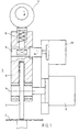
- the embossing tool 1 shown in FIG. 1 is used in a workpiece 2 (e.g. a sheet metal part) an embossed marking, for example in the form of a multi-digit To memorize number.
- a type wheel 3 is used as part of the tool 1, which with an axis of rotation 4 is rotatably mounted in a holder 5 and by a positioning drive 6 is aligned with respect to the workpiece 2.
- the Embossing marks here the individual digits of the number to be embossed successively compared to the corresponding point on the workpiece 2.
- the holder 5 is continuously pressed rotating embossing eccentric 7 one or more times with high pressure on the Workpiece 2 pressed.
- the mechanical connection between the embossing eccentric 7 and the holder 5 via a plunger 8 and a coupling element 9, the pivoted by a rotary magnet 10 between its two end positions becomes.
- one end position which is also shown in Fig. 2, that Coupling element 9, the mechanical connection between the plunger 8 and the Holder 5 ago.
- the coupling element 9 by 90 ° is pivoted and in which the dashed bevel 9 ' Layer 9 "has shown, there is no mechanical connection between the stamping eccentric 7 or the plunger 8 and the holder 5.
- the stamping eccentric 7 then does not affect type wheel 3.
- a camera 11 with associated lighting 12 in one place the type wheel 3 aligned, which is rotated by 90 ° relative to the embossing point 13.
- the character observed with the camera also correlates due to the positional relationship characters to be shaped.
- Will the correct corresponding character before and / or observed during the embossing process, is also the right one embossing characters at the embossing location. So without direct observation of the embossing character or the embossing location a clear quality statement about the Embossing process can be delivered.
- the point A can be rotated into the field of view of the camera 11 before the character located at the position of the type wheel marked A in the workpiece 2.
- the camera 11 can be used to recognize whether the character is OK. If this is the case, the print wheel is rotated to the drawn position 3 and the workpiece 2 is provided with the located at the point A mark.
- the other characters for example at positions B and C , which are recorded in a corresponding manner before the embossing process with the camera 11 and examined for possible errors in a downstream image processing program. If appropriate, an error message is output in a known manner and repair of the tool 1 and / or post-treatment of the embossed character on the workpiece 2 is initiated.
- the examination of the characters at the positions A, B, C, ... with the help of the camera 11 can also be carried out additionally or alternatively after the embossing process has been carried out. In this way, damaged or soiled characters on the type wheel can be recognized during the embossing process. This is important, for example, when embossing a workpiece with a lacquer coating. Remains of paint can get stuck in the characters on the type wheel.
- the type wheel can be successively and during a workpiece change can be fully examined with the help of the camera 11. If necessary, this One test is sufficient, one quality statement for one out of several Single stamping existing stamping process without intermediate control of the to deliver individual embossing marks.
Landscapes
- Physics & Mathematics (AREA)
- Mechanical Engineering (AREA)
- Engineering & Computer Science (AREA)
- General Physics & Mathematics (AREA)
- Analytical Chemistry (AREA)
- Biochemistry (AREA)
- General Health & Medical Sciences (AREA)
- Chemical & Material Sciences (AREA)
- Immunology (AREA)
- Pathology (AREA)
- Optics & Photonics (AREA)
- Life Sciences & Earth Sciences (AREA)
- Health & Medical Sciences (AREA)
- Investigating Materials By The Use Of Optical Means Adapted For Particular Applications (AREA)
- Credit Cards Or The Like (AREA)
- Shaping Of Tube Ends By Bending Or Straightening (AREA)
- Inking, Control Or Cleaning Of Printing Machines (AREA)
Claims (3)
- Dispositif de contrôle optique d'une empreinte de marquage réalisée à l'aide d'une roue d'impression (3) dans une pièce (2) à l'aide d'une caméra (11),
caractérisé en ce que
la caméra (11) est alignée sur un endroit de la roue d'impression (3) munie d'un signe, celle-ci se trouve à une distance déterminée de 90° par rapport à l'emplacement de l'empreinte (13) et ses signes sont mis en corrélation avec le signe à imprimer (A) par rapport à la position et cet emplacement de la roue d'impression avant et/ou pendant et/ou après la réalisation de l'empreinte se trouve dans le champ de la caméra. - Procédé de contrôle optique d'une empreinte réalisée à l'aide d'une roue d'impression (3) dans une pièce (2) à l'aide d'une caméra (11),
caractérisé en ce queavant et/ou pendant et/ou après la réalisation de l'empreinte on place la roue d'impression (3) dans le champ de visée de la caméra (11) et on émet un signal de défaut si l'emplacement observé et comportant un signe de la roue d'impression, dont les signes sont mis en corrélation avec le signe (A) à imprimer du fait de la relation de position, présente une anomalie. - Procédé selon la revendication 2,
caractérisé en ce que
l'ensemble de la roue d'impression (3) est basculé dans le temps mort, successivement dans le champ de visée de la caméra (11).
Applications Claiming Priority (3)
| Application Number | Priority Date | Filing Date | Title |
|---|---|---|---|
| DE19631506 | 1996-08-03 | ||
| DE19631506A DE19631506A1 (de) | 1996-08-03 | 1996-08-03 | Vorrichtung zur optischen Kontrolle einer mit einem Typenrad in ein Werkstück eingebrachten Prägemarkierung mittels einer Kamera |
| PCT/EP1997/003729 WO1998005515A1 (fr) | 1996-08-03 | 1997-07-12 | Dispositif pour le controle optique au moyen d'une camera d'une empreinte faite sur une piece avec une roue d'impression |
Publications (2)
| Publication Number | Publication Date |
|---|---|
| EP0921952A1 EP0921952A1 (fr) | 1999-06-16 |
| EP0921952B1 true EP0921952B1 (fr) | 2001-12-05 |
Family
ID=7801781
Family Applications (1)
| Application Number | Title | Priority Date | Filing Date |
|---|---|---|---|
| EP97937475A Expired - Lifetime EP0921952B1 (fr) | 1996-08-03 | 1997-07-12 | Dispositif et methode pour le controle optique au moyen d'une camera d'une empreinte faite sur une piece avec une roue d'impression |
Country Status (5)
| Country | Link |
|---|---|
| EP (1) | EP0921952B1 (fr) |
| DE (2) | DE19631506A1 (fr) |
| ES (1) | ES2168658T3 (fr) |
| WO (1) | WO1998005515A1 (fr) |
| ZA (1) | ZA976708B (fr) |
Cited By (1)
| Publication number | Priority date | Publication date | Assignee | Title |
|---|---|---|---|---|
| US9649874B2 (en) | 2013-06-06 | 2017-05-16 | Yakov Miller | Foil stamping machine |
Families Citing this family (1)
| Publication number | Priority date | Publication date | Assignee | Title |
|---|---|---|---|---|
| CN102601192A (zh) * | 2012-03-07 | 2012-07-25 | 无锡信捷电气有限公司 | 机器视觉引导的自动冲床 |
Family Cites Families (9)
| Publication number | Priority date | Publication date | Assignee | Title |
|---|---|---|---|---|
| DE3242532A1 (de) * | 1981-11-20 | 1983-07-07 | Diffracto Ltd., Windsor, Ontario | Einrichtung zur automatischen und programmierten pruefung von teilen oder werkstuecken sowie elektrooptischer taster dafuer |
| GB8331248D0 (en) * | 1983-11-23 | 1983-12-29 | Kearney & Trecker Marwin Ltd | Inspecting articles |
| DE3531898A1 (de) * | 1984-09-08 | 1986-03-27 | Fritz Wagner, Maschinenfabrik Gmbh & Co Kg, 6781 Schweix | Initialenpraegemaschine |
| DE3522251C1 (en) * | 1985-06-21 | 1987-01-22 | Integral Hydraulik Co | Machine for engraving alphanumeric or other characters into workpieces |
| DE3814499A1 (de) * | 1988-04-29 | 1989-11-09 | Alfred Zoller Gmbh & Co Kg Mas | Pruef- und einstellgeraet fuer rundlaufende, mehrschneidige werkzeuge |
| DE9017270U1 (de) * | 1990-12-19 | 1991-03-07 | Siemens AG, 8000 München | Vorrichtung zur optischen Werkzeugkontrolle |
| IES58755B2 (en) * | 1993-05-06 | 1993-11-03 | Sten Johan Hakansson Bjorsell | Automatic drill bit quality and position control |
| US5441589A (en) * | 1993-06-17 | 1995-08-15 | Taurus Impressions, Inc. | Flat bed daisy wheel hot debossing stamper |
| DE4330783A1 (de) * | 1993-09-10 | 1995-03-16 | Otto Bihler | Stelleinrichtung in einer Bearbeitungsmaschine |
-
1996
- 1996-08-03 DE DE19631506A patent/DE19631506A1/de not_active Withdrawn
-
1997
- 1997-07-12 WO PCT/EP1997/003729 patent/WO1998005515A1/fr not_active Ceased
- 1997-07-12 EP EP97937475A patent/EP0921952B1/fr not_active Expired - Lifetime
- 1997-07-12 ES ES97937475T patent/ES2168658T3/es not_active Expired - Lifetime
- 1997-07-12 DE DE59705684T patent/DE59705684D1/de not_active Expired - Lifetime
- 1997-07-28 ZA ZA9706708A patent/ZA976708B/xx unknown
Cited By (1)
| Publication number | Priority date | Publication date | Assignee | Title |
|---|---|---|---|---|
| US9649874B2 (en) | 2013-06-06 | 2017-05-16 | Yakov Miller | Foil stamping machine |
Also Published As
| Publication number | Publication date |
|---|---|
| DE59705684D1 (de) | 2002-01-17 |
| EP0921952A1 (fr) | 1999-06-16 |
| ZA976708B (en) | 1998-02-10 |
| ES2168658T3 (es) | 2002-06-16 |
| WO1998005515A1 (fr) | 1998-02-12 |
| DE19631506A1 (de) | 1998-02-05 |
Similar Documents
| Publication | Publication Date | Title |
|---|---|---|
| DE69220340T2 (de) | Verfahren zur Randschleifdatenübertragung an eine numerische Steuerung einer Brillenglasrandschleifmaschine | |
| EP3475027B1 (fr) | Installation d'usinage d'éléments formant flans circulaires | |
| DE102013217674A1 (de) | Vorrichtung zum Ausrichten von Komponenten einer Rundläufermaschine | |
| DE102010012858A1 (de) | Vorrichtung und Verfahren zur rotatorischen Ausrichtung eines Tubenkopfes relativ zu einem Tubenkörper | |
| AT516761B1 (de) | Verfahren und Anlage für das Richten von metallischen Teilen | |
| EP0664214B1 (fr) | Procédé et dispositif pour le montage en registre de clichés d'impression tubulaires | |
| EP3377872A1 (fr) | Procédé de marquage et de tri de pneumatiques et dispositif pour la mise en oeuvre du procédé | |
| DE3027089C2 (de) | Vorrichtung zum Messen und Korrigieren der Lenkgeometrie von Kraftfahrzeugen | |
| DE3781525T2 (de) | Verfahren und vorrichtung zur selbsttaetigen einstellung des abfahrtpunktes einer einspritzgiessvorrichtung. | |
| DE102009023475A1 (de) | Verfahren und Vorrichtung zur Generierung eines variablen Bewegungsprofils für eine Antriebseinheit einer Maschine | |
| EP0921952B1 (fr) | Dispositif et methode pour le controle optique au moyen d'une camera d'une empreinte faite sur une piece avec une roue d'impression | |
| EP4286094B1 (fr) | Procédé et dispositif d'usinage pour l'affûtage de lames d'un outil de coupe rotatif | |
| DE2416120A1 (de) | Verfahren zum ausmessen von geometrischen parametern mechanischer werkstuecke | |
| DE102022122210B4 (de) | Verfahren zum Betreiben eines Blechumformwerkzeugs, Vorrichtung und Blechumformwerkzeug | |
| DE102006056388B3 (de) | Vorrichtung zur Markierung eines Werkstückes, Markierungsprüfeinheit für eine solche Vorrichtung sowie Verfahren zur Markierungsprüfung | |
| DE3341294C2 (fr) | ||
| DE2852157A1 (de) | Verfahren und vorrichtung zum ausrichten der achse eines zylindrischen werkstuecks | |
| EP1744231A2 (fr) | Dispositif et méthode de contrôle de qualité pour marquages | |
| DE102018102692A1 (de) | Messmodul zur Kalibrierung einer Behälterbehandlungsvorrichtung | |
| WO2005037460A1 (fr) | Procede et dispositif pour travailler des pieces par formage | |
| DE19532222C2 (de) | Verfahren zum Herstellen von Walzenkonturen | |
| WO2021148505A1 (fr) | Procédé et système de caractérisation automatique d'une pièce à usiner pendant un processus d'usinage utilisant une machine-outil | |
| DE3517595A1 (de) | Maschine zur automatischen pruefung der felgen von kraftfahrzeug-scheibenraedern | |
| DE102023136188A1 (de) | Verfahren zum Ermitteln der ortsabhängigen Strukturtiefe einer Flexodruckform | |
| DE102011085784B3 (de) | Messsystem und Verfahren zur Vermessung von Bauteilen |
Legal Events
| Date | Code | Title | Description |
|---|---|---|---|
| PUAI | Public reference made under article 153(3) epc to a published international application that has entered the european phase |
Free format text: ORIGINAL CODE: 0009012 |
|
| 17P | Request for examination filed |
Effective date: 19981116 |
|
| AK | Designated contracting states |
Kind code of ref document: A1 Designated state(s): BE DE ES FR GB IT SE |
|
| 17Q | First examination report despatched |
Effective date: 19990902 |
|
| RIC1 | Information provided on ipc code assigned before grant |
Free format text: 7B 44B 5/00 A, 7B 23Q 17/24 B, 7B 23Q 17/09 B, 7B 23Q 11/00 B, 7G 01B 11/02 B, 7G 01N 21/88 B |
|
| RTI1 | Title (correction) |
Free format text: DEVICE AND METHOD FOR OPTICALLY CONTROLLING BY MEANS OF A CAMERA A MARK STAMPED ON A WORKPIECE BY MEANS OF A TYPE WHEEL |
|
| GRAG | Despatch of communication of intention to grant |
Free format text: ORIGINAL CODE: EPIDOS AGRA |
|
| GRAG | Despatch of communication of intention to grant |
Free format text: ORIGINAL CODE: EPIDOS AGRA |
|
| GRAH | Despatch of communication of intention to grant a patent |
Free format text: ORIGINAL CODE: EPIDOS IGRA |
|
| GRAH | Despatch of communication of intention to grant a patent |
Free format text: ORIGINAL CODE: EPIDOS IGRA |
|
| GRAA | (expected) grant |
Free format text: ORIGINAL CODE: 0009210 |
|
| AK | Designated contracting states |
Kind code of ref document: B1 Designated state(s): BE DE ES FR GB IT SE |
|
| REG | Reference to a national code |
Ref country code: GB Ref legal event code: IF02 |
|
| GBT | Gb: translation of ep patent filed (gb section 77(6)(a)/1977) |
Effective date: 20011205 |
|
| REF | Corresponds to: |
Ref document number: 59705684 Country of ref document: DE Date of ref document: 20020117 |
|
| ET | Fr: translation filed | ||
| REG | Reference to a national code |
Ref country code: ES Ref legal event code: FG2A Ref document number: 2168658 Country of ref document: ES Kind code of ref document: T3 |
|
| PLBE | No opposition filed within time limit |
Free format text: ORIGINAL CODE: 0009261 |
|
| STAA | Information on the status of an ep patent application or granted ep patent |
Free format text: STATUS: NO OPPOSITION FILED WITHIN TIME LIMIT |
|
| 26N | No opposition filed | ||
| PGFP | Annual fee paid to national office [announced via postgrant information from national office to epo] |
Ref country code: ES Payment date: 20070621 Year of fee payment: 11 |
|
| PGFP | Annual fee paid to national office [announced via postgrant information from national office to epo] |
Ref country code: GB Payment date: 20070726 Year of fee payment: 11 |
|
| PGFP | Annual fee paid to national office [announced via postgrant information from national office to epo] |
Ref country code: SE Payment date: 20070704 Year of fee payment: 11 Ref country code: IT Payment date: 20070726 Year of fee payment: 11 Ref country code: BE Payment date: 20070726 Year of fee payment: 11 |
|
| PGFP | Annual fee paid to national office [announced via postgrant information from national office to epo] |
Ref country code: FR Payment date: 20070730 Year of fee payment: 11 |
|
| EUG | Se: european patent has lapsed | ||
| GBPC | Gb: european patent ceased through non-payment of renewal fee |
Effective date: 20080712 |
|
| REG | Reference to a national code |
Ref country code: FR Ref legal event code: ST Effective date: 20090331 |
|
| PG25 | Lapsed in a contracting state [announced via postgrant information from national office to epo] |
Ref country code: GB Free format text: LAPSE BECAUSE OF NON-PAYMENT OF DUE FEES Effective date: 20080712 |
|
| PG25 | Lapsed in a contracting state [announced via postgrant information from national office to epo] |
Ref country code: IT Free format text: LAPSE BECAUSE OF NON-PAYMENT OF DUE FEES Effective date: 20080712 Ref country code: FR Free format text: LAPSE BECAUSE OF NON-PAYMENT OF DUE FEES Effective date: 20080731 |
|
| REG | Reference to a national code |
Ref country code: ES Ref legal event code: FD2A Effective date: 20080714 |
|
| PG25 | Lapsed in a contracting state [announced via postgrant information from national office to epo] |
Ref country code: ES Free format text: LAPSE BECAUSE OF NON-PAYMENT OF DUE FEES Effective date: 20080714 |
|
| PG25 | Lapsed in a contracting state [announced via postgrant information from national office to epo] |
Ref country code: SE Free format text: LAPSE BECAUSE OF NON-PAYMENT OF DUE FEES Effective date: 20080713 Ref country code: BE Free format text: LAPSE BECAUSE OF NON-PAYMENT OF DUE FEES Effective date: 20080731 |
|
| PGFP | Annual fee paid to national office [announced via postgrant information from national office to epo] |
Ref country code: DE Payment date: 20100903 Year of fee payment: 14 |
|
| PG25 | Lapsed in a contracting state [announced via postgrant information from national office to epo] |
Ref country code: DE Free format text: LAPSE BECAUSE OF NON-PAYMENT OF DUE FEES Effective date: 20120201 |
|
| REG | Reference to a national code |
Ref country code: DE Ref legal event code: R119 Ref document number: 59705684 Country of ref document: DE Effective date: 20120201 |