EP0921955B1 - Pneu pour materiel agricole de type industriel - Google Patents
Pneu pour materiel agricole de type industriel Download PDFInfo
- Publication number
- EP0921955B1 EP0921955B1 EP96935786A EP96935786A EP0921955B1 EP 0921955 B1 EP0921955 B1 EP 0921955B1 EP 96935786 A EP96935786 A EP 96935786A EP 96935786 A EP96935786 A EP 96935786A EP 0921955 B1 EP0921955 B1 EP 0921955B1
- Authority
- EP
- European Patent Office
- Prior art keywords
- lug
- tread
- lugs
- shoulder
- tire
- Prior art date
- Legal status (The legal status is an assumption and is not a legal conclusion. Google has not performed a legal analysis and makes no representation as to the accuracy of the status listed.)
- Expired - Lifetime
Links
- 230000002787 reinforcement Effects 0.000 claims description 7
- 239000011324 bead Substances 0.000 description 12
- 239000004677 Nylon Substances 0.000 description 4
- 229920001778 nylon Polymers 0.000 description 4
- 229920000728 polyester Polymers 0.000 description 4
- 230000003014 reinforcing effect Effects 0.000 description 4
- 239000002689 soil Substances 0.000 description 4
- 230000008520 organization Effects 0.000 description 3
- 239000004760 aramid Substances 0.000 description 2
- 229920003235 aromatic polyamide Polymers 0.000 description 2
- 239000004744 fabric Substances 0.000 description 2
- 241000254043 Melolonthinae Species 0.000 description 1
- 229910000831 Steel Inorganic materials 0.000 description 1
- 230000001154 acute effect Effects 0.000 description 1
- 238000004140 cleaning Methods 0.000 description 1
- 150000001875 compounds Chemical class 0.000 description 1
- 238000010276 construction Methods 0.000 description 1
- 238000005034 decoration Methods 0.000 description 1
- 230000000694 effects Effects 0.000 description 1
- 239000000945 filler Substances 0.000 description 1
- 238000002372 labelling Methods 0.000 description 1
- 239000000463 material Substances 0.000 description 1
- 238000005259 measurement Methods 0.000 description 1
- 238000012856 packing Methods 0.000 description 1
- 210000000006 pectoral fin Anatomy 0.000 description 1
- 230000001681 protective effect Effects 0.000 description 1
- 239000010959 steel Substances 0.000 description 1
Images



Classifications
-
- B—PERFORMING OPERATIONS; TRANSPORTING
- B60—VEHICLES IN GENERAL
- B60C—VEHICLE TYRES; TYRE INFLATION; TYRE CHANGING; CONNECTING VALVES TO INFLATABLE ELASTIC BODIES IN GENERAL; DEVICES OR ARRANGEMENTS RELATED TO TYRES
- B60C11/00—Tyre tread bands; Tread patterns; Anti-skid inserts
- B60C11/03—Tread patterns
- B60C11/0311—Patterns comprising tread lugs arranged parallel or oblique to the axis of rotation
Definitions
- This invention relates to a pneumatic agricultural tire for an industrial type tractor or like vehicle.
- R-4 service Farm tire designs for industrial service are classified as R-4 service. Overall R-4 service is quite severe and typically involves high loads at a large degree of roading. The vehicles to which the tires are mounted typically are exposed to large amounts of debris, hard packed soil conditions and high load service conditions.
- tires are generally relatively small and typically have a nominal rim diameter of 28" (71 cm) or less. They generally have a nonskid depth at the centerline of the tire at approximately 1" (2.54 cm).
- a typical tire may be a 19.5LR24 tire.
- This tire when produced in a radial construction will have a carcass with 3 to 4 plies of synthetic cord reinforcement.
- the cords generally are nylon or polyester.
- the carcass will further include four belts of high flex polyester, nylon or aramid. Historically, these tires have been all fabric reinforced in order to provide better ride and handling.
- the most relevant prior art corresponding to the preamble of claim 1 is Japanese Publication No. 57167802, the tire of this invention travels well on both good and soft roads. Its tread pattern consists of three regions with almost the same width. At the two side regions, lugs are arranged alternately on the tire circumference to form arrowhead pattern. They are at an acute angle to the tire equator. At the central region, independent long blocks are laid across the tire equator. Each block is placed on a line extended from the longitudinal centerline of one lug located on one of the side regions. The adjacent blocks face each other and overlap for a certain range but separated by a groove along the equator.
- a pneumatic agricultural tire 20 for an industrial type tractor or like vehicle having a maximum section width an axis of rotation, an equatorial plane (EP), centered between the maximum section width and being perpendicular to the axis, a casing having a belt reinforcement structure 26 and a carcass 21 reinforced with rubber coated cords, a rubber tread 32 disposed radially outward of the carcass 21 and belt 26, the tread 32 being divided on each side of the equatorial plane into a first and second tread half, the tread has a pair of lateral edges 33A,33B, the distance between the lateral edges defines the tread width.
- the tread 32 has an inner tread 34 and a plurality of tread lugs 40,50 projecting radially from the inner tread 34.
- the tread 32 has a plurality of central lugs 50 and a plurality of shoulder lugs 40.
- the plurality of central lugs 50 are arranged in a circumferentially continuous row 60 and extend across the equatorial plane (EP).
- Each central lug 50 preferably is similar in shape and in orientation relative to each circumferentially adjacent central lug 50.
- Each central lug 50 has a leading end 51 and a trailing end 53. The leading end 51 of each central lug 50 is located on an opposite side of the equatorial plane relative to the trailing end 53 of the same central lug 50.
- the plurality of shoulder lugs 40 are divided into first and second rows.
- One row 44,46 extends from each of the lateral edges 33A,33B towards the equatorial plane of the tire 20.
- the shoulder lugs 40 have an axially inner end 41 axially spaced from a leading end 51 and a trailing end 53 of the axially adjacent central lugs 50.
- the shoulder lugs 40 extending from each lateral edge 33A,33B are similar in shape and have an overall lug length of 40% of the tread width.
- Each shoulder lug 40 is located within one tread half 32A or 32B.
- the shoulder lugs 40 and central lugs 50 are axially spaced at the outer surface 58 of the lug 40,50 such that the axially inner ends 41 of the first and second rows 44,46 of shoulder lugs 40 are axially aligned within each respective row 44,46 and the leading ends 51 and trailing ends 53 of the central lugs 50 are respectively axially aligned.
- a plane P 1 tangent to the axially inner ends 41 of the first row 44 of shoulder lugs 40 is spaced an axial distance d 1 from a plane C T tangent to the trailing ends 53 of the central lugs 50.
- a plane P 2 tangent to the axially aligned inner ends 41 of the second row 46 of shoulder lugs 40 is spaced a distance d 2 from a plane C L , the plane C L being tangent to the leading ends of the central lugs.
- the distances d 1 and d 2 form two circumferentially continuous straight channels around the periphery of the tread. In the preferred embodiment the distances d 1 and d 2 are equal and are about 5 % of the tread width.
- the planes C T and C L are each located an axial distance of at least 5 % of the tread width or more from the equatorial plane. Preferably the planes C T and C L are equally spaced from the equatorial plane a distance greater than 10%.
- the shoulder lugs 40 of the first and second rows 44,46 are oppositely oriented and similarly inclined relative to the shoulder lugs 40 of the opposite row 44,46.
- the tire tread 32 is a nondirectional tread having equal traction in both the forward and reverse direction.
- the shoulder lugs of the first and second rows are oppositely oriented and oppositely inclined relative to the shoulder lugs of the opposite row.
- the tire tread is directional and has a superior tractive capability in the forward direction when the tire is mounted such that the leading ends contact the ground first as the tire rolls.
- the tire in either case has a very open tread pattern for its application and when the tire is normally inflated and loaded the tread has a net-to-gross ratio of less than 35% preferably about 30%.
- These tires typically have nominal rim diameter of 28" (71 cm) or less and a tread lug height that is measured from the inner tread to the radially outer surface of the lug at the equatorial plane, the lug height being an industrially standard R-4 lug height.
- Each shoulder lug and central lug has a surface area centroid M.
- the centroid M of the first row shoulder lug, a central lug and a second row shoulder lug lie on a substantially straight line S L .
- S L is inclined in a range of 35° to 45° relative to an axial plane.
- the shoulder lugs of the first and second row and the central lugs each have lug center lines intersecting the centroid M of the respective lugs.
- the lug centerlines are substantially aligned with the line S L .
- each shoulder lug and central lug has a centroid M, the centroid of the first or second shoulder lug and a central lug lie in a substantially straight line S L2 , S L2 being inclined in the range of 35 ° to 45 ° relative to an axial plane.
- Each shoulder lug and central lug have a center line intersecting the centroids M of the respective lugs.
- the lug centerlines of the first shoulder lug and the central lug are substantially aligned with the line L 2 .
- the shoulder lug center line of the second row lug is similarly but oppositely inclined relative to the line S L2 .
- Axial and “axially” means the lines or directions that are parallel to the axis of rotation of the tire.
- Bead or “Bead Core” means generally that part of the tire comprising an annular tensile member, the radially inner beads which are associated with holding the tire to the rim being wrapped by ply cords and shaped, with or without other reinforcement elements such as flippers, chippers, apexes or fillers, toe guards and chafers, the bead or beads under the tread being encapsulated in tread rubber can be with or without other cord reinforced fabric elements.
- Belt Structure or “Reinforcing Belts” means at least two annular layers or plies of parallel cords, woven or unwoven, underlying the tread, unanchored to the bead, and having both left and right cord angles in the range from 17° to 27° with respect to the equatorial plane of the tire.
- “Bias Ply Tire” means that the reinforcing cords in the carcass ply extend diagonally across the tire from bead-to-bead at about a 25-65 ° angle with respect to the equatorial plane of the tire, the ply cords running at opposite angles in alternate layers.
- Carcass means a laminate of tire ply material and other tire components cut to length suitable for splicing, or already spliced, into a cylindrical or toroidal shape. Additional components may be added to the carcass prior to its being vulcanized to create the molded tire.
- “Circumferential” means lines or directions extending along the perimeter of the surface of the annular tread perpendicular to the axial direction.
- Design Rim means a rim having a specified configuration and width.
- the design rim and design rim width are as specified by the industry standards in effect in the location in which the tire is made.
- the design rims are as specified by the Tire and Rim Association.
- the rims are as specified in the European Tyre and Rim Technical Organization--Standards Manual and the term design rim means the same as the standard measurement rims.
- the standard organization is The Japan Automobile Tire Manufacturer's Association.
- Design Rim Width is the specific commercially available rim width assigned to each tire size and typically is between 75% and 90% of the specific tire's section width.
- Equatorial Plane means the plane perpendicular to the tire's axis of rotation and passing through the center of its tread.
- “Footprint” means the contact patch or area of contact of the tire tread with a flat surface at zero speed and under normal load and pressure.
- “Lateral Edge” means the axially outermost edge of the tread as defined by a plane parallel to the equatorial plane and intersecting the outer ends of the axially outermost traction lugs at the radial height of the inner tread surface.
- Leading refers to a portion or part of the tread that contacts the ground first, with respect to a series of such parts or portions, during rotation of the tire in the direction of travel.
- Net-to-gross Ratio means the ratio of the surface area of the normally loaded and normally inflated tire tread rubber that makes contact with a hard flat surface, divided by the total area of the tread, including noncontacting portions such as grooves as measured around the entire circumference of the tire.
- Normal Inflation Pressure means the specific design inflation pressure assigned by the appropriate standards organization for the service condition for the tire.
- Normal Load means the specific design inflation load assigned by the appropriate standards organization for the service condition for the tire.
- Ring and radially mean directions radially toward or away from the axis of rotation of the tire.
- Ring Ply Tire means a belted or circumferentially-restricted pneumatic tire in which the ply cords which extend from bead to bead are laid at cord angles between 65° and 90° with respect to the equatorial plane of the tire.
- “Section Height” means the radial distance from the nominal rim diameter to the outer diameter of the tire at its equatorial plane.
- “Section Width” means the maximum linear distance parallel to the axis of the tire and between the exterior of its sidewalls when and after it has been inflated at normal pressure for 24 hours, but unloaded, excluding elevations of the sidewalls due to labeling, decoration or protective bands.
- Tire Design Load is the base or reference load assigned to a tire at a specific inflation pressure and service condition; other load-pressure relationships applicable to the tire are based upon that base or reference.
- Trailing refers to a portion or part of the tread that contacts the ground last, with respect to a series of such parts or portions during rotation of the tire in the direction of travel.
- Tread Arc Width means the width of an arc having its center located on the plane (EP) and which substantially coincides with the radially outermost surfaces of the various traction elements (lugs, blocks, buttons, ribs, etc.) across the lateral or axial width of the tread portions of a tire when the tire is mounted upon its designated rim and inflated to its specified inflation pressure but not subject to any load.
- Thread Width means the arc length of the tread surface in the axial direction, that is, in a plane parallel to the axis of rotation of the tire.
- Unit Tread Pressure means the radial load borne per unit area (square centimeter or square inch) of the tread surface when that area is in the footprint of the normally inflated and normally loaded tire.
- Fig. 1 is a perspective view of a first embodiment tire according to the invention.
- Fig. 2 is a plan view of the tire of Fig. 1.
- Fig. 3 is an enlarged fragmentary view of a portion of the tread of the tire taken from Fig. 2.
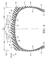
- Fig. 4 is a cross-sectional view of the tire taken along lines 4-4 of Fig. 2.
- Fig. 5 is a plan view of a portion of the contact patch of the first embodiment tire according to the present invention.
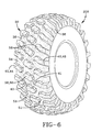
- Fig. 6 is a perspective view of a second embodiment tire according to the invention.
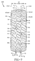
- Fig. 7 is a plan view of the tire of Fig. 6.
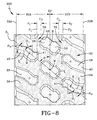
- Fig. 8 is an enlarged fragmentary view of a portion of the tread of the tire taken from Fig. 7.
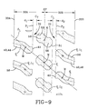
- Fig. 9 is a plan view of a portion of the contact patch of the second embodiment tire according to the present invention.
- a tire is shown in cross-sectional view generally as reference numeral 20.
- the tire has a carcass 21 having one or more carcass plies 22 extending circumferentially about the axis rotation of the tire.
- the tire preferably has 3 to 4 cord reinforced plies having synthetic nylon or polyester cords.
- the carcass plies are anchored around a pair of substantially inextensible annular beads 24.
- a belt reinforcing member 26 has one or more belt plies disposed radially outward from the carcass plies.
- Preferably four belts are employed.
- the belts being of a polyester, nylon or aramid cord reinforcement alternatively the cords can be of an ultra high tensile monofilament steel cord reinforcement.
- These belt plies provide reinforcement for the crown region of the tire 20.
- a circumferentially extending tread 32 is located radially outwardly of the belt reinforcing structure 26.
- a sidewall portion 33 extends radially inwardly from each axial or lateral tread edge 33A,33B of the tread to an annular bead portion 35 having the beads 24 located therein.
- Carcass plies 22 preferably have the cords oriented radially. The number of plies depends on the load carrying requirements of the tire. This tire carcass and belt structure as shown in Fig. 4 is equally applicable for use in both embodiments of the present invention.
- Figs. 1-5 illustrate a directional tread made in accordance to the present invention, whereas Figs. 6-9 illustrate a tread pattern made in a nondirectional fashion.
- the tire 20 according to the present invention has a unique directional tread 32.
- the tread 32 has a first tread edge 33A and a second tread edge 33B.
- Disposed between the tread edges 33A and 33B is an inner tread 34 and a plurality of central lugs 50 extending radially outwardly from the inner tread 34.
- each central lug 50 has a radially outer surface 58, a leading first edge 52, a trailing second edge 54, and a center line between the first and second edges.
- Each central lug 50 extends generally circumferential from a leading end 51 to a trailing end 53.
- the average distance along the center line 63 between the leading and trailing ends 51,53 defines the total lug length L 1 of the central lug.
- the length L 1 is at least 10% of the tread width, preferably about 30%.
- the distance extending substantially perpendicularly between the first and second edges 52,54 of the central lug 50 defines the lug width.
- the radial distance extending between the inner tread 34 and the tread edges 52,54 of the lug defines the radial lug height (l h ).
- the lug height preferably is an R-4 type lug height as specified by the Tire & Rim Industry standard for industrial service applications.
- the central lugs 50 are arranged in a circumferentially repeating row 60 of lugs 50, each lug 50 extends crossing the equatorial plane (EP).
- the circumferentially adjacent central lugs 50 are similarly oriented.
- Each lug 50 preferably lies equally within each of the respective tread halves 32A or 32B.
- the leading ends 51 as shown lie entirely within tread half 32A while the trailing ends 53 lie entirely the tread half 32B.
- These central lugs 50 have an enlarged lug head 55 at both the trailing and leading ends 51,53 of the lug 50.
- the width of the lugs 50 is enlarged relative to the shoulder lugs 40. This enlarged lug 50 is extremely durable and provides excellent traction and ride performance.
- the ride performance and traction capabilities are further enhanced by the employment of a plurality of shoulder lugs 40 which extend from each respective tread edge 33A or 33B and lie entirely within one tread half 32A or 32B.
- the shoulder lugs 40 have a total lug length L 1 equal to or greater than the total lug length L 1 of the central lug 50. As shown, the shoulder lugs have a lug length L 1 of about 35% .
- the shoulder lugs are divided into two rows: a first row 44 and a second row 46.
- the first row 44 of shoulder lugs 40 has an axially inner end 41 that is located circumferentially between the trailing end 53 of circumferentially adjacent central lugs 50.
- the second row 46 of shoulder lugs 40 extends from the tread edge 33B and have a length substantially equal to the length of the first row of shoulder lugs.
- the second row 46 of shoulder lugs 40 have an axially inner end 41 that is circumferentially located between the leading ends 51 of circumferentially adjacent central lugs 50.
- both the first row 44 and second row 46 of shoulder lugs 40 have preferably a compound inclination, the axially inner inclination ⁇ i being about 45° relative to the equatorial plane and the axially outer inclination ⁇ o being about 60° relative to the equatorial plane.
- the central lug 50 has a middle portion which has a center line 63 intersecting the leading and trailing ends 51, 53 lying between edges 52,54.
- the centerline 63 is oriented at an angle ⁇ of less than 50° preferably less than 45° relative to the equatorial plane.
- the net-to-gross ratio of the tread is less than 35%.
- the space between the lugs creates large soil discharge channels 36. These channels create a very open tread pattern. The openness of the tread pattern further enhances the self-cleaning properties of the tread 32 keeping it from packing with mud.
- lugs 40,50 can vary the overall shape of the lugs 40,50 and can modify the general orientation or appearance of the lugs.
- first row 44 and second row 46 of shoulder lugs 40 and the central lugs 50 are axially spaced at the outer surface 58 of the lugs 40,50 such that the axially inner ends 41 of the first and second rows 44,46 of shoulder lugs 40 are axially aligned within each respective row 44,46.
- the leading ends 51 and the trailing ends 53 of the central lugs 50 are also respectively axially aligned.
- a plane P 1 is tangent to the inner ends 41 of the first row 44 of shoulder lugs 40 and is spaced an axial distance d 1 from a plane C T tangent to the trailing ends 53 of the central lugs 50.
- a plane P 2 tangent to the axially inner ends 41 of the second row 46 of the shoulder lugs 40 is spaced a distance d 2 from a plane C L .
- the plane C L is tangent to the leading ends 51 of the central lugs 50.
- the distances d 1 and d 2 form two circumferentially continuous straight channels 70 around the periphery of the tread 32.
- the agricultural tire preferably has the distances d 1 and d 2 being equal and the planes C T and C L each located an axial distance of 5 % of the tread width or more from the equatorial plane (EP) as illustrated.
- the planes C T and C L are equally spaced from the equatorial plane (EP) a distance of at least 10% of the tread width.
- the tire 20 as shown in Figs. 1-5 has a directional tread 32 with the first and second rows 44,46 of shoulder lugs 40 oppositely oriented and oppositely inclined relative to the shoulder lugs 40 of the opposite row.
- a tread 32 of the second embodiment tire 200 is shown having a nondirectional tread pattern.
- the same reference numerals are used, the only difference lies in the treads 32, the tread 32 of tire 200 having the first row 44 of shoulder lugs 40 oppositely oriented but similarly inclined relative to the shoulder lugs 40 of the opposite row 46 as can be seen from the perspective view of Fig. 6 and the plan view of Fig. 7, the lugs 40 and 50 extending in a substantially linear fashion across the tread 32.
- the tread 32 exhibits a net-to-gross ratio of less than 35 % preferably about 30%.
- Both tires 20,200 exhibit a nominal rim diameter of 28" (71 cm) or less and a tread lug height (l h ) that is measured from the inner tread 34 to the radially outer surface 58 of the lugs 50 at the equatorial plane of an industry standard R-4 lug height.
- l h tread lug height
- the nonskid depth at the centerline of the tires 20,200 will be approximately one inch (2.5 cm).
- each tire 20,200 has each shoulder lug 40 and each central lug 50 having a surface area centroid M.
- the nondirectional tire 200 of figure 9 has the centroids M of the first row shoulder lug 40, a central lug 50, and a second row shoulder lug 40 lie on a substantially straight line S L , S L being inclined in the range 35° to 45° relative to an axial plane as illustrated in Figs. 6-9.
- This tire 200 illustrated in Figs. 6-9 has the shoulder lugs 40 of the first and second row 44,46 and the central lugs 50 each having lug centerlines C L intersecting the centroid M of the respective lugs.
- the lug centerlines C L are substantially aligned with the line S L .
- the pneumatic agricultural tire 20 of Figs. 1-5 have each shoulder lug 40 and each central lug 50 having a surface area centroid M, the centroid M of the first or second shoulder lug 40 and the central lug 50 lie in a substantially straight line S L2 , S L2 being inclined in the range of 35° to 45° relative to an axial plane.
- This pneumatic agricultural tire 20 of Figs. 1-5 has each shoulder lug and central lug each having a lug centerline C L intersecting the centroids M of the respective lugs.
- the lug centerlines C L of the first row 44 of shoulder lugs 40 and the row 60 of central lugs 50 are substantially aligned with the straight line S L2 where the shoulder lug 40 centerline C L of the second row 46 is similarly but oppositely inclined relative to the line S L2 .
- the tires 20,200 have a constant tread arc at the shoulder, the nonskid depth increases to approximately 125% to 175%, preferably 150%, of the nonskid depth as measured from the equatorial plane (EP) of the tires 20,200.
- EP equatorial plane
- the center of the tread bears most of the load carrying capacity while the shoulder regions are provided to increase traction and provide additional biting or digging surfaces which provide traction particularly in loose soil or loose debris. It is believed preferable that the tread lugs 40,50 be reasonably braced using generous angles to further enhance the stiffness of the lugs and to improve its durability.
- a novel feature of the directional tread pattern of the tire 20 as in Figs. 1-5 of the first embodiment and the nondirectional tread pattern of Figs. 6-9 of the second embodiment tire 200 is that the lugs 40 of the first row 44 and the lugs 40 of the second row 46 do not axially overlap at the equatorial plane.
- the central lugs 50 do not overlap or interlock with either the first or the second rows 44,46 of shoulder lugs 40.
- this feature is not believed to have been employed in this type of tire heretofore.
- the benefits of this feature are that the tread pattern remains relatively open increasing the overall tractive performance of the tire while not sacrificing the overall ride performance.
- the description of the tire 20 of the first embodiment applies to the tire 200 of the second embodiment, the only difference being the orientation of the lugs 40 of the second row 46 of tire 20 and tire 200. In all other aspects the tires are the same.
Landscapes
- Engineering & Computer Science (AREA)
- Mechanical Engineering (AREA)
- Tires In General (AREA)
Claims (13)
- Bandage pneumatique agricole (20) pour un tracteur de génie civil ou pour un véhicule analogue possédant une grosseur du boudin maximale, un axe de rotation, un plan équatorial (EP) centré entre la grosseur du boudin maximale et perpendiculaire à l'axe, une enveloppe possédant une structure de renforcement de ceinture (26) et une carcasse (21) renforcée avec des câblés enrobés de caoutchouc, une bande de roulement de caoutchouc (32) disposée en direction radiale à l'extérieur de la carcasse, la bande de roulement étant subdivisée de part et d'autre du plan équatorial (EP) en une première et en une deuxième moitié de bande de roulement (32A, 32B), la bande de roulement possède une paire de bords de bande de roulement latéraux (33A, 33B), la distance entre les bords de bande de roulement définit la largeur de bande de roulement, la bande de roulement possède une bande de roulement interne (34) et plusieurs barrettes de bande de roulement (40, 50) faisant saillie en direction radiale par rapport à la bande de roulement interne (34), la bande de roulement (32) comportant:plusieurs barrettes centrales (50) disposées en une rangée continue (60) en direction circonférentielle et s'étendant à travers le plan équatorial (EP), chaque barrette centrale (50) étant de forme et d'orientation similaires à celles de chaque barrette centrale (50) adjacente en direction circonférentielle, chaque barrette centrale (50) possédant une extrémité avant (51) et une extrémité arrière (53), l'extrémité avant (51) de chaque barrette centrale (50) étant située sur le côté du plan équatorial (EP) opposé à celui occupé par l'extrémité arrière (53) de la même barrette centrale, les barrettes centrales (50) possédant une longueur globale représentant au moins 10% de la largeur de bande de roulement;plusieurs barrettes d'épaulement (40) subdivisées en première et deuxième rangées (44, 46), une rangée (44, 46) s'étendant depuis chacun des bords de bande de roulement latéraux (33A, 33B) jusqu'au plan équatorial du pneumatique (20), les barrettes d'épaulement (40) possédant une extrémité interne (41) en direction axiale espacée en direction axiale de l'extrémité avant (51) et de l'extrémité arrière (53) de barrette centrale (50) adjacente en direction axiale, les barrettes d'épaulement (40) s'étendant depuis chaque bord de bande de roulement latéral étant de configuration similaire et possédant une longueur de barrette globale représentant plus de 30% de la largeur de la bande de roulement, chaque barrette d'épaulement (40) étant située dans les limites d'une demi-bande de roulement, les barrettes d'épaulement (40) et les barrettes centrales (50) étant espacées en direction axiale à la surface externe (58) des barrettes (40, 50) de telle sorte que les extrémités internes en direction axiale (41) des première et deuxième rangées (44, 46) de barrettes d'épaulement (40) sont disposées en alignement axial dans les limites de chaque rangée respective, les extrémités avant (51) et les extrémités arrières (53) des barrettes centrales (50) étant disposées respectivement en alignement axial,la bande de roulement étant caractérisée en ce qu'un plan P1 tangent aux extrémités internes (41) en direction axiale de la première rangée (44) de barrettes d'épaulement (40) est espacé sur une distance axiale d1 par rapport à un plan CT tangent aux extrémités arrières (53) des barrettes centrales (50) et en ce qu'un plan P2 tangent aux extrémités internes (41) disposées en alignement axial de la deuxième rangée (46) de barrettes d'épaulement (40) est espacé sur une distance d2 par rapport à un plan CL, le plan CL étant tangent aux extrémités avant (51) des barrettes centrales (50), les distances d1 et d2 représentant au moins 5% de la largeur de bande de roulement et formant deux canaux rectilignes continus en direction circonférentielle autour de la périphérie de la bande de roulement (32).
- Bandage pneumatique agricole (20) selon la revendication 1, dans lequel la barrette centrale (50) possède une longueur de barrette représentant environ 30% de la largeur de bande de roulement.
- Bandage pneumatique agricole (20) selon la revendication 2, dans lequel les distances d1 et d2 sont égales.
- Bandage pneumatique agricole (20) selon la revendication 2, dans lequel les plans CT et CL sont chacun espacés sur une distance axiale représentant au moins 5% de la largeur de bande de roulement ou plus par rapport au plan équatorial (EP).
- Bandage pneumatique agricole (20) selon la revendication 2, dans lequel les plans CT et CL sont équidistants par rapport au plan équatorial (EP).
- Bandage pneumatique agricole (20) selon la revendication 1, dans lequel des barrettes d'épaulement (40) des première et deuxième rangées (44, 46) présentent une orientation opposée et une inclinaison similaire par rapport à celles des barrettes d'épaulement (40) de la rangée opposée (44, 46).
- Bandage pneumatique agricole (20) selon la revendication 1, dans lequel les barrettes d'épaulement (40) des première et deuxième rangées présentent une orientation opposée et une inclinaison opposée par rapport à celles des barrettes d'épaulement de la rangée opposée.
- Bandage pneumatique agricole (20) selon la revendication 1, dans lequel le pneumatique possède un rapport net/brut, lorsque la bande de roulement est normalement gonflée et normalement chargée, inférieur à 35%.
- Bandage pneumatique agricole (20) selon la revendication 1, dans lequel le pneumatique (20) possède un diamètre de jante nominale de 61 cm (24 pouces) ou moins et une hauteur de barrette de bande de roulement, telle que mesurée entre la bande de roulement interne (34) et la surface externe (58) de la barrette (50) en direction radiale au plan équatorial, correspondant à une hauteur de barrette normale pour le génie civil de type R-4.
- Bandage pneumatique agricole (20) selon la revendication 6, dans lequel chaque barrette d'épaulement (40) et chaque barrette centrale (50) possèdent un point de concours des médianes en surface M, le point de concours des médianes M d'une barrette d'épaulement de la première rangée, d'une barrette centrale et d'une barrette d'épaulement de la seconde rangée se trouvant sur une ligne essentiellement rectiligne SL, SL présentant une inclinaison dans le domaine de 35° à 45° par rapport au plan axial.
- Bandage pneumatique agricole (20) selon la revendication 10, dans lequel les barrettes d'épaulement (40) des première et deuxième rangées (44, 46) et les barrettes centrales (50) possèdent chacune des médianes de barrettes CL coupant les points de concours des médianes M des barrettes respectives, les médianes de barrettes CL étant disposées essentiellement en alignement avec la ligne SL.
- Bandage pneumatique agricole (20) selon la revendication 7, dans lequel chaque barrette d'épaulement (40) et chaque barrette centrale (50) possède un point de concours des médianes M, le point de concours des médianes à d'une première ou d'une seconde barrette d'épaulement et de la barrette centrale se situe sur une ligne essentiellement rectiligne SL2, SL2 présentant une inclinaison dans le domaine de 35° à 45° par rapport au plan axial.
- Bandage pneumatique agricole (20) selon la revendication 12, dans lequel chaque barrette d'épaulement (40) et chaque barrette centrale (50) possède chacune une médiane de barrette CL coupant les points de concours des médianes M des barrettes respectives, les médianes d'une première barrette d'épaulement (40) et de la barrette centrale (50) étant disposées essentiellement en alignement avec la ligne SL2, tandis que la médiane de la barrette d'épaulement (40) d'une barrette de la deuxième rangée présente une inclinaison similaire, mais dans le sens opposé par rapport à la ligne SL2.
Applications Claiming Priority (1)
| Application Number | Priority Date | Filing Date | Title |
|---|---|---|---|
| PCT/US1996/013785 WO1998008697A1 (fr) | 1996-08-29 | 1996-08-29 | Pneu pour materiel agricole de type industriel |
Publications (2)
| Publication Number | Publication Date |
|---|---|
| EP0921955A1 EP0921955A1 (fr) | 1999-06-16 |
| EP0921955B1 true EP0921955B1 (fr) | 2000-05-03 |
Family
ID=22255675
Family Applications (1)
| Application Number | Title | Priority Date | Filing Date |
|---|---|---|---|
| EP96935786A Expired - Lifetime EP0921955B1 (fr) | 1996-08-29 | 1996-08-29 | Pneu pour materiel agricole de type industriel |
Country Status (8)
| Country | Link |
|---|---|
| EP (1) | EP0921955B1 (fr) |
| JP (1) | JP2000516886A (fr) |
| AU (1) | AU7358396A (fr) |
| BR (1) | BR9612721A (fr) |
| CA (1) | CA2262687A1 (fr) |
| DE (1) | DE69608142T2 (fr) |
| ES (1) | ES2145490T3 (fr) |
| WO (1) | WO1998008697A1 (fr) |
Families Citing this family (6)
| Publication number | Priority date | Publication date | Assignee | Title |
|---|---|---|---|---|
| US6450221B1 (en) | 1998-03-17 | 2002-09-17 | The Goodyear Tire & Rubber Company | Non-directional farm tire |
| WO1999047368A1 (fr) * | 1998-03-17 | 1999-09-23 | The Goodyear Tire & Rubber Company | Pneu pour materiel agricole dote d'une semelle a sculpture non directionnelle |
| US6530405B1 (en) | 1998-08-26 | 2003-03-11 | The Goodyear Tire & Rubber Company | On/off-road tread |
| US9073389B2 (en) | 2011-10-21 | 2015-07-07 | Bridgestone Americas Tire Operations, Llc | All steel fabric radial construction for agricultural tires |
| CA2934897A1 (fr) | 2013-12-23 | 2015-07-02 | Bridgestone Americas Tire Operations, Llc | Pneu comportant une bande de roulement renforcee |
| FR3068648A1 (fr) * | 2017-07-04 | 2019-01-11 | Compagnie Generale Des Etablissements Michelin | Bande de roulement de pneumatique pour vehicule agricole |
Family Cites Families (5)
| Publication number | Priority date | Publication date | Assignee | Title |
|---|---|---|---|---|
| FR2375059A1 (fr) * | 1976-11-18 | 1978-07-21 | Kleber Colombes | Pneumatique pour tracteur agricole ou vehicules similaires |
| JPS57167802A (en) * | 1981-04-07 | 1982-10-15 | Bridgestone Corp | Tire patterned with tread both for good road and soft ground |
| IT8221176U1 (it) * | 1982-03-17 | 1983-09-17 | Marangoni Pneumatici | Battistrada con scolpitura a blocchi, particolarmente per pneumatici rinnovati. |
| US4649976A (en) * | 1985-12-18 | 1987-03-17 | The Goodyear Tire & Rubber Company | Pneumatic tire |
| DE8907334U1 (de) * | 1989-06-15 | 1989-08-03 | SP Reifenwerke GmbH, 6450 Hanau | Reifen |
-
1996
- 1996-08-29 JP JP10511578A patent/JP2000516886A/ja active Pending
- 1996-08-29 DE DE69608142T patent/DE69608142T2/de not_active Expired - Fee Related
- 1996-08-29 CA CA002262687A patent/CA2262687A1/fr not_active Abandoned
- 1996-08-29 AU AU73583/96A patent/AU7358396A/en not_active Abandoned
- 1996-08-29 EP EP96935786A patent/EP0921955B1/fr not_active Expired - Lifetime
- 1996-08-29 BR BR9612721A patent/BR9612721A/pt not_active IP Right Cessation
- 1996-08-29 WO PCT/US1996/013785 patent/WO1998008697A1/fr not_active Ceased
- 1996-08-29 ES ES96935786T patent/ES2145490T3/es not_active Expired - Lifetime
Also Published As
| Publication number | Publication date |
|---|---|
| WO1998008697A1 (fr) | 1998-03-05 |
| AU7358396A (en) | 1998-03-19 |
| CA2262687A1 (fr) | 1998-03-05 |
| BR9612721A (pt) | 1999-08-24 |
| EP0921955A1 (fr) | 1999-06-16 |
| ES2145490T3 (es) | 2000-07-01 |
| DE69608142T2 (de) | 2000-12-14 |
| DE69608142D1 (de) | 2000-06-08 |
| JP2000516886A (ja) | 2000-12-19 |
Similar Documents
| Publication | Publication Date | Title |
|---|---|---|
| US6263933B1 (en) | Industrial service agricultural tire | |
| US6209602B1 (en) | Industrial service agricultural tire | |
| EP1024970B1 (fr) | Pneumatique pour vehicules industriels | |
| US5901765A (en) | Pneumatic agricultural tire | |
| US5464050A (en) | Non-directional pneumatic tire for use on agricultural tractors and other like vehicles | |
| EP0795427A1 (fr) | Bandage pneumatique agricole | |
| US4926919A (en) | Vehicle tire with rib type tread pattern having sipes across the ribs | |
| US7134467B2 (en) | Low net to gross OTR tire | |
| US6450221B1 (en) | Non-directional farm tire | |
| US6062282A (en) | Asymmetric directional pneumatic agricultural tire | |
| EP0958151B1 (fr) | Pneu pour materiel agricole destine a un usage industriel | |
| US7503360B2 (en) | Radial farm tire for high clearance sprayers | |
| EP0921955B1 (fr) | Pneu pour materiel agricole de type industriel | |
| CA2298587C (fr) | Pneumatique a usage agricole ou tout-terrain a rapport dimensionnel eleve | |
| US6382284B1 (en) | Farm tractor having asymmetric directional drive axle tires | |
| US6655430B1 (en) | Low pressure tire with a low angle restrictor belt | |
| EP1064158B1 (fr) | Pneu pour materiel agricole dote d'une semelle a sculpture non directionnelle | |
| WO1998049021A1 (fr) | Pneu tracteur directionnel asymetrique | |
| MXPA99007089A (en) | Industrial service agricultural tire |
Legal Events
| Date | Code | Title | Description |
|---|---|---|---|
| PUAI | Public reference made under article 153(3) epc to a published international application that has entered the european phase |
Free format text: ORIGINAL CODE: 0009012 |
|
| 17P | Request for examination filed |
Effective date: 19990309 |
|
| AK | Designated contracting states |
Kind code of ref document: A1 Designated state(s): DE ES FR GB IT NL |
|
| GRAG | Despatch of communication of intention to grant |
Free format text: ORIGINAL CODE: EPIDOS AGRA |
|
| 17Q | First examination report despatched |
Effective date: 19990629 |
|
| GRAG | Despatch of communication of intention to grant |
Free format text: ORIGINAL CODE: EPIDOS AGRA |
|
| GRAG | Despatch of communication of intention to grant |
Free format text: ORIGINAL CODE: EPIDOS AGRA |
|
| GRAH | Despatch of communication of intention to grant a patent |
Free format text: ORIGINAL CODE: EPIDOS IGRA |
|
| GRAH | Despatch of communication of intention to grant a patent |
Free format text: ORIGINAL CODE: EPIDOS IGRA |
|
| GRAA | (expected) grant |
Free format text: ORIGINAL CODE: 0009210 |
|
| AK | Designated contracting states |
Kind code of ref document: B1 Designated state(s): DE ES FR GB IT NL |
|
| REF | Corresponds to: |
Ref document number: 69608142 Country of ref document: DE Date of ref document: 20000608 |
|
| ET | Fr: translation filed | ||
| PGFP | Annual fee paid to national office [announced via postgrant information from national office to epo] |
Ref country code: NL Payment date: 20000620 Year of fee payment: 5 |
|
| REG | Reference to a national code |
Ref country code: ES Ref legal event code: FG2A Ref document number: 2145490 Country of ref document: ES Kind code of ref document: T3 |
|
| PGFP | Annual fee paid to national office [announced via postgrant information from national office to epo] |
Ref country code: GB Payment date: 20000703 Year of fee payment: 5 |
|
| ITF | It: translation for a ep patent filed | ||
| PGFP | Annual fee paid to national office [announced via postgrant information from national office to epo] |
Ref country code: FR Payment date: 20000803 Year of fee payment: 5 |
|
| PGFP | Annual fee paid to national office [announced via postgrant information from national office to epo] |
Ref country code: ES Payment date: 20000816 Year of fee payment: 5 |
|
| PGFP | Annual fee paid to national office [announced via postgrant information from national office to epo] |
Ref country code: DE Payment date: 20000830 Year of fee payment: 5 |
|
| PLBE | No opposition filed within time limit |
Free format text: ORIGINAL CODE: 0009261 |
|
| STAA | Information on the status of an ep patent application or granted ep patent |
Free format text: STATUS: NO OPPOSITION FILED WITHIN TIME LIMIT |
|
| 26N | No opposition filed | ||
| PG25 | Lapsed in a contracting state [announced via postgrant information from national office to epo] |
Ref country code: GB Free format text: LAPSE BECAUSE OF NON-PAYMENT OF DUE FEES Effective date: 20010829 |
|
| PG25 | Lapsed in a contracting state [announced via postgrant information from national office to epo] |
Ref country code: ES Free format text: LAPSE BECAUSE OF NON-PAYMENT OF DUE FEES Effective date: 20010830 |
|
| PG25 | Lapsed in a contracting state [announced via postgrant information from national office to epo] |
Ref country code: NL Free format text: LAPSE BECAUSE OF NON-PAYMENT OF DUE FEES Effective date: 20020301 |
|
| PG25 | Lapsed in a contracting state [announced via postgrant information from national office to epo] |
Ref country code: FR Free format text: LAPSE BECAUSE OF NON-PAYMENT OF DUE FEES Effective date: 20020430 |
|
| NLV4 | Nl: lapsed or anulled due to non-payment of the annual fee |
Effective date: 20020301 |
|
| PG25 | Lapsed in a contracting state [announced via postgrant information from national office to epo] |
Ref country code: DE Free format text: LAPSE BECAUSE OF NON-PAYMENT OF DUE FEES Effective date: 20020501 |
|
| REG | Reference to a national code |
Ref country code: FR Ref legal event code: ST |
|
| REG | Reference to a national code |
Ref country code: ES Ref legal event code: FD2A Effective date: 20020911 |
|
| PG25 | Lapsed in a contracting state [announced via postgrant information from national office to epo] |
Ref country code: IT Free format text: LAPSE BECAUSE OF NON-PAYMENT OF DUE FEES;WARNING: LAPSES OF ITALIAN PATENTS WITH EFFECTIVE DATE BEFORE 2007 MAY HAVE OCCURRED AT ANY TIME BEFORE 2007. THE CORRECT EFFECTIVE DATE MAY BE DIFFERENT FROM THE ONE RECORDED. Effective date: 20050829 |