EP0922183B1 - Systeme permettant de prolonger la vie utile de gels colores - Google Patents
Systeme permettant de prolonger la vie utile de gels colores Download PDFInfo
- Publication number
- EP0922183B1 EP0922183B1 EP97931461A EP97931461A EP0922183B1 EP 0922183 B1 EP0922183 B1 EP 0922183B1 EP 97931461 A EP97931461 A EP 97931461A EP 97931461 A EP97931461 A EP 97931461A EP 0922183 B1 EP0922183 B1 EP 0922183B1
- Authority
- EP
- European Patent Office
- Prior art keywords
- array
- thin films
- light
- gel
- filter
- Prior art date
- Legal status (The legal status is an assumption and is not a legal conclusion. Google has not performed a legal analysis and makes no representation as to the accuracy of the status listed.)
- Expired - Lifetime
Links
- 239000000499 gel Substances 0.000 title description 75
- 238000000576 coating method Methods 0.000 claims abstract description 28
- 238000010521 absorption reaction Methods 0.000 claims abstract description 26
- 238000001228 spectrum Methods 0.000 claims abstract description 21
- 238000000034 method Methods 0.000 claims abstract description 5
- 230000003287 optical effect Effects 0.000 claims description 32
- 239000010409 thin film Substances 0.000 claims description 31
- 239000000463 material Substances 0.000 claims description 23
- VYPSYNLAJGMNEJ-UHFFFAOYSA-N Silicium dioxide Chemical compound O=[Si]=O VYPSYNLAJGMNEJ-UHFFFAOYSA-N 0.000 claims description 20
- GWEVSGVZZGPLCZ-UHFFFAOYSA-N Titan oxide Chemical compound O=[Ti]=O GWEVSGVZZGPLCZ-UHFFFAOYSA-N 0.000 claims description 18
- 239000000758 substrate Substances 0.000 claims description 18
- 229920006395 saturated elastomer Polymers 0.000 claims description 10
- 239000000377 silicon dioxide Substances 0.000 claims description 10
- 229910052681 coesite Inorganic materials 0.000 claims description 9
- 229910052906 cristobalite Inorganic materials 0.000 claims description 9
- 229910052682 stishovite Inorganic materials 0.000 claims description 9
- 229910052905 tridymite Inorganic materials 0.000 claims description 9
- 239000010408 film Substances 0.000 claims description 8
- 239000011521 glass Substances 0.000 claims description 8
- 229920003023 plastic Polymers 0.000 claims description 8
- 239000004033 plastic Substances 0.000 claims description 7
- MCMNRKCIXSYSNV-UHFFFAOYSA-N Zirconium dioxide Chemical compound O=[Zr]=O MCMNRKCIXSYSNV-UHFFFAOYSA-N 0.000 claims description 4
- 239000003989 dielectric material Substances 0.000 claims description 4
- 229910001635 magnesium fluoride Inorganic materials 0.000 claims description 3
- 229920002492 poly(sulfone) Polymers 0.000 claims description 2
- 229920000515 polycarbonate Polymers 0.000 claims description 2
- 239000004417 polycarbonate Substances 0.000 claims description 2
- 229920001601 polyetherimide Polymers 0.000 claims description 2
- 229910052950 sphalerite Inorganic materials 0.000 claims description 2
- 229910052984 zinc sulfide Inorganic materials 0.000 claims description 2
- 239000004697 Polyetherimide Substances 0.000 claims 1
- 229920000058 polyacrylate Polymers 0.000 claims 1
- -1 polyacrylic Polymers 0.000 claims 1
- 229920000642 polymer Polymers 0.000 claims 1
- 239000011248 coating agent Substances 0.000 abstract description 14
- 238000004061 bleaching Methods 0.000 abstract description 5
- 230000003111 delayed effect Effects 0.000 abstract 1
- 239000003086 colorant Substances 0.000 description 6
- 238000001429 visible spectrum Methods 0.000 description 5
- 238000005516 engineering process Methods 0.000 description 3
- 238000009501 film coating Methods 0.000 description 3
- 229910052736 halogen Inorganic materials 0.000 description 3
- 238000005457 optimization Methods 0.000 description 3
- KLZUFWVZNOTSEM-UHFFFAOYSA-K Aluminium flouride Chemical compound F[Al](F)F KLZUFWVZNOTSEM-UHFFFAOYSA-K 0.000 description 2
- 230000002411 adverse Effects 0.000 description 2
- 239000007844 bleaching agent Substances 0.000 description 2
- 229910001610 cryolite Inorganic materials 0.000 description 2
- 239000000975 dye Substances 0.000 description 2
- 229920000728 polyester Polymers 0.000 description 2
- 230000003595 spectral effect Effects 0.000 description 2
- 238000002834 transmittance Methods 0.000 description 2
- WFKWXMTUELFFGS-UHFFFAOYSA-N tungsten Chemical compound [W] WFKWXMTUELFFGS-UHFFFAOYSA-N 0.000 description 2
- 239000010937 tungsten Substances 0.000 description 2
- 229910052721 tungsten Inorganic materials 0.000 description 2
- 229910002319 LaF3 Inorganic materials 0.000 description 1
- 229910017557 NdF3 Inorganic materials 0.000 description 1
- 229910004366 ThF4 Inorganic materials 0.000 description 1
- 229910004369 ThO2 Inorganic materials 0.000 description 1
- 229910009973 Ti2O3 Inorganic materials 0.000 description 1
- 239000004904 UV filter Substances 0.000 description 1
- 229920006397 acrylic thermoplastic Polymers 0.000 description 1
- PNEYBMLMFCGWSK-UHFFFAOYSA-N aluminium oxide Inorganic materials [O-2].[O-2].[O-2].[Al+3].[Al+3] PNEYBMLMFCGWSK-UHFFFAOYSA-N 0.000 description 1
- 230000003466 anti-cipated effect Effects 0.000 description 1
- 238000000429 assembly Methods 0.000 description 1
- 230000000712 assembly Effects 0.000 description 1
- 230000005540 biological transmission Effects 0.000 description 1
- 229910052980 cadmium sulfide Inorganic materials 0.000 description 1
- CETPSERCERDGAM-UHFFFAOYSA-N ceric oxide Chemical compound O=[Ce]=O CETPSERCERDGAM-UHFFFAOYSA-N 0.000 description 1
- 229910000422 cerium(IV) oxide Inorganic materials 0.000 description 1
- 229910052593 corundum Inorganic materials 0.000 description 1
- 230000001419 dependent effect Effects 0.000 description 1
- 230000001066 destructive effect Effects 0.000 description 1
- 230000000694 effects Effects 0.000 description 1
- 238000005562 fading Methods 0.000 description 1
- CJNBYAVZURUTKZ-UHFFFAOYSA-N hafnium(IV) oxide Inorganic materials O=[Hf]=O CJNBYAVZURUTKZ-UHFFFAOYSA-N 0.000 description 1
- 238000005259 measurement Methods 0.000 description 1
- 238000010422 painting Methods 0.000 description 1
- 238000005240 physical vapour deposition Methods 0.000 description 1
- 239000000049 pigment Substances 0.000 description 1
- 229920003229 poly(methyl methacrylate) Polymers 0.000 description 1
- 229920001230 polyarylate Polymers 0.000 description 1
- 230000001681 protective effect Effects 0.000 description 1
- 230000005855 radiation Effects 0.000 description 1
- 238000000985 reflectance spectrum Methods 0.000 description 1
- 235000012239 silicon dioxide Nutrition 0.000 description 1
- 239000007787 solid Substances 0.000 description 1
- 238000001179 sorption measurement Methods 0.000 description 1
- PBCFLUZVCVVTBY-UHFFFAOYSA-N tantalum pentoxide Inorganic materials O=[Ta](=O)O[Ta](=O)=O PBCFLUZVCVVTBY-UHFFFAOYSA-N 0.000 description 1
- ISXSCDLOGDJUNJ-UHFFFAOYSA-N tert-butyl prop-2-enoate Chemical compound CC(C)(C)OC(=O)C=C ISXSCDLOGDJUNJ-UHFFFAOYSA-N 0.000 description 1
- ZCUFMDLYAMJYST-UHFFFAOYSA-N thorium dioxide Chemical compound O=[Th]=O ZCUFMDLYAMJYST-UHFFFAOYSA-N 0.000 description 1
- 239000010936 titanium Substances 0.000 description 1
- 239000004408 titanium dioxide Substances 0.000 description 1
- GQUJEMVIKWQAEH-UHFFFAOYSA-N titanium(III) oxide Chemical compound O=[Ti]O[Ti]=O GQUJEMVIKWQAEH-UHFFFAOYSA-N 0.000 description 1
- BYMUNNMMXKDFEZ-UHFFFAOYSA-K trifluorolanthanum Chemical compound F[La](F)F BYMUNNMMXKDFEZ-UHFFFAOYSA-K 0.000 description 1
- 229910001845 yogo sapphire Inorganic materials 0.000 description 1
Images


Classifications
-
- G—PHYSICS
- G02—OPTICS
- G02B—OPTICAL ELEMENTS, SYSTEMS OR APPARATUS
- G02B5/00—Optical elements other than lenses
- G02B5/20—Filters
- G02B5/28—Interference filters
- G02B5/285—Interference filters comprising deposited thin solid films
-
- F—MECHANICAL ENGINEERING; LIGHTING; HEATING; WEAPONS; BLASTING
- F21—LIGHTING
- F21V—FUNCTIONAL FEATURES OR DETAILS OF LIGHTING DEVICES OR SYSTEMS THEREOF; STRUCTURAL COMBINATIONS OF LIGHTING DEVICES WITH OTHER ARTICLES, NOT OTHERWISE PROVIDED FOR
- F21V7/00—Reflectors for light sources
- F21V7/22—Reflectors for light sources characterised by materials, surface treatments or coatings, e.g. dichroic reflectors
- F21V7/28—Reflectors for light sources characterised by materials, surface treatments or coatings, e.g. dichroic reflectors characterised by coatings
-
- F—MECHANICAL ENGINEERING; LIGHTING; HEATING; WEAPONS; BLASTING
- F21—LIGHTING
- F21V—FUNCTIONAL FEATURES OR DETAILS OF LIGHTING DEVICES OR SYSTEMS THEREOF; STRUCTURAL COMBINATIONS OF LIGHTING DEVICES WITH OTHER ARTICLES, NOT OTHERWISE PROVIDED FOR
- F21V9/00—Elements for modifying spectral properties, polarisation or intensity of the light emitted, e.g. filters
-
- G—PHYSICS
- G02—OPTICS
- G02B—OPTICAL ELEMENTS, SYSTEMS OR APPARATUS
- G02B5/00—Optical elements other than lenses
- G02B5/20—Filters
- G02B5/22—Absorbing filters
- G02B5/223—Absorbing filters containing organic substances, e.g. dyes, inks or pigments
-
- F—MECHANICAL ENGINEERING; LIGHTING; HEATING; WEAPONS; BLASTING
- F21—LIGHTING
- F21W—INDEXING SCHEME ASSOCIATED WITH SUBCLASSES F21K, F21L, F21S and F21V, RELATING TO USES OR APPLICATIONS OF LIGHTING DEVICES OR SYSTEMS
- F21W2131/00—Use or application of lighting devices or systems not provided for in codes F21W2102/00-F21W2121/00
- F21W2131/40—Lighting for industrial, commercial, recreational or military use
- F21W2131/406—Lighting for industrial, commercial, recreational or military use for theatres, stages or film studios
Definitions
- This invention relates to a system for extending the life of colored gels used in an optical assembly, for example, light fixtures adapted to image a high-intensity beam of colored light at a distant location.
- the invention comprises a thin-film coating that has a reflectance band for visible light that includes the same wavelength region as an adsorption band for the colored gel, thereby significantly reducing its burning or bleaching.
- various colored gels may be used in front of spot and flood lights to illuminate a stage with different colors.
- Exemplary stage lighting apparatus are disclosed in U.S. Patent Nos. 5,446,637 and 4,890,208.
- the gels used in such apparatus are typically made of plastic wrap-type or polyester sheets that have dyes in them to make them transmit different colors.
- colored gels that are saturated colors with a bluish or greenish hue have a limited life span before they bleach or burn and need to be replaced. Greenish gels especially are known to have a short life span compared to other colors.
- Thin film technology has been used for a number of years to control the transmittance and/or reflectance of coated surfaces. By controlling the thickness and index of refraction of each film in a stack or array of thin films constituting a coating, one can tailor the reflective and transmissive characteristics of the coating.
- the design of such films and the principles used to achieve such results are well known to those skilled in the art as is the general knowledge of how to deposit the various thin films on various substrates. See, for example, MacLeod, H.A., Thin-Film Optical Filters (McGraw-Hill Publishing Co., N.Y. 1989); Thelen, Alfred, Design of Optical Interference Coatings (McGraw-Hill Book Co., N.Y. 1989); and Heavens, O.S., Optical Properties of Thin Solid Films (Dover, N.Y. 1965)
- coatings exist based not only upon the materials used to form said coatings, but based upon spectral reflectance characteristics as well. For instance, reflective coatings have long been available which transmit in the infrared region and reflect all or most of the visible portion of the spectrum. Such coatings are known generically as “cold mirrors.” Alternately, coatings are also known which transmit the infrared portion of the spectrum and reflect only a fraction of the visible spectrum. These coatings are generically known as “color correcting cold mirror” coatings. Still other coatings, which reflect the infrared and transmit visible light, are known as “hot mirrors.” They are used, for example, in overhead projectors. Coatings such as Optivex® are commercially available for use in filters to reflect UV but transmit visible light. They are sometimes used for track lighting and in museums to prevent fading of the dyes or pigments used in paintings or other exhibits.
- the invention is directed to an optical assembly which employs a reddish, bluish or greenish colored gel.
- the optical assembly comprises a mirror/filter coating on a substrate such that the coating is situated between a light source and the colored gel.
- the mirror/filter coating has a reflectance band falling in the same wavelength region of the visible light spectrum as an absorption band for the colored gel being used.
- the invention is also directed to a method of using such a mirror/filter coating to extend the life of bluish or greenish colored gels that are used in various stage & studio lighting applications, including lighting fixtures commonly used in theater, television, and architectural applications.
- FIG. 1 shows a computed absorption curve of a dark green gel in the UV, visible, and IR wavelength region.
- FIG. 2 shows the normalized energy density spectrum for a 3200 K black body similar to a tungsten-halogen light bulb found in a typical spot light.
- FIG. 3 shows the computed absorption of a green gel in the visible wavelength spectrum for both a dark green and yellow-green gel superimposed on the spectrum shown in Fig. 2.
- FIG. 4 shows a computed absorption for an energy filter designed according to the present invention, which energy filter could be used to extend the life of a greenish gel.
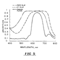
- FIG. 5 shows the computed absorption of a light blue and dark blue gel in the visible wavelength spectrum superimposed on the absorption shown for an energy filter according to the present invention.
- the present invention is directed to a system for extending the life of bluish, reddish, or greenish colored gels used in various optical assemblies or lighting apparatus, especially light fixtures adapted to image a high-intensity beam of colored light at a distant location.
- the present invention includes a filter/mirror coating that has a reflectance band falling in the same wavelength region as an absorption band for a colored gel such that burning or bleaching of the colored gel is significantly reduced.
- a dark green gel has an absorption curve that extends from 175 nm to 3300 nm in the UV, visible, and IR wavelength region, as shown in Fig. 1. Wavelengths from 175 - 400 nm are in the ultraviolet region (UV), from 400 - 700 nm are in the visible region, and 700+ are in the infrared region (IR).
- UV ultraviolet region
- IR infrared region
- Removing the IR light transmitted by the bulb of the lighting fixture does not entirely prevent the bleaching and burning of colored gels used in the lighting fixture.
- Most stage lights now have cold mirrors within the optical system to prevent IR light from being projected toward the stage and performers.
- An Optivex® UV filter commercially available from Bausch & Lomb Incorporated, Thin Film Technology Division (Rochester, NY) rejects all UV wavelengths from 175 - 400 nm. This filter was used in a typical spot light and the gels were still found to burn in the same fashion.
- the light fixture may employ a tungsten-halogen, arc, plasma, or other light source.
- a spot light employs a tungsten-halogen light bulb that puts out energy similar to a blackbody cavity at a temperature of 3200 K.
- Fig. 2 shows the normalized energy density spectrum for a 3200 K black body. Referring to Fig. 2, one can see that the majority of the energy within the visible spectrum, i.e., 400 to 700 nm, of a tungsten light bulb falls between 500 - 700 nm. If this curve is overlapped with the absorption curve for a greenish gel, for example, one can see that the gel has a high amount of absorption in the highest energy regions of the light bulb in the visible spectrum.
- FIG. 3 shows the computed absorption of greenish gel in the visible wavelength region for a dark-green gel and, for comparison, a yellow-green gel, superimposed on the spectrum shown in FIG. 2. It is evident that the high energy and gel absorption region is in the range of approximately 500 to 700 nm. When all of that visible energy emitted by the bulb is absorbed by the gel, the absorption levels cause the gel to heat up, bleach, and then burn.
- the present invention is applicable to sufficiently saturated colors meeting certain requirements for saturation (chroma).
- the term "sufficiently saturated color” is herein defined as a color having a spectrum in which the absorption is at least 90% or greater over a region of at least about 40 nm in the visible spectrum, preferably in which the absorption is at least 95% over a region of at least about 60 nm in the visible spectrum, more preferably in which the absorption is at least about 95% over a region of at least about 80 nm in the visible region.
- the dark green gel in Fig. 3 is a sufficiently saturated color
- the yellow-green gel is not sufficiently saturated for the present invention.
- the yellow-green gel has an absorption peak at 90% or above over a region of only about 30 nm.
- the present invention therefore utilizes a thin-film array that rejects the energy in the highest absorption regions before it hits the gel, thereby extending the life of the gel being used.
- a typical filter to reject that energy is a mirror or energy filter specifically built for the absorption regions of different color gels.
- Energy filters in general are commercially available from a variety of sources, including Bausch & Lomb Incorporated, Thin Film Technology Division (Rochester, NY); OCLI (Santa Rosa, CA); DSI (Santa Rosa, CA); and High-End Systems (TX).
- a protective filter for a bluish, greenish, or reddish gel could be designed and manufactured wherein the array of thin films is selected to reflect light in the visible light spectrum in a wavelength region between about 400 and 700 nm.
- the array of thin films should be designed such that a majority of the energy of the light incident on the array of thin films in the region between 600 and 700 nm is reflected by the array of thin films, preferably such that at least about 80 percent of the energy of the light incident on the array of thin films in the region between 630 and 750 nm is reflected by the array of thin films.
- region or “spectrum,” as used herein, are used interchangeably throughout this specification, to denote any continuous wavelength range of the electromagnetic spectrum spanned by two distinct wavelengths.
- FIG. 4 shows a computed design for an energy filter that could be used to extend the life of greenish gels.
- the reflection band of this filter falls within the absorption band of the greenish gel.
- the same or similar filter design could be used for a bluish gel, as shown in FIG. 5, which is a graph of the computed absorption of a sufficiently saturated light-blue gel and a sufficiently saturated dark-blue gel in the visible wavelength region superimposed on the absorption for an energy filter according to the present invention.
- the layer components of the thin-film multilayer will have refractive indices between 1.36 and 4.0 and will have thicknesses between 10 and 1000 nm (0.01 to 1 micron). These limits are dependent upon the desired result, and upon the refractive index of not only the lower index material, but also the refractive index of the higher index material.
- the lower index materials which are suitable for use in the present invention include, but are not limited to, MgF 2 , Al 2 O 3 , ThO 2 , ThF 4 , SiO 2 , NdF 3 , Na 3 AlF 6 (cryolite), NaF, MgO, LiF, LaF 3 , CeF 2 and AlF 3 .
- the higher index materials are formed from various dielectrics including, but not limited to, TiO 2 , Ti 2 O 3 and other Ti x O y derivatives, HfO 2 , CdS, CeO 2 , Ta 2 O 5 , ZnS, and ZrO 2 .
- the class of "higher refractive index" materials will have refractive indices in the range of 1.50 to 2.40 as deposited.
- the coatings will preferably be between 40 and 400 nm in thickness, although it is understood that the actual film thickness will be influenced by the refractive index of the material and the desired spectral characteristics of the reflector.
- the thickness of the layers can be, but are not necessarily limited to, a quarter wavelength in thickness of the wavelengths one wants to fully reflect.
- the thin-film materials can be deposited in a number of ways. Physical vapor deposition has been found to be the preferred method.
- a number of quarter-wave layers are successively coated on the surface of a substrate, so that layers formed of material having low refractive index alternate with layers formed of material having high refractive index.
- the number of quarter-wave layers (each having an optical thickness approximately equal to a desired quarter wavelength) coated on the substrate will depend on the desired optical properties of the filter for a particular colored gel.
- the number of layers can suitably vary from about six to about 50, preferably about 10 to 25.
- the invention in its broadest sense is not limited to filters having any specific number of layers.
- the layer immediately adjacent to the substrate may be a member of the subset of materials having low refractive index or may be a member of the subset having high refractive index.
- the substrate is glass
- the even layers are composed of silicon dioxide
- the odd layers are composed of titanium dioxide.
- the layers in each subset need not all have identical refractive index.
- each of the preferred embodiments of the invention can be determined using an iterative optimization technique in which the optical constants of the substrate and film materials are known and the desired reflectance spectrum is specified. The thickness of each layer is then found. To insure that the filter can be conveniently and economically manufactured in commercial quantities, each layer's thickness must be within a specified tolerance of optimum thickness such that any small variations in each layer's thickness will not significantly alter the filter's reflectance curve.
- Those of ordinary skill in the art will be familiar with, and capable of performing such an iterative optimization operation, as a matter of routine design. The operation will typically include the steps of choosing a merit function, and then minimizing the merit function utilizing an optimization routine, to determine the optimal set of design parameters. For example, U.S. Pat. No. 4,536,063 discusses the manner in which an optical coating design merit function may be chosen and then minimized, to generate a desired optical coating design.
- the substrate can be made from glass or any plastic which is thermally stable within the temperature cycles anticipated for the particular optical device being designed.
- plastic materials suggest themselves and without providing a complete list, these include polysulfones, polyetherimides, polyarylates, acrylics, polyesters, and polycarbonates. The actual choice of material may depend upon the light source, power, the use of the lamp, the cost and life of the lamp and other considerations.
- a glass or plastic substrate can be coated with the filter coating on one or both sides and inserted in the optical path of the spot light to block the light before it reaches the gel.
- the thin-film array comprising the energy filter may be coated directly onto the gel itself.
- the substrate may be flat or contoured, depending on the optical system involved.
- a contoured shape may be advantageous when the filter is situated in front of and in proximity to a lamp, in order to prevent reflected energy from reaching and adversely affecting the bulb in the lamp.
- the filters for extending the life of colored gels can be used in a variety of lighting apparatus, for example, those shown in U.S. Patents No. 5,446,637 and U.S. Patent No. 4,890,208; both hereby incorporated by reference in their entirety.
- Such lighting apparatuses typically have a concave or ellipsoid reflector having a base at one end and a mouth at the other end, the reflector being substantially circumferentially symmetrical about a longitudinal axis.
- the reflector reflects light emitted by the filaments of the lamp positioned within the reflector and forms a beam that is imaged to a predetermined location.
- light emitted by the filaments of the lamp are reflected by the reflector through a gate assembly, to one or more lenses, which form a generally collimated beam that is projected through one or more colored media and away from the lighting apparatus.
- guide means and a pivotal retainer for carrying one or more colored media in a media frame are positioned at the forward end of a generally cylindrical front barrel of the lighting apparatus.
- mirrors may be used to aim the beam in different directions.
- the colored media may be provided before, after, or between the lenses in an optical assembly.
- a color wheel or disc having a number of discrete colored filters may be used or several strips of colored film can be wound or unwound around a reel, wherein the films in combination yield a comprehensive range of colors and hues.
- the filter according to the present invention must be situated between the light source and the colored media.
- Conventional lighting apparatus can be readily adapted to suitably hold an energy filter according to the present invention in the optical path of a beam of light.
- a flat filter according to the present invention can be sandwiched on a colored sheet.
- a flat or contoured filter according to the present invention can be placed nearer the lamp.
- a shutter/pattern assembly or the like in the second focal region of the lamp reflector could be modified with slots to insert a filter into the path of the beam being projected. Conventionally, such slots are sometimes provided to insert a pattern template.
- the bandpass filter was made to face toward a tungsten filament of a bulb within a "Source 4"® spot light, manufactured by ETC, Inc. (Middleton, WI) so that the energy was not reflected into the glass sample.
- the back side of the samples had an antireflection coating that faced the gel.
- the average transmission over the 400 - 600 nm region was approximately 93%.
- Test samples 3 and 14 with bluish or greenish gels in series were also measured on a spectrophotometer and their x/y color coordinates and light level difference calculated versus a 3200 K source. As shown in Table 2 below, the filters did not adversely affect the color produced by the gels.
Landscapes
- Physics & Mathematics (AREA)
- General Physics & Mathematics (AREA)
- Optics & Photonics (AREA)
- Engineering & Computer Science (AREA)
- General Engineering & Computer Science (AREA)
- Spectroscopy & Molecular Physics (AREA)
- Optical Filters (AREA)
- Colloid Chemistry (AREA)
- Compositions Of Macromolecular Compounds (AREA)
- Processes Of Treating Macromolecular Substances (AREA)
Claims (12)
- Un assemblage optique avec une lampe configurée pour obtenir un faisceau de lumière colorée en un emplacement éloigné, comprenant:(a) une source de lumière ayant des composantes dont les longueurs d'onde sont dans l'UV, le visible et l'IR;(b) un gel coloré suffisamment saturé tirant sur le bleu, le vert ou le rouge;(c) et, situé entre la source de lumière et le gel coloré, un filtre comprenant un ensemble de films fins de diélectriques ayant, en alternance, des indices de réfraction élévés et des indices de réfraction faibles, déposé sur la surface d'un substrat, ledit ensemble étant choisi de sorte qu'un spectre de lumière visible souhaité est réfléchi à partir dudit filtre de sorte que le filtre a une bande de réflectance qui tombe dans la même région des longueurs d'onde du spectre de lumière visible qu'une bande d'absorption pour le gel coloré.
- L'assemblage optique de la revendication 1, dans lequel le substrat est le gel coloré lui-même.
- L'assemblage optique de la revendication 1, dans lequel la lampe a un ou plusieurs filaments et dans lequel la lampe est située à l'intérieur de l'ouverture concave d'un réflecteur ellipsoïdal concave.
- L'assemblage optique de la revendication 1, dans lequel le substrat est un matériau transparent en plastique ou en verre qui est recouvert de l'ensemble de films fins sur un ou deux de ses côtés.
- L'assemblage optique de la revendication 1, dans lequel l'ensemble de films fins est choisi pour réfléchir la lumière dans le spectre de lumière visible dans la région des longueurs d'onde comprise entre 500 et 800 nm.
- L'assemblage optique de la revendication 5, dans lequel l'ensemble de films fins est conçu de sorte qu'une majorité de l'énergie de la lumière incidente sur l'ensemble de films fins dans la région comprise entre 600 et 700 nm est réfléchie par l'ensemble de films fins.
- L'assemblage optique de la revendication 6, dans lequel l'ensemble de films fins est conçu de sorte qu'au moins 80 % de l'énergie de la lumière incidente sur l'ensemble de films fins dans la région comprise entre 630 et 750 nm est réfléchie par l'ensemble de films fins.
- L'assemblage optique de la revendication 1, dans lequel ledit substrat est fabriqué à partir d'un matériau plastique choisi parmi le groupe des polymères polycarbonate, polysulfone, polyacrylate, polyacrylique et polyétherimide.
- L'assemblage optique de la revendication 1, dans lequel ledit ensemble de films fins de diélectriques ayant des indices de réfraction élévés et faibles en alternance du revêtement optique, sont des couches alternées d'un matériau choisi parmi le groupe consistant en TiO2 et SiO2, ZnS et MgF2, TiO2 et MgF2 et ZrO2 et SiO2.
- Un procédé pour prolonger la vie utile d'un gel coloré suffisamment saturé tirant sur le bleu, le vert ou le rouge, comprenant le placement d'un filtre dans le trajet optique d'un faisceau de lumière pour bloquer sélectivement un spectre souhaité de lumière visible avant qu'il n'atteigne le gel coloré, le filtre comprenant un ensemble de films déposé sur un ou deux côtés d'un substrat en verre ou en plastique.
- Un article comprenant un matériau de type gel coloré suffisamment saturé tirant sur le bleu, le vert ou le rouge, sur lequel est déposé un ensemble de films fins de diélectriques ayant en alternance des indices de réfraction élevés et des indices de réfraction faibles, lequel ensemble est adapté pour réfléchir un spectre souhaité de lumière visible tombant dans la même région des longueurs d'onde du spectre de lumière visible qu'une bande d'absorption pour le gel coloré.
- L'article de la revendication 11, dans lequel le matériau de type gel coloré est sous la forme d'une feuille.
Applications Claiming Priority (3)
| Application Number | Priority Date | Filing Date | Title |
|---|---|---|---|
| US2066596P | 1996-06-28 | 1996-06-28 | |
| US20665P | 1996-06-28 | ||
| PCT/US1997/011223 WO1998000669A1 (fr) | 1996-06-28 | 1997-06-26 | Systeme permettant de prolonger la vie utile de gels colores |
Publications (2)
| Publication Number | Publication Date |
|---|---|
| EP0922183A1 EP0922183A1 (fr) | 1999-06-16 |
| EP0922183B1 true EP0922183B1 (fr) | 2000-09-13 |
Family
ID=21799885
Family Applications (1)
| Application Number | Title | Priority Date | Filing Date |
|---|---|---|---|
| EP97931461A Expired - Lifetime EP0922183B1 (fr) | 1996-06-28 | 1997-06-26 | Systeme permettant de prolonger la vie utile de gels colores |
Country Status (6)
| Country | Link |
|---|---|
| US (1) | US6004009A (fr) |
| EP (1) | EP0922183B1 (fr) |
| AT (1) | ATE196354T1 (fr) |
| AU (1) | AU3508597A (fr) |
| DE (1) | DE69703116T2 (fr) |
| WO (1) | WO1998000669A1 (fr) |
Families Citing this family (2)
| Publication number | Priority date | Publication date | Assignee | Title |
|---|---|---|---|---|
| US6897609B2 (en) * | 2001-03-30 | 2005-05-24 | Advanced Lighting Technologies, Inc. | Plasma lamp and method |
| US20050057830A1 (en) * | 2003-09-13 | 2005-03-17 | Creative Film Corp. | Laminated color light filter |
Family Cites Families (11)
| Publication number | Priority date | Publication date | Assignee | Title |
|---|---|---|---|---|
| JPS5694309A (en) * | 1979-12-27 | 1981-07-30 | Fuji Photo Film Co Ltd | Multicolor optical filter and its production |
| US4380794A (en) * | 1981-06-15 | 1983-04-19 | Sybron Corporation | Surgical lamp characterized by having an improved reflector |
| US4536063A (en) * | 1982-12-14 | 1985-08-20 | Rockwell International Corporation | Transmissive phase retarder |
| US4705356A (en) * | 1984-07-13 | 1987-11-10 | Optical Coating Laboratory, Inc. | Thin film optical variable article having substantial color shift with angle and method |
| US4890208A (en) * | 1986-09-19 | 1989-12-26 | Lehigh University | Stage lighting apparatus |
| AU6885391A (en) * | 1989-11-24 | 1991-06-26 | Innovare Limited | A display device |
| US5169229A (en) * | 1990-01-09 | 1992-12-08 | Bausch & Lomb Incorporated | Enhanced metal filter/mirror coatings for use on engineering plastics |
| US5339198A (en) * | 1992-10-16 | 1994-08-16 | The Dow Chemical Company | All-polymeric cold mirror |
| US5345371A (en) * | 1992-11-05 | 1994-09-06 | Cunningham David W | Lighting fixture |
| US5694240A (en) * | 1994-06-24 | 1997-12-02 | Bausch & Lomb Incorporated | Multilayer anti-reflective and ultraviolet blocking coating for sunglasses |
| US5646781A (en) * | 1995-05-15 | 1997-07-08 | Omega Optical, Inc. | Optical filters for forming enhanced images |
-
1997
- 1997-06-26 US US08/883,110 patent/US6004009A/en not_active Expired - Lifetime
- 1997-06-26 AU AU35085/97A patent/AU3508597A/en not_active Abandoned
- 1997-06-26 DE DE69703116T patent/DE69703116T2/de not_active Expired - Lifetime
- 1997-06-26 AT AT97931461T patent/ATE196354T1/de not_active IP Right Cessation
- 1997-06-26 EP EP97931461A patent/EP0922183B1/fr not_active Expired - Lifetime
- 1997-06-26 WO PCT/US1997/011223 patent/WO1998000669A1/fr not_active Ceased
Also Published As
| Publication number | Publication date |
|---|---|
| DE69703116D1 (de) | 2000-10-19 |
| EP0922183A1 (fr) | 1999-06-16 |
| DE69703116T2 (de) | 2001-05-10 |
| WO1998000669A1 (fr) | 1998-01-08 |
| ATE196354T1 (de) | 2000-09-15 |
| AU3508597A (en) | 1998-01-21 |
| US6004009A (en) | 1999-12-21 |
Similar Documents
| Publication | Publication Date | Title |
|---|---|---|
| US4839553A (en) | Reflector lamp having complementary dichroic filters on the reflector and lens for emitting colored light | |
| US5177396A (en) | Mirror with dichroic coating lamp housing | |
| US7535636B2 (en) | Selective reflecting | |
| US4649462A (en) | Viewing angle color sensitive lighting accessory | |
| CA2480648A1 (fr) | Miroir dichroique et unite d'affichage de type projecteur | |
| JPH03122903A (ja) | カラー・ホイール | |
| US5169229A (en) | Enhanced metal filter/mirror coatings for use on engineering plastics | |
| US4161015A (en) | Luminaire using a multilayer interference mirror | |
| US4726654A (en) | Multi-layered anti-reflection coating | |
| US4870318A (en) | Projector lamp emitting color light | |
| JPH0439854A (ja) | 照明装置 | |
| US5285362A (en) | Discharge lamp having interference filter | |
| US6004009A (en) | System for extending the useful life of colored gels | |
| US5786937A (en) | Thin-film color-selective beam splitter and method of fabricating the same | |
| US3528725A (en) | Color temperature correction light transmitting filter | |
| WO2001097244A2 (fr) | Lampe lumiere du jour amelioree | |
| US4218134A (en) | Optical system for copier | |
| HU180333B (en) | Reflecting mirror for decreasing the luminous rays being in the infrared region | |
| JPH08106059A (ja) | 内視鏡用光源光学系 | |
| EP0786799B1 (fr) | Lampe à incandescence avec réflecteur à spectre d'émission semblable à celui du soleil | |
| Schroeder et al. | A commercial cold reflector | |
| JPH0282403A (ja) | 照明器具 | |
| Parham et al. | Durable Cold-Mirror Coatings for Display Lighting | |
| JPS6275402A (ja) | 投光型多層膜反射鏡 | |
| JPS612201A (ja) | 信号灯器 |
Legal Events
| Date | Code | Title | Description |
|---|---|---|---|
| PUAI | Public reference made under article 153(3) epc to a published international application that has entered the european phase |
Free format text: ORIGINAL CODE: 0009012 |
|
| 17P | Request for examination filed |
Effective date: 19990409 |
|
| AK | Designated contracting states |
Kind code of ref document: A1 Designated state(s): AT BE CH DE DK ES FI FR GB GR IE IT LI LU MC NL PT SE |
|
| GRAG | Despatch of communication of intention to grant |
Free format text: ORIGINAL CODE: EPIDOS AGRA |
|
| 17Q | First examination report despatched |
Effective date: 19991119 |
|
| GRAG | Despatch of communication of intention to grant |
Free format text: ORIGINAL CODE: EPIDOS AGRA |
|
| GRAH | Despatch of communication of intention to grant a patent |
Free format text: ORIGINAL CODE: EPIDOS IGRA |
|
| RIC1 | Information provided on ipc code assigned before grant |
Free format text: 7F 21V 7/22 A, 7G 02B 5/26 B |
|
| GRAH | Despatch of communication of intention to grant a patent |
Free format text: ORIGINAL CODE: EPIDOS IGRA |
|
| GRAA | (expected) grant |
Free format text: ORIGINAL CODE: 0009210 |
|
| AK | Designated contracting states |
Kind code of ref document: B1 Designated state(s): AT BE CH DE DK ES FI FR GB GR IE IT LI LU MC NL PT SE |
|
| PG25 | Lapsed in a contracting state [announced via postgrant information from national office to epo] |
Ref country code: NL Free format text: LAPSE BECAUSE OF FAILURE TO SUBMIT A TRANSLATION OF THE DESCRIPTION OR TO PAY THE FEE WITHIN THE PRESCRIBED TIME-LIMIT Effective date: 20000913 Ref country code: LI Free format text: LAPSE BECAUSE OF FAILURE TO SUBMIT A TRANSLATION OF THE DESCRIPTION OR TO PAY THE FEE WITHIN THE PRESCRIBED TIME-LIMIT Effective date: 20000913 Ref country code: IT Free format text: LAPSE BECAUSE OF FAILURE TO SUBMIT A TRANSLATION OF THE DESCRIPTION OR TO PAY THE FEE WITHIN THE PRE;WARNING: LAPSES OF ITALIAN PATENTS WITH EFFECTIVE DATE BEFORE 2007 MAY HAVE OCCURRED AT ANY TIME BEFORE 2007. THE CORRECT EFFECTIVE DATE MAY BE DIFFERENT FROM THE ONE RECORDED.SCRIBED TIME-LIMIT Effective date: 20000913 Ref country code: FI Free format text: LAPSE BECAUSE OF FAILURE TO SUBMIT A TRANSLATION OF THE DESCRIPTION OR TO PAY THE FEE WITHIN THE PRESCRIBED TIME-LIMIT Effective date: 20000913 Ref country code: ES Free format text: THE PATENT HAS BEEN ANNULLED BY A DECISION OF A NATIONAL AUTHORITY Effective date: 20000913 Ref country code: CH Free format text: LAPSE BECAUSE OF FAILURE TO SUBMIT A TRANSLATION OF THE DESCRIPTION OR TO PAY THE FEE WITHIN THE PRESCRIBED TIME-LIMIT Effective date: 20000913 Ref country code: BE Free format text: LAPSE BECAUSE OF FAILURE TO SUBMIT A TRANSLATION OF THE DESCRIPTION OR TO PAY THE FEE WITHIN THE PRESCRIBED TIME-LIMIT Effective date: 20000913 Ref country code: AT Free format text: LAPSE BECAUSE OF FAILURE TO SUBMIT A TRANSLATION OF THE DESCRIPTION OR TO PAY THE FEE WITHIN THE PRESCRIBED TIME-LIMIT Effective date: 20000913 |
|
| REF | Corresponds to: |
Ref document number: 196354 Country of ref document: AT Date of ref document: 20000915 Kind code of ref document: T |
|
| REG | Reference to a national code |
Ref country code: CH Ref legal event code: EP |
|
| REF | Corresponds to: |
Ref document number: 69703116 Country of ref document: DE Date of ref document: 20001019 |
|
| REG | Reference to a national code |
Ref country code: IE Ref legal event code: FG4D |
|
| PG25 | Lapsed in a contracting state [announced via postgrant information from national office to epo] |
Ref country code: SE Free format text: LAPSE BECAUSE OF FAILURE TO SUBMIT A TRANSLATION OF THE DESCRIPTION OR TO PAY THE FEE WITHIN THE PRESCRIBED TIME-LIMIT Effective date: 20001213 Ref country code: PT Free format text: LAPSE BECAUSE OF FAILURE TO SUBMIT A TRANSLATION OF THE DESCRIPTION OR TO PAY THE FEE WITHIN THE PRESCRIBED TIME-LIMIT Effective date: 20001213 Ref country code: DK Free format text: LAPSE BECAUSE OF FAILURE TO SUBMIT A TRANSLATION OF THE DESCRIPTION OR TO PAY THE FEE WITHIN THE PRESCRIBED TIME-LIMIT Effective date: 20001213 |
|
| PG25 | Lapsed in a contracting state [announced via postgrant information from national office to epo] |
Ref country code: GR Free format text: LAPSE BECAUSE OF FAILURE TO SUBMIT A TRANSLATION OF THE DESCRIPTION OR TO PAY THE FEE WITHIN THE PRESCRIBED TIME-LIMIT Effective date: 20001215 |
|
| ET | Fr: translation filed | ||
| NLV1 | Nl: lapsed or annulled due to failure to fulfill the requirements of art. 29p and 29m of the patents act | ||
| REG | Reference to a national code |
Ref country code: CH Ref legal event code: PL |
|
| PG25 | Lapsed in a contracting state [announced via postgrant information from national office to epo] |
Ref country code: LU Free format text: LAPSE BECAUSE OF NON-PAYMENT OF DUE FEES Effective date: 20010626 |
|
| PG25 | Lapsed in a contracting state [announced via postgrant information from national office to epo] |
Ref country code: MC Free format text: LAPSE BECAUSE OF NON-PAYMENT OF DUE FEES Effective date: 20010630 |
|
| PLBE | No opposition filed within time limit |
Free format text: ORIGINAL CODE: 0009261 |
|
| STAA | Information on the status of an ep patent application or granted ep patent |
Free format text: STATUS: NO OPPOSITION FILED WITHIN TIME LIMIT |
|
| 26N | No opposition filed | ||
| REG | Reference to a national code |
Ref country code: GB Ref legal event code: IF02 |
|
| PGFP | Annual fee paid to national office [announced via postgrant information from national office to epo] |
Ref country code: IE Payment date: 20050719 Year of fee payment: 9 |
|
| PG25 | Lapsed in a contracting state [announced via postgrant information from national office to epo] |
Ref country code: IE Free format text: LAPSE BECAUSE OF NON-PAYMENT OF DUE FEES Effective date: 20060626 |
|
| REG | Reference to a national code |
Ref country code: IE Ref legal event code: MM4A |
|
| PGFP | Annual fee paid to national office [announced via postgrant information from national office to epo] |
Ref country code: FR Payment date: 20110629 Year of fee payment: 15 |
|
| PGFP | Annual fee paid to national office [announced via postgrant information from national office to epo] |
Ref country code: GB Payment date: 20110628 Year of fee payment: 15 |
|
| PGFP | Annual fee paid to national office [announced via postgrant information from national office to epo] |
Ref country code: DE Payment date: 20110629 Year of fee payment: 15 |
|
| GBPC | Gb: european patent ceased through non-payment of renewal fee |
Effective date: 20120626 |
|
| REG | Reference to a national code |
Ref country code: FR Ref legal event code: ST Effective date: 20130228 |
|
| REG | Reference to a national code |
Ref country code: DE Ref legal event code: R119 Ref document number: 69703116 Country of ref document: DE Effective date: 20130101 |
|
| PG25 | Lapsed in a contracting state [announced via postgrant information from national office to epo] |
Ref country code: GB Free format text: LAPSE BECAUSE OF NON-PAYMENT OF DUE FEES Effective date: 20120626 Ref country code: FR Free format text: LAPSE BECAUSE OF NON-PAYMENT OF DUE FEES Effective date: 20120702 Ref country code: DE Free format text: LAPSE BECAUSE OF NON-PAYMENT OF DUE FEES Effective date: 20130101 |