EP0922411A2 - Surface pour supporter un bras - Google Patents
Surface pour supporter un bras Download PDFInfo
- Publication number
- EP0922411A2 EP0922411A2 EP98123448A EP98123448A EP0922411A2 EP 0922411 A2 EP0922411 A2 EP 0922411A2 EP 98123448 A EP98123448 A EP 98123448A EP 98123448 A EP98123448 A EP 98123448A EP 0922411 A2 EP0922411 A2 EP 0922411A2
- Authority
- EP
- European Patent Office
- Prior art keywords
- base
- movable base
- movable
- boss
- fixed
- Prior art date
- Legal status (The legal status is an assumption and is not a legal conclusion. Google has not performed a legal analysis and makes no representation as to the accuracy of the status listed.)
- Withdrawn
Links
Images



Classifications
-
- A—HUMAN NECESSITIES
- A47—FURNITURE; DOMESTIC ARTICLES OR APPLIANCES; COFFEE MILLS; SPICE MILLS; SUCTION CLEANERS IN GENERAL
- A47B—TABLES; DESKS; OFFICE FURNITURE; CABINETS; DRAWERS; GENERAL DETAILS OF FURNITURE
- A47B21/00—Tables or desks for office equipment, e.g. typewriters, keyboards
- A47B21/03—Tables or desks for office equipment, e.g. typewriters, keyboards with substantially horizontally extensible or adjustable parts other than drawers, e.g. leaves
- A47B21/0371—Platforms for supporting wrists
Definitions
- the present invention relates to a supporting means of arm for assisting a movement of arm to facilitate an operation of mouse for personal computer and the like.
- a personal computer mouse In general, the operation of a personal computer mouse is carried out such that the mouse is moved on a sponge or rubber mat placed on a desk under a condition that an arm is supported by the desk or is floated above the desk. Further a movable base, which is movable in a longitudinal or lateral direction on a plane, may be used so that the mouse is operated with the arm placed on this movable base.
- FIG. 9 A conventional art of such movable base is shown in Fig. 9, which can be freely moved on a plane.
- Rails 100 are first provided in parallel to each other, and movable rails 200 are provided to these rails 100 so as to be movable in a direction indicated by an arrow (a).
- a movable base 300 is provided to these movable rails 200 so as to be movable in a direction indicated by an arrow (b).
- the relative movement of the movable rails 200 in the arrow (a) direction and the relative movement of the movable base 300 in the arrow (b) direction cooperatively causes a horizontal movement of the movable base 300 on the plane (This cooperative movement is referred to as the horizontal movement).
- the practical utility lacks since the movable range of the movable base 300 on the plane becomes narrower.
- the length of the rails 100 and the movable rails 200 are set long relative to the movable base 300 as shown in the Figure, the length of the rails is longer than the length of the arm from the elbow to the hand holding the mouse, and hinders the operation of the mouse. Consequently, a problem in working efficiency, is caused.
- the present invention is not limited to the mouse for personal computer, and may be used in other application relating to a work to be done, on a desk while laying an arm thereon such as drafting a drawing, writing a note and the like.
- An object of the present invention is to provide an arm supporting base, in which its size is compact and it is possible to move horizontally and rotationally to prevent an occurrence of fatigue of arm operating a mouse thereby to increase a working efficiency.
- the arm supporting base comprising a fixed base, at a center portion of which a circular hole is formed, a movable base disposed above the fixed base and on the bottom of which a boss being protruded through the circular hole is provided, at least three ball bearings provided on the fixed base around the hole, and a back plate larger in diameter than the hole to be fixed to the protruded tip end of the boss beneath the circular hole.
- two circular boles in which the movement of the movable base is allowed are formed at right and left portions of the elliptic fixed base, a plurality of ball bearings are provided around the respective circular holes, the elliptic movable base is put on the ball bearings and the horizontal movement of the movable base to the fixed base may be realized within the area of the circular holes.
- an arm supporting base is arranged in such a manner, as shown in Fig. 2, that a movable base 4 is supported on a fixed base 5 through balls 7 interposed between the movable base 4 and the fixed base 5, a boss 8 is protruded at a center of the movable base 4 through a circular hole 9 larger in diameter than the one of the boss 8 is opened in the fixed base 5, and a back plate 10 larger in diameter than the hole 9 is fixed to the tip end of the boss 8. Further, a height H 1 of the boss 8, as shown in Fig. 3, is set so as to form a slight clearance between the back plate 10 fixed to the boss 8 and a back surface of the fixed base 5.
- the ball bearings are provided on the fixed base 5, the movable base 4 is put on these balls 7, and then a back plate 10 is fixed to the tip end of the boss 8 with a screw 15, so that the movable base 4 is prevented from being removed from the fixed base 5.
- a height H 2 (see Fig. 3) of a flange of the movable base 4 and a diameter of each of the balls 7 are determined in such a manner as a slight clearance is formed between a lower edge 17 (see Fig. 3) of the flange of the movable base 4 and an upper surface of the fixed base 5 in this condition.
- the sectional shape of the movable base 4 is of a dish having a flange 18 of the height H 2 so that the movable base 4 hides the balls 7 in such a manner that the balls 7 are prevented from being viewed externally to thereby improve the external appearance, and the movable base 4 moves rotatably more on the balls 7 to thereby make the parallel and rotational movements on a plane freely within the range of the circular hole 9.
- the upper surface 19 is recessed, so that a pad 12 (see Fig. 2) can be attached thereto.
- the boss 8 is formed at a center of the movable base 4, and a threaded hole 801 is formed in this boss 8 (see Fig. 3).
- the sectional shape of the fixed base 5 is of a dish having a flange 21 of the height H 4 so as to define a space in which the back plate 10 is movable.
- the circular hole 9 having the diameter D 2 larger than the diameter of the boss 8 is provided at a center of the fixed base 5, and a plurality of the ball bearings are disposed around this circular hole 9. If the inner side of the flange 18 is brought into contact with the ball bearings during the movement of the movable base 4 placed on the balls 7, the smooth movement of the movable base 4 owing to the balls 7 is lessened.
- the diameter of the boss 8, the diameter D 2 of the hole 9 and the pitch circle diameter P 1 of the ball bearings are so determined as to prevent the inner circumferential surface of the flange 18 from being contacted with the ball bearings. That is to say, the inner circumferential surface of the flange 18 is not contacted with the ball bearings under a condition that the boss 8 is contacted with the inner edge of the circular hole 9 during the movement of the movable base 4.
- each of receptacles 13 of the ball bearings is slightly larger than the diameter of the ball 7, and the depth H 3 thereof is equal to or slightly larger than the radius of the ball 7.
- the diameter D 1 of the back plate 10 is larger than the diameter D 2 of the circular hole 9 to prevent the back plate 10 from being pulled out through the circular hole 9, wherever the movable base 4 is located.
- the back plate 10 is fixed to the tip end of the boss 8 with the screw 15 as shown in Fig. 2.
- the movable base 4 and the fixed base 5 are unified together.
- the inclination of the movable base 4 can be avoided in the case where the boss 8 is contacted with the inner edge of the circular hole 9, i.e., in the case where the movable base 4 is most offset from the fixed base 5.
- the back plate 10 is also designed to avoid the inclination of the movable base 4.
- the back plate 10 is formed at its center with a screw passing hole 20.
- a boss 14 having the same height as the height H 4 of the flange 21 is provided on the back surface of the fixed base 5.
- This boss 14 is positioned so as not to be contacted with the outer periphery of the back plate 10 under a condition that the boss 8 shown in Fig. 3 is contacted with the inner edge of the circular hole 9. This permits the free movement of the boss 8 within the circular hole 9.
- the boss 14 is provided with a threaded hole 141.
- a bottom plate 6 is provided with a screw passing hole 601 passing therethrough, and a flange 602 is formed, which is fitted into the inner edge of the flange 21 of the fixed base 5.
- the balls 7 are first fallen into the ball receptacle 13 to make the ball bearings and then covered by the movable base 4 placed thereon in such a manner as the boss 8 is protruded through the circular hole 9.
- the back plate 10 is fixed to the tip end of the boss 8 with the screw 15 under this condition.
- the bottom plate 6 is fixed to the bosses 14 with the screws 16 while being contacted with the fixed base 5 through the ball bearings.
- the movable base 4 moves as follows: That is, since the movable base 4 is supported on the fixed base 5 with the balls 7 interposed between the fixed base 5 and the movable base 4, the movable base 4 may move horizontally in parallel with the fixed base 5 in association with the horizontal movement of the arm. If the hand makes such movement as to operate the mouse right and left, the movable base 4 is free responded to the mouse operation. In association with the motion of the hand, the movable base 4 can make both the horizontal and rotational movements on the fixed base 5.
- the boss 8 is protruded at the center of the movable base 4 through the circular hole 9 of the fixed base 5 larger in diameter than the boss 8, and the boss 8 is located within this circular hole 9.
- This arrangement permits the boss 8 to freely move within the circular hole 9 provided in the fixed plate 5 without restriction against the above-noted movements of the movable base 4, as well as delimits the movable range of the boss 8 to prevent the movable base 4 from being pulled out from the fixed base 5.
- the back plate 10 larger in diameter than this circular hole 9 is fixed to the boss 8, and the height H 1 (see Fig. 3) of the boss 8 is set so that a slight clearance is formed between the back plate 10 fixed to this boss 8 and the back surface 501 (see Fig. 5) of the fixed base 5. This can permit the movement of the movable base 4 while associating the fixed base 5 and the movable base 4 by the back plate 10.
- the ball bearings are interposed between the movable base 4 and the fixed base 5, the boss 8 provided on the movable base 4 is permitted to freely move within the circular hole 9 opened in the fixed base 5, the movable range of the movable base 4 is delimited without restricting the smooth movement of the movable base 4, and the movable base 4 and the fixed base 5 are unified together by the back plate 10. Therefore, the balls 7, the boss 8, the circular hole 9 and the back plate 10 can be accommodated in the inside of the movable base 4 and the fixed base 5, and the movable range of the movable base 4 can be set largely while making the entire size compact.
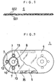
- the arm supporting base 1 comprises circular boles 9 in which the movement of the movable base 4 is allowed are formed at right and left portions of the elliptic fixed base 5, a plurality of ball bearings provided around the respective circular holes 9 and the elliptic movable base 4 put on the ball bearings.
- the numeral sign 35 indicates a fixing-hole for fixing the arm supporting base 1 to the desk or the like.
- Fig. 8 shows how to use a use example of the present invention in which a supporting base fitting recess 24 for fittingly mounting the arm supporting base 26 is provided in an end of a plate-like mat base 23, and a mat holding recess 25 for holding a mouse mat 22 is provided adjacent to the supporting base fitting recess 24.
- the hole is provided in the fixed base, a plurality of the ball hearings are provided around the circular hole, and the movable base is put on the balls received in the ball receptacles, so that the movable base is supported to make the horizontal movement on the plane with respect to the fixed base as well as to make the own rotation of the movable base.
- the boss is protruded at the center of the movable base through the circular hole 9, the back plate larger in diameter than the circular hole is fixed to the boss, the height of the boss is set so as to form a slight clearance between the back plate fixed to the boss and the back surface of the fixed base, and the boss is permitted to move within the circular hole, so that the movable range of the movable base is delimited without restricting the movement of the movable base, and the fixed base and the movable base are unified together by the back plate.
- the mouse operation can be facilitated with the arm placed on the movable base to prevent an occurrence of the fatigue of the arm and enhance the working efficiency.
- the arm supporting base comprises circular holes in which the movement of the movable base is allowed are formed at right and left portions of the elliptic fixed base, a plurality of ball bearings provided around the respective holes and the elliptic movable base put on the ball bearings. Since a plurality of ball bearings are disposed at right and left portions of the fixed base, the load of arm operating the mouse is dispersed at each bearing. Therefore, the more efficient movement of the arm operating the mouse may be realized.
Landscapes
- Position Input By Displaying (AREA)
- Input From Keyboards Or The Like (AREA)
Applications Claiming Priority (2)
| Application Number | Priority Date | Filing Date | Title |
|---|---|---|---|
| JP34263497 | 1997-12-12 | ||
| JP34263497 | 1997-12-12 |
Publications (2)
| Publication Number | Publication Date |
|---|---|
| EP0922411A2 true EP0922411A2 (fr) | 1999-06-16 |
| EP0922411A3 EP0922411A3 (fr) | 2002-01-16 |
Family
ID=18355297
Family Applications (1)
| Application Number | Title | Priority Date | Filing Date |
|---|---|---|---|
| EP98123448A Withdrawn EP0922411A3 (fr) | 1997-12-12 | 1998-12-11 | Surface pour supporter un bras |
Country Status (2)
| Country | Link |
|---|---|
| US (1) | US6102345A (fr) |
| EP (1) | EP0922411A3 (fr) |
Families Citing this family (5)
| Publication number | Priority date | Publication date | Assignee | Title |
|---|---|---|---|---|
| CN1121001C (zh) * | 1998-12-14 | 2003-09-10 | 卡路事务器株式会社 | 臂垫 |
| US20070256606A1 (en) * | 2006-05-02 | 2007-11-08 | Ivey Edward C | Adjustable tray for vehicle |
| USD697510S1 (en) * | 2011-03-23 | 2014-01-14 | Brother Industries, Ltd. | Scanner with projector |
| US9186542B2 (en) * | 2014-01-29 | 2015-11-17 | Yu Chen SHEN | Twisting exerciser device |
| USD855442S1 (en) * | 2015-10-30 | 2019-08-06 | Lg Electronics Inc. | Bracket for TV receiver |
Family Cites Families (14)
| Publication number | Priority date | Publication date | Assignee | Title |
|---|---|---|---|---|
| US988893A (en) * | 1910-09-24 | 1911-04-04 | Joseph Packewitz | Hand-rest. |
| US2307396A (en) * | 1940-02-15 | 1943-01-05 | Karl J Draxler | Sliding table top construction |
| US4117627A (en) * | 1977-06-03 | 1978-10-03 | Slingerland Jr Henry H | Rotatable stand |
| DE3246835A1 (de) * | 1982-12-17 | 1984-06-20 | thermohauser Erwin Busch GmbH, 7336 Uhingen | Drehbare tortenplatte |
| US4708408A (en) * | 1986-09-09 | 1987-11-24 | Ronnie Kennon | Home entertainment accessory organizer |
| US5265835A (en) * | 1992-04-13 | 1993-11-30 | Nash A Richard | Moveable forearm support |
| US5479867A (en) * | 1993-10-12 | 1996-01-02 | Blevins; Bruce D. | Rotary table |
| US5507458A (en) * | 1994-11-10 | 1996-04-16 | Fellowes Manufacturing Company | Height and tilt adjustable wrist rest |
| US5826842A (en) * | 1995-01-13 | 1998-10-27 | Or Computer Keyboards Ltd. | Ergonomic computer mouse workstation |
| US5657956A (en) * | 1995-08-14 | 1997-08-19 | Idea Development, Engineering And Service, Inc. | Thrust bearing and use of same with apparatus for reducing repetitive stress injury |
| US5765796A (en) * | 1995-10-05 | 1998-06-16 | Lanus; Alfred | Rotatable holder for kitchen appliances |
| US5743499A (en) * | 1997-01-07 | 1998-04-28 | Wang; Te-Ming | Arm support for computer operator |
| DE29721510U1 (de) * | 1997-12-05 | 1998-02-19 | Micro Meilon Co | Unterlage für eine Computermaus (Mousepad) |
| US5927663A (en) * | 1998-08-03 | 1999-07-27 | Tseng; Hui-Min | Table mount hand and arm support for operating a mouse |
-
1998
- 1998-12-08 US US09/207,463 patent/US6102345A/en not_active Expired - Fee Related
- 1998-12-11 EP EP98123448A patent/EP0922411A3/fr not_active Withdrawn
Also Published As
| Publication number | Publication date |
|---|---|
| US6102345A (en) | 2000-08-15 |
| EP0922411A3 (fr) | 2002-01-16 |
Similar Documents
| Publication | Publication Date | Title |
|---|---|---|
| US5228791A (en) | Bifurcated keyboard arrangement | |
| JP3833779B2 (ja) | 免震装置 | |
| US20030056322A1 (en) | Hinge device | |
| JP2002149078A (ja) | ディスプレイの支持装置 | |
| WO2000073024A2 (fr) | Montage orientable pour positionnement de dispositifs electroniques | |
| US6102345A (en) | Arm supporting base | |
| JPS61133837U (fr) | ||
| US5393150A (en) | Bifurcated keyboard arrangement | |
| US6328267B1 (en) | Arm support and pad for mouse using the same | |
| CN1360167A (zh) | 三轴向枢轴结构 | |
| KR19980014268U (ko) | 컴퓨터 마우스용 팔받침대 | |
| CN214156557U (zh) | 一种适用于教室的台式工作站 | |
| JPS6361036U (fr) | ||
| CN222911184U (zh) | 一种笔记本电脑支架 | |
| JPS5894016U (ja) | 回転置台 | |
| JPS6234342Y2 (fr) | ||
| JPS6033685U (ja) | 傾角ステージ | |
| JP3049979U (ja) | Pcリフター | |
| CN214248989U (zh) | 一种用于平板电脑的升降装置 | |
| JPH0715197Y2 (ja) | チルト・スイ−ベル機構 | |
| JP3069255U (ja) | ア―ムサポ―ト | |
| JPH0659919U (ja) | ノート型パソコンの底部構造 | |
| CN112860075A (zh) | 一种倾角可调且便于收纳的计算机键盘支撑结构 | |
| JPS6116361U (ja) | 重量物転倒回転装置 | |
| JPS589052U (ja) | 回転機の軸受装置 |
Legal Events
| Date | Code | Title | Description |
|---|---|---|---|
| PUAI | Public reference made under article 153(3) epc to a published international application that has entered the european phase |
Free format text: ORIGINAL CODE: 0009012 |
|
| AK | Designated contracting states |
Kind code of ref document: A2 Designated state(s): AT BE CH CY DE DK ES FI FR GB GR IE IT LI LU MC NL PT SE |
|
| AX | Request for extension of the european patent |
Free format text: AL;LT;LV;MK;RO;SI |
|
| PUAL | Search report despatched |
Free format text: ORIGINAL CODE: 0009013 |
|
| AK | Designated contracting states |
Kind code of ref document: A3 Designated state(s): AT BE CH CY DE DK ES FI FR GB GR IE IT LI LU MC NL PT SE |
|
| AX | Request for extension of the european patent |
Free format text: AL;LT;LV;MK;RO;SI |
|
| AKX | Designation fees paid | ||
| REG | Reference to a national code |
Ref country code: DE Ref legal event code: 8566 |
|
| STAA | Information on the status of an ep patent application or granted ep patent |
Free format text: STATUS: THE APPLICATION IS DEEMED TO BE WITHDRAWN |
|
| 18D | Application deemed to be withdrawn |
Effective date: 20020717 |