EP0922417A2 - Glissière télescopique - Google Patents
Glissière télescopique Download PDFInfo
- Publication number
- EP0922417A2 EP0922417A2 EP98119609A EP98119609A EP0922417A2 EP 0922417 A2 EP0922417 A2 EP 0922417A2 EP 98119609 A EP98119609 A EP 98119609A EP 98119609 A EP98119609 A EP 98119609A EP 0922417 A2 EP0922417 A2 EP 0922417A2
- Authority
- EP
- European Patent Office
- Prior art keywords
- rail
- telescopic rail
- telescopic
- support
- support bracket
- Prior art date
- Legal status (The legal status is an assumption and is not a legal conclusion. Google has not performed a legal analysis and makes no representation as to the accuracy of the status listed.)
- Withdrawn
Links
- 238000003780 insertion Methods 0.000 claims description 9
- 230000037431 insertion Effects 0.000 claims description 9
- 238000005452 bending Methods 0.000 claims description 4
- 230000000295 complement effect Effects 0.000 claims description 4
- 238000000034 method Methods 0.000 claims description 3
- 229910000831 Steel Inorganic materials 0.000 claims description 2
- 239000010959 steel Substances 0.000 claims description 2
- 230000000903 blocking effect Effects 0.000 description 2
- 238000010276 construction Methods 0.000 description 2
- 230000000994 depressogenic effect Effects 0.000 description 2
- 230000009286 beneficial effect Effects 0.000 description 1
- 230000002146 bilateral effect Effects 0.000 description 1
- 238000005516 engineering process Methods 0.000 description 1
- 238000004519 manufacturing process Methods 0.000 description 1
- 230000000284 resting effect Effects 0.000 description 1
Images
Classifications
-
- A—HUMAN NECESSITIES
- A47—FURNITURE; DOMESTIC ARTICLES OR APPLIANCES; COFFEE MILLS; SPICE MILLS; SUCTION CLEANERS IN GENERAL
- A47B—TABLES; DESKS; OFFICE FURNITURE; CABINETS; DRAWERS; GENERAL DETAILS OF FURNITURE
- A47B88/00—Drawers for tables, cabinets or like furniture; Guides for drawers
- A47B88/50—Safety devices or the like for drawers
- A47B88/57—Safety devices or the like for drawers preventing complete withdrawal of the drawer
Definitions
- the invention relates to a telescopic rail with a device for locking in the pulled-out position according to the preamble of claim 1.
- the invention can be used with plug-in arrangements, Printer trays or drawers and the like in Cupboards, racks or housings can be used.
- the invention is particularly for relatively large and heavy ones Bays, for example for server bays in Network technology cabinets, provided.
- DE 195 02 526 C1 describes a telescopic rail with a Locking device known which the telescopic rail secures when extended.
- the locking device has an actuating element, which as a pivotable Jack trained and at the cabinet end of a slide-in rail of the telescopic rail is mounted.
- the pawl is spring-loaded in a locking position held and reaches behind in the pulled out Position with a V-shaped part the cabinet side Rail on the front edge.
- the pawl with its V-shaped profile is made of cabinet-side rail pivoted. This is done with the help a Bowden cable, being arranged on both sides of the slot Telescopic rails provided two Bowden cables are, which have a common operating handle on the Front of the insert can be operated.
- This known telescopic rail with locking device is for drawers of furniture, but not for equipment and Network cabinets with relatively large and heavy slide-in arrangements suitable. In addition, it is constructed relatively complex and also prone to failure.
- the invention has for its object to provide a telescopic rail with a locking device for securing an insert in the pulled-out position, which allows inexpensive manufacture and assembly with a particularly simple construction and combines an actuation to release the lock with a controlled insertion of the insert.
- each telescopic rail is which at least consists of a stationary, cabinet-side Rail and a pull-out, insert-side Rail exists with an additional holding element for an actuator of the locking device equipped.
- a control element uses a lever rod, which like the rail or plate-like holding element in the longitudinal direction and axially parallel to the telescopic rail and rotatable on the holding element to the pull-out direction is stored.
- the handrail is off-center and preferably tumbling attached via a bolt and has a short lever arm and a long lever arm, which makes them slanting in one Lock position is held.
- a particularly inexpensive construction provides that the holding element is designed as a right-angled support angle is which is made from a blank by a Stamping and bending process can be produced.
- the support angle is attached to the at least one pull-out rail, preferably on an intermediate rail, the telescopic rail attached and stands with a vertical leg in one upper area over the intermediate rail as well as over a slide-in rail and also the cabinet-side rail the telescopic rail over.
- the lever rod In the upper, protruding area is the lever rod on a bearing with an axis of rotation, which are diametrical to the longitudinal axis of the lever rod, runs, pivotally attached, such that the short lever arm to the front of an insert and the long lever arm to a back of the drawer or cabinet, in which the insert is placed is directed.
- the shape and dimensions are expedient the lever rod articulated off center on the telescopic rail and their individual rail links as well as on the Support angle matched so that the lever rod in one predeterminable pulled-out state with a rear End area on a cabinet-side counter bearing, preferably on an upper end edge area of the cabinet side Rail, abuts so that a blockage in the Pull-out position is reached.
- the lever bar is enough with a front end area in one of externally accessible engagement area, which advantageously formed on an upper horizontal web of the support angle is.
- a particularly advantageous engagement area is characterized by a Recess in the upper horizontal web of the support bracket formed which as a notch in a one-piece
- the support angle can be cut to size.
- the recess should expediently be a manual one Allow actuation with at least one finger.
- the lever rod according to the invention is advantageously a square steel, which in particular has a square cross section having.
- the lever bar is between the telescopic rail and the support angle, and the support angle is on one side facing the insert extendable rail is attached such that the upper horizontal bridge with recess over the one below Lever bar is enough.
- an easily detachable one Attachment of a slide-in unit on or on both-sided telescopic rails provided with the aid of a fastening element, which interacts with the support angle.
- This fastener is rail-like and as one Lifting angle formed and expediently has one upper vertical fastening web on which fastening areas for attachment to a side wall of the Has inserts.
- a horizontal support web which is complementary to the upper horizontal web the support angle is formed and an almost congruent Recess to the recess of the support angle having.
- the recess in the horizontal support web is also available in a lower vertical footbridge and enables the short lever arm of the lever rod to be depressed in an insertion position.
- a locking element can be provided for locking be.
- a locking knob can be formed be.
- the locking device enables a safe Block one in the extended state Inserts.
- a lever rod accessible from the outside, which over a support bracket in the telescopic rail is integrated and in a locking position is sliding, is a locking and blocking in extended position and a depression of the lever rod in an insertion position for insertion and Sliding back insert and telescopic rails guaranteed.
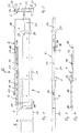
- the telescopic rail shown in Figures 1 to 3 with Locking device is provided for an insert, which is recorded in the area of a left side wall and from an inserted position into a blocking or lockable extended position is adjustable.
- the telescopic rail 2 is a three-part extension trained and shown very simplified. She points a cabinet-side rail 20 for attachment in one Cabinet, frame or housing and an intermediate rail 21 and a slide-in rail 22 as extendable rails on.
- lever rod 4 As an actuator on one additional holding element, which in this example is designed as a support bracket 6, pivotable attached.
- the support bracket 6 is on an inside 3 of the telescopic rail 2, in this embodiment on the intermediate rail 21, attached.
- the lever rod 4 is on one the telescopic rail 2 facing the outside of a vertical Leg 30 of the support bracket 6 attached.
- the attachment takes place in a warehouse 10, for example with the help a bearing pin, which in a bore of the lever rod 4 is added with play, so that the lever rod 4th "tumbling" is rotatably attached.
- Figure 1 shows the lever bar with dash-dotted lines 4 in a locking position in which the lever rod 4 is arranged obliquely and with a short lever arm 12 the support bracket 6 and with a long lever arm 13 the telescopic rail 2 is guided.
- the lever rods 4 In a definable Pulled out position, the lever rods 4 with a rear end portion 34 of the long lever arm 13 on one cabinet-side abutment 5 held and on sliding hindered.
- An upper abutment 5 is used as the cabinet Area of an end edge 19 of the rail 20 on the cabinet side intended.
- lever rod 4 The dimensions of the lever rod 4 in relation to those the support angle 6 and the rail links 20, 21, 22 the telescopic rail 2 are shown in Figures 1 to 3.
- Figure 2 shows that the lever rod 4 has a square Has cross section and in an upper region 26 and below an upper horizontal web 27 of the support angle 6 is attached.
- Figure 1 and Fig. 3 also illustrate the off-center storage, which dash-dotted in Fig. 1 shown oblique locking position of the lever rod 4 causes.
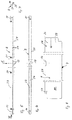
- FIG. 4 shows the lever rod 4.
- This lever rod 4 with Longitudinal axis 11 is axially parallel between in the longitudinal direction the support bracket 6 and the telescopic rail 2 are arranged (Fig. 1 to 3).
- the lever rod 4 is fastened via a bearing 10, whose axis of rotation is perpendicular to the longitudinal axis 11 runs.
- Fig. 8 is a blank 7 of the support angle 6, on which the lever rod 4 is pivotally attached, shown.
- the blank 7 shows that the support angle 6 produced particularly efficiently by a stamping and bending process can be.
- the upper horizontal web 27 is a right-angled Formed bend and has a recess 16 in which the lever rod 4 with a front end portion 35 the short lever arm 12 is sufficient. In the area of the recess 16 can be acted on the lever rod 4, this advantageously done by hand and thus controlled.
- a Insert for example a server insert, becomes double-armed held because the lever rods 4 in the bilateral telescopic rails depressed at the same time and the Insert is inserted.
- the upper horizontal web 27 of the support angle 6 is on its cabinet-side end with a recording 17.
- the support angle 6 has in a front area a locking element, for example a locking knob 28.
- An insert can be inserted between the receptacle 17 and the locking knob 28 in the area of a side wall with the help of a lifting bracket 8 are arranged and fixed, the complementary is formed to the support bracket 6 and thus a telescopic rail 2 completed.
- Figures 5 to 7 show a lifting angle 8, which with a upper vertical fastening web 23 on a side wall an insert can be attached. To this end mounting openings 31 are provided. A horizontal one Pad 24 is for resting on the upper horizontal Web 27 of the support angle 6 is provided and has approximately the same width. There is a lower vertical web formed by a second right-angled bend and forms a U-shaped guide for the short lever arm 12 the lever rod 4.
- the lifting angle 8 has a recess 18 in the horizontal support web 24 and in the lower vertical Provide web 25.
- the recess 18 is largely complementary formed for recess 16 in the support bracket 6 and allows the lever rod 4 to be pressed down into one Insert position (see Fig. 1).
Landscapes
- Drawers Of Furniture (AREA)
- Casings For Electric Apparatus (AREA)
- Pivots And Pivotal Connections (AREA)
- Vehicle Body Suspensions (AREA)
- Rear-View Mirror Devices That Are Mounted On The Exterior Of The Vehicle (AREA)
Applications Claiming Priority (2)
| Application Number | Priority Date | Filing Date | Title |
|---|---|---|---|
| DE29721865U | 1997-12-10 | ||
| DE29721865U DE29721865U1 (de) | 1997-12-10 | 1997-12-10 | Teleskopschiene |
Publications (2)
| Publication Number | Publication Date |
|---|---|
| EP0922417A2 true EP0922417A2 (fr) | 1999-06-16 |
| EP0922417A3 EP0922417A3 (fr) | 2002-01-02 |
Family
ID=8049788
Family Applications (1)
| Application Number | Title | Priority Date | Filing Date |
|---|---|---|---|
| EP98119609A Withdrawn EP0922417A3 (fr) | 1997-12-10 | 1998-10-16 | Glissière télescopique |
Country Status (2)
| Country | Link |
|---|---|
| EP (1) | EP0922417A3 (fr) |
| DE (1) | DE29721865U1 (fr) |
Cited By (1)
| Publication number | Priority date | Publication date | Assignee | Title |
|---|---|---|---|---|
| DE202004021512U1 (de) | 1990-04-03 | 2008-08-28 | Heinrich J. Kesseböhmer KG | Auszugsvorrichtung für Schrankauszüge, insbesondere in einem Hochschrank |
Citations (1)
| Publication number | Priority date | Publication date | Assignee | Title |
|---|---|---|---|---|
| DE19502526C1 (de) | 1995-01-27 | 1996-02-01 | Scheu Paul Friedhelm Dipl Kauf | Rollschubkastenregal |
Family Cites Families (3)
| Publication number | Priority date | Publication date | Assignee | Title |
|---|---|---|---|---|
| DE2508643A1 (de) * | 1975-02-28 | 1976-09-09 | Schwarzwaelder Kuechenmoebel W | Anschlagvorrichtung zum begrenzen des verschiebeweges eines an einem moebelkorpus hin und her bewegbar gefuehrten auszugs |
| CH600831A5 (fr) * | 1975-10-20 | 1978-06-30 | Hans Born | |
| DE4307911A1 (de) * | 1993-03-12 | 1994-09-15 | Scheu Paul Friedhelm Dipl Kauf | Rollschubkastenregal |
-
1997
- 1997-12-10 DE DE29721865U patent/DE29721865U1/de not_active Expired - Lifetime
-
1998
- 1998-10-16 EP EP98119609A patent/EP0922417A3/fr not_active Withdrawn
Patent Citations (1)
| Publication number | Priority date | Publication date | Assignee | Title |
|---|---|---|---|---|
| DE19502526C1 (de) | 1995-01-27 | 1996-02-01 | Scheu Paul Friedhelm Dipl Kauf | Rollschubkastenregal |
Cited By (1)
| Publication number | Priority date | Publication date | Assignee | Title |
|---|---|---|---|---|
| DE202004021512U1 (de) | 1990-04-03 | 2008-08-28 | Heinrich J. Kesseböhmer KG | Auszugsvorrichtung für Schrankauszüge, insbesondere in einem Hochschrank |
Also Published As
| Publication number | Publication date |
|---|---|
| EP0922417A3 (fr) | 2002-01-02 |
| DE29721865U1 (de) | 1998-01-29 |
Similar Documents
| Publication | Publication Date | Title |
|---|---|---|
| EP2012619B1 (fr) | Dispositif de guidage encastré pour éléments de meubles, en particulier de tiroirs dans le corps de meubles | |
| EP1419717B1 (fr) | Dispositif pour relier un rail de tiroir d'une garniture de glissières à un tiroir | |
| DE102013104829A1 (de) | Auszugsführung | |
| EP1479318A1 (fr) | Dispositif de coulissement pour tiroirs d'armoires, en particulier pour tiroirs verticaux | |
| DE202004015100U1 (de) | Befestigungsanordnung für die lösbare Befestigung von Ausziehführungen an Schubladen | |
| DE102019107385A1 (de) | Schiebe-Schwenkmechanik für eine Ablage eines Möbels oder Haushaltsgerätes und Möbel bzw. Haushaltsgerät | |
| EP2992156A1 (fr) | Système de guidage d'une porte coulissante, porte coulissante et meuble | |
| DE4224281A1 (de) | Auszugsvorrichtung für Schrankauszüge | |
| EP0841213B1 (fr) | Cendrier pour véhicule | |
| DE8802343U1 (de) | Auszug mit ankoppelbarem Schubkasten | |
| DE102010016594A1 (de) | Auszugsführung für Möbel oder Haushaltsgeräte | |
| EP1050246B1 (fr) | Placard | |
| EP0922417A2 (fr) | Glissière télescopique | |
| EP3624637A1 (fr) | Mécanisme de levage, meuble ou appareil ménager et tiroir | |
| EP0314964B1 (fr) | Armoire suspendue en tôle | |
| DE202004021512U1 (de) | Auszugsvorrichtung für Schrankauszüge, insbesondere in einem Hochschrank | |
| EP2301383B1 (fr) | Elément de liaison, cadre de meuble, bloc pour l'assemblage d'un support de meuble et système modulaire pour l'assemblage d'une pièce de meuble | |
| CH685167A5 (de) | Schrank mit beidseitig ausziehbarer Lade. | |
| DE10105847A1 (de) | Mitnahmevorrichtung für ausziehbaren Möbelboden | |
| EP1969963B1 (fr) | Dispositif de plateaux de table | |
| DE9402397U1 (de) | Möbelstück | |
| AT404221B (de) | Ausziehführungsgarnitur für schubladen | |
| EP4714299A2 (fr) | Agencement doté d'au moins un guide de sortie de tiroir | |
| DE20201094U1 (de) | Beschlag für einen Schiebetürschrank | |
| DE102021000976A1 (de) | Möblierungssystem |
Legal Events
| Date | Code | Title | Description |
|---|---|---|---|
| PUAI | Public reference made under article 153(3) epc to a published international application that has entered the european phase |
Free format text: ORIGINAL CODE: 0009012 |
|
| AK | Designated contracting states |
Kind code of ref document: A2 Designated state(s): AT BE CH CY DE DK ES FI FR GB GR IE IT LI LU MC NL PT SE |
|
| AX | Request for extension of the european patent |
Free format text: AL;LT;LV;MK;RO;SI |
|
| PUAL | Search report despatched |
Free format text: ORIGINAL CODE: 0009013 |
|
| AK | Designated contracting states |
Kind code of ref document: A3 Designated state(s): AT BE CH CY DE DK ES FI FR GB GR IE IT LI LU MC NL PT SE |
|
| AX | Request for extension of the european patent |
Free format text: AL;LT;LV;MK;RO;SI |
|
| RIC1 | Information provided on ipc code assigned before grant |
Free format text: 7A 47B 88/08 A, 7A 47B 88/04 B, 7A 47B 88/14 B, 7A 47B 88/16 B |
|
| AKX | Designation fees paid | ||
| REG | Reference to a national code |
Ref country code: DE Ref legal event code: 8566 |
|
| STAA | Information on the status of an ep patent application or granted ep patent |
Free format text: STATUS: THE APPLICATION IS DEEMED TO BE WITHDRAWN |
|
| 18D | Application deemed to be withdrawn |
Effective date: 20020703 |
|
| REG | Reference to a national code |
Ref country code: HK Ref legal event code: WD Ref document number: 1018735 Country of ref document: HK |