EP0922536A1 - Procédé et dispositif pour la pose de chevilles à expansion - Google Patents
Procédé et dispositif pour la pose de chevilles à expansion Download PDFInfo
- Publication number
- EP0922536A1 EP0922536A1 EP97121896A EP97121896A EP0922536A1 EP 0922536 A1 EP0922536 A1 EP 0922536A1 EP 97121896 A EP97121896 A EP 97121896A EP 97121896 A EP97121896 A EP 97121896A EP 0922536 A1 EP0922536 A1 EP 0922536A1
- Authority
- EP
- European Patent Office
- Prior art keywords
- blind rivet
- tensile force
- force
- bead
- cut
- Prior art date
- Legal status (The legal status is an assumption and is not a legal conclusion. Google has not performed a legal analysis and makes no representation as to the accuracy of the status listed.)
- Granted
Links
- 238000000034 method Methods 0.000 title claims abstract description 29
- 239000003638 chemical reducing agent Substances 0.000 claims abstract description 6
- 239000011324 bead Substances 0.000 claims description 13
- 230000008569 process Effects 0.000 claims description 12
- 230000006835 compression Effects 0.000 claims description 7
- 238000007906 compression Methods 0.000 claims description 7
- 239000000463 material Substances 0.000 claims description 5
- 230000003247 decreasing effect Effects 0.000 claims description 4
- 230000015572 biosynthetic process Effects 0.000 claims description 2
- 230000008878 coupling Effects 0.000 claims 1
- 238000010168 coupling process Methods 0.000 claims 1
- 238000005859 coupling reaction Methods 0.000 claims 1
- 230000009347 mechanical transmission Effects 0.000 claims 1
- 238000012545 processing Methods 0.000 description 4
- 230000005540 biological transmission Effects 0.000 description 3
- 238000012549 training Methods 0.000 description 3
- 238000013519 translation Methods 0.000 description 3
- 239000006096 absorbing agent Substances 0.000 description 2
- 238000010276 construction Methods 0.000 description 2
- 230000035939 shock Effects 0.000 description 2
- 230000009471 action Effects 0.000 description 1
- 230000033228 biological regulation Effects 0.000 description 1
- 230000008859 change Effects 0.000 description 1
- 230000000694 effects Effects 0.000 description 1
- 238000004146 energy storage Methods 0.000 description 1
- 230000002401 inhibitory effect Effects 0.000 description 1
- 230000004048 modification Effects 0.000 description 1
- 238000012986 modification Methods 0.000 description 1
- 230000000750 progressive effect Effects 0.000 description 1
- 230000009467 reduction Effects 0.000 description 1
- 239000000725 suspension Substances 0.000 description 1
Images


Classifications
-
- B—PERFORMING OPERATIONS; TRANSPORTING
- B21—MECHANICAL METAL-WORKING WITHOUT ESSENTIALLY REMOVING MATERIAL; PUNCHING METAL
- B21J—FORGING; HAMMERING; PRESSING METAL; RIVETING; FORGE FURNACES
- B21J15/00—Riveting
- B21J15/38—Accessories for use in connection with riveting, e.g. pliers for upsetting; Hand tools for riveting
- B21J15/386—Pliers for riveting
-
- B—PERFORMING OPERATIONS; TRANSPORTING
- B21—MECHANICAL METAL-WORKING WITHOUT ESSENTIALLY REMOVING MATERIAL; PUNCHING METAL
- B21J—FORGING; HAMMERING; PRESSING METAL; RIVETING; FORGE FURNACES
- B21J15/00—Riveting
- B21J15/10—Riveting machines
- B21J15/16—Drives for riveting machines; Transmission means therefor
- B21J15/20—Drives for riveting machines; Transmission means therefor operated by hydraulic or liquid pressure
- B21J15/205—Riveting tools having hand operated pumps for building up the hydraulic pressure
-
- B—PERFORMING OPERATIONS; TRANSPORTING
- B25—HAND TOOLS; PORTABLE POWER-DRIVEN TOOLS; MANIPULATORS
- B25B—TOOLS OR BENCH DEVICES NOT OTHERWISE PROVIDED FOR, FOR FASTENING, CONNECTING, DISENGAGING OR HOLDING
- B25B27/00—Hand tools, specially adapted for fitting together or separating parts or objects whether or not involving some deformation, not otherwise provided for
- B25B27/0007—Tools for fixing internally screw-threaded tubular fasteners
- B25B27/0014—Tools for fixing internally screw-threaded tubular fasteners motor-driven
-
- Y—GENERAL TAGGING OF NEW TECHNOLOGICAL DEVELOPMENTS; GENERAL TAGGING OF CROSS-SECTIONAL TECHNOLOGIES SPANNING OVER SEVERAL SECTIONS OF THE IPC; TECHNICAL SUBJECTS COVERED BY FORMER USPC CROSS-REFERENCE ART COLLECTIONS [XRACs] AND DIGESTS
- Y10—TECHNICAL SUBJECTS COVERED BY FORMER USPC
- Y10T—TECHNICAL SUBJECTS COVERED BY FORMER US CLASSIFICATION
- Y10T29/00—Metal working
- Y10T29/53—Means to assemble or disassemble
- Y10T29/53709—Overedge assembling means
- Y10T29/53717—Annular work
- Y10T29/53726—Annular work with second workpiece inside annular work one workpiece moved to shape the other
- Y10T29/5373—Annular work with second workpiece inside annular work one workpiece moved to shape the other comprising driver for snap-off-mandrel fastener; e.g., Pop [TM] riveter
- Y10T29/53739—Pneumatic- or fluid-actuated tool
- Y10T29/53743—Liquid
- Y10T29/53748—Liquid and gas
-
- Y—GENERAL TAGGING OF NEW TECHNOLOGICAL DEVELOPMENTS; GENERAL TAGGING OF CROSS-SECTIONAL TECHNOLOGIES SPANNING OVER SEVERAL SECTIONS OF THE IPC; TECHNICAL SUBJECTS COVERED BY FORMER USPC CROSS-REFERENCE ART COLLECTIONS [XRACs] AND DIGESTS
- Y10—TECHNICAL SUBJECTS COVERED BY FORMER USPC
- Y10T—TECHNICAL SUBJECTS COVERED BY FORMER US CLASSIFICATION
- Y10T29/00—Metal working
- Y10T29/53—Means to assemble or disassemble
- Y10T29/53709—Overedge assembling means
- Y10T29/53717—Annular work
- Y10T29/53726—Annular work with second workpiece inside annular work one workpiece moved to shape the other
- Y10T29/5373—Annular work with second workpiece inside annular work one workpiece moved to shape the other comprising driver for snap-off-mandrel fastener; e.g., Pop [TM] riveter
- Y10T29/53752—Annular work with second workpiece inside annular work one workpiece moved to shape the other comprising driver for snap-off-mandrel fastener; e.g., Pop [TM] riveter having rotary drive mechanism
-
- Y—GENERAL TAGGING OF NEW TECHNOLOGICAL DEVELOPMENTS; GENERAL TAGGING OF CROSS-SECTIONAL TECHNOLOGIES SPANNING OVER SEVERAL SECTIONS OF THE IPC; TECHNICAL SUBJECTS COVERED BY FORMER USPC CROSS-REFERENCE ART COLLECTIONS [XRACs] AND DIGESTS
- Y10—TECHNICAL SUBJECTS COVERED BY FORMER USPC
- Y10T—TECHNICAL SUBJECTS COVERED BY FORMER US CLASSIFICATION
- Y10T29/00—Metal working
- Y10T29/53—Means to assemble or disassemble
- Y10T29/53709—Overedge assembling means
- Y10T29/53717—Annular work
- Y10T29/53726—Annular work with second workpiece inside annular work one workpiece moved to shape the other
- Y10T29/5373—Annular work with second workpiece inside annular work one workpiece moved to shape the other comprising driver for snap-off-mandrel fastener; e.g., Pop [TM] riveter
- Y10T29/53757—Annular work with second workpiece inside annular work one workpiece moved to shape the other comprising driver for snap-off-mandrel fastener; e.g., Pop [TM] riveter having allochiral actuating handles
Definitions
- the invention relates to a method for setting Blind rivet nuts, in which the mandrel up to the stop is screwed into the nut thread in the nut thread and then axially displaced so that the thin-walled material of the cut part dodges outwards and one Bead forms.
- the traction applied is such a procedure not constant during the entire riveting process, rather, for example, two are towards each other moving hand levers towards the end of the movement force applied is greatest.
- the greatest force is required at the time when the material of the cut out part begins to move outwards while with progressive movement an ever smaller Force is required until the end of the riveting process must be broken off when the bead hits the wall the borehole to damage the thread avoid.
- the wall thickness in the cut part of the Blind rivet nut is preferably chosen so that the Clamping force of the bead being formed is as large as possible later act as an anti-twist device.
- the invention is therefore based on the object To make available a process in which the setting of Blind rivet nuts easier, safer and more economical is made possible.
- the mentioned type suggested that one from the beginning of the axial Movement of the blind rivet nut applied decreasing tensile force becomes.
- the invention also makes a device Implementation of the procedure available.
- a device for setting blind rivet nuts to carry out the A method according to claim 1 or 2, which has a tensile force Formation of a bead through the thin-walled, applies the cut-out part to the blind rivet nut, is characterized in that a decrease in traction mechanical translation is provided.
- a decrease in traction Pressure reducer is provided.
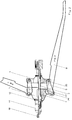
- Fig. 1 shows a mechanical device consisting of a transverse bearing 1 in which a guide tube 2 is fixed is screwed, which serves to mount the housing 3, so that this is axially displaceable against the transverse bearing 1.
- a mandrel 4 which by the Guide tube 2 protrudes from the housing 3 and there is connected to the mandrel 10.
- the mouthpiece 11 is screwed in and over a Knurled nut 12 countered.
- the cross bearing 1 is with the Housing 3 connected by the lever arms 8 in the transverse bearing 1 be stored with a cross pin 7 and the tabs 6 in Housing 3 with a cross pin 5 and in the lever arm 8 with a cross pin 9 are stored.
- Fig. 2 shows a further solution, the is that the cross bearing 1 with the housing 3rd is connected by the lever arms 8 in the housing 3 with a Cross pin 2, 7, 27 are stored and the tabs 6 in Cross bearing 1 with a cross pin 2, 5, 25 and in lever arm 8 be stored with a cross pin 2, 9, 29.
- the housing 3 with the mouthpiece 11 against the Threaded mandrel 10 with a likewise decreasing Power transmission When pressed lever arm from position 1 to position 2 the housing 3 with the mouthpiece 11 against the Threaded mandrel 10 with a likewise decreasing Power transmission.
- Fig. 3 shows a modification in which a mechanical device consists of a transverse bearing 31 in which a guide tube 32 is screwed, which for Storage of the housing 33 is used so that this against the Cross bearing 31 is axially displaceable.
- a mechanical device consists of a transverse bearing 31 in which a guide tube 32 is screwed, which for Storage of the housing 33 is used so that this against the Cross bearing 31 is axially displaceable.
- cross bearing 31 and housing 33 move away from one another, what with one in between and both connected spring 34 to a constant increase in Resistance leads.
- Fig. 4 Another solution, particularly suitable for hydro-pneumatically driven tools, is in Fig. 4 shown and is the stroke against a increasing power to drive.
- Any type of spring is suitable or suspension or a construction based on the system of the shock absorber.
- the pulling force of the device can change during the stroke can be reduced by doubling the pneumatic cylinder acting cylinder is designed and initially on the return stroke after riveting against a compression spring 57 runs and part of the necessary for the next step Force thus saves. This not only does the desired thing degressive traction, but also allows an essential one Improve the performance of the cylinder, which is either has more power or can be designed accordingly smaller can.
- the tensile force can also be applied to mechanical tools can be reduced during the stroke by the spring 4 is designed as a compression spring and when opening the tool part of the necessary for the next step Strength stores. This not only does the desired thing degressive traction, but also allows an essential one Improve the performance of the tool, which is more Force generated or designed accordingly smaller can.
- the spring can be designed so that when Supporting the beginning of the riveting process and in the final phase has an inhibitory effect. This is accomplished by one and the same Spring used both as a compression spring and as a tension spring becomes. When the tool returns, it passes over hers relaxed state into a state storing the strength and thus acts as a compression spring. Supported during the riveting process the spring pulls the tension of the Degressive tool, as already described, then as Tension spring to reduce this force even more.
- Oil brakes, shock absorbers, frictional resistances of all kinds all are nevertheless suitable for achieving the same technical effect.
Landscapes
- Engineering & Computer Science (AREA)
- Mechanical Engineering (AREA)
- Insertion Pins And Rivets (AREA)
- Transmission Devices (AREA)
- Actuator (AREA)
Priority Applications (6)
| Application Number | Priority Date | Filing Date | Title |
|---|---|---|---|
| DE59709449T DE59709449D1 (de) | 1997-12-12 | 1997-12-12 | Gerät zum Setzen von Blindnietmuttern |
| EP97121896A EP0922536B1 (fr) | 1997-12-12 | 1997-12-12 | Dispositif pour la pose de chevilles à expansion |
| EP19970122340 EP0936029B1 (fr) | 1997-12-12 | 1997-12-18 | Dispositif pour la pose de rivets/écrous aveugles |
| DE59703154T DE59703154D1 (de) | 1997-12-12 | 1997-12-18 | Gerät zum Setzen von Blindnietmuttern |
| US09/211,520 US6029332A (en) | 1997-12-12 | 1998-12-14 | Rivet setting tool |
| US09/456,969 US6223409B1 (en) | 1997-12-12 | 1999-12-07 | Rivet setting tool |
Applications Claiming Priority (2)
| Application Number | Priority Date | Filing Date | Title |
|---|---|---|---|
| EP97121896A EP0922536B1 (fr) | 1997-12-12 | 1997-12-12 | Dispositif pour la pose de chevilles à expansion |
| US09/211,520 US6029332A (en) | 1997-12-12 | 1998-12-14 | Rivet setting tool |
Publications (2)
| Publication Number | Publication Date |
|---|---|
| EP0922536A1 true EP0922536A1 (fr) | 1999-06-16 |
| EP0922536B1 EP0922536B1 (fr) | 2003-03-05 |
Family
ID=26145977
Family Applications (1)
| Application Number | Title | Priority Date | Filing Date |
|---|---|---|---|
| EP97121896A Expired - Lifetime EP0922536B1 (fr) | 1997-12-12 | 1997-12-12 | Dispositif pour la pose de chevilles à expansion |
Country Status (2)
| Country | Link |
|---|---|
| US (2) | US6029332A (fr) |
| EP (1) | EP0922536B1 (fr) |
Cited By (2)
| Publication number | Priority date | Publication date | Assignee | Title |
|---|---|---|---|---|
| CN101992255B (zh) * | 2009-08-14 | 2012-07-04 | 上海安字实业有限公司 | 顶推式铆接传动装置 |
| DE102017112231B4 (de) | 2017-06-02 | 2024-02-29 | Heiko Schmidt | Verfahren zum Verankern von Verbindungselementen in ein bleibend verformbares metallisches Flachmaterial oder daraus hergestellte Bauteile oder Werkstücke, Verbindungselement sowie Setzwerkzeug |
Families Citing this family (11)
| Publication number | Priority date | Publication date | Assignee | Title |
|---|---|---|---|---|
| EP0922536B1 (fr) * | 1997-12-12 | 2003-03-05 | Herbert Schruff | Dispositif pour la pose de chevilles à expansion |
| US6487767B1 (en) | 2000-04-10 | 2002-12-03 | Fatigue Technology, Inc. | Method and apparatus for connecting a fastener element to a wall |
| DE20112171U1 (de) * | 2001-07-23 | 2001-10-11 | Böllhoff GmbH, 33649 Bielefeld | Schraubblindniet-Verbindungsanordnung |
| CZ12144U1 (cs) * | 2002-02-18 | 2002-03-28 | Ms Nářadí, S.R.O. | Upínací spoj výměnného trnu a taľného čepu nýtovacího nástroje a pouľití tohoto upínacího spoje pro ruční nýtovací nástroj |
| US20050211452A1 (en) * | 2004-03-24 | 2005-09-29 | A Major Corporation | Spring powered hand tool |
| US7237413B2 (en) * | 2005-04-26 | 2007-07-03 | Acument Intellectual Properties Llc | Setting tool |
| GB201002954D0 (en) * | 2010-02-22 | 2010-04-07 | Hastings John K | A tool for installing rivet nuts |
| US8707530B2 (en) * | 2012-03-20 | 2014-04-29 | Yu-Ching Lin | Rivet gun with a changeable cylinder |
| CN104117622B (zh) * | 2013-04-26 | 2016-06-08 | 苏州富士特金属薄板制品有限公司 | 一种拉铆螺母专用铆接头 |
| TWI551371B (zh) * | 2013-05-22 | 2016-10-01 | Karat Ind Corp | Replace the pull rod drive device pull cap (pull bolt) tool |
| EP3981990B1 (fr) * | 2020-10-07 | 2025-01-15 | SFS Group Germany GmbH | Procédé de raccordement d'une pluralité d'objets individuels au moyen d'une structure porteuse et ensemble de montage |
Citations (10)
| Publication number | Priority date | Publication date | Assignee | Title |
|---|---|---|---|---|
| FR2343564A1 (fr) * | 1976-03-11 | 1977-10-07 | Brendle Robert | Outil de mise en place de cheville taraudee |
| FR2354853A1 (fr) * | 1976-06-17 | 1978-01-13 | Futters London Ltd | Outil pour la mise en place de chevilles expansives |
| DE2739166A1 (de) * | 1977-08-31 | 1979-03-08 | Bachler S A Soc Nouv Ets | Zange zum einsetzen von spreizbaren schraubduebeln |
| GB2130514A (en) * | 1982-11-18 | 1984-06-06 | Spurway Cooke Ind Pty Ltd | Blind-rivet setting tool |
| EP0159255A1 (fr) * | 1984-03-29 | 1985-10-23 | Etablissements Pierre Grehal Et Compagnie | Pince pour la pose de chevilles à expansion comportant deux bras articulés |
| GB2172233A (en) * | 1985-03-16 | 1986-09-17 | Honsel Nieten & Metallwarenfab | Hand riveter with force limitation |
| DE3701883A1 (de) * | 1987-01-23 | 1988-08-04 | Honsel Nieten & Metallwarenfab | Blindnietsetzwerkzeug |
| EP0445084A2 (fr) * | 1990-03-02 | 1991-09-04 | FAR S.r.l. | Outil pour la mise en place d'insert taraudé creux |
| DE9408203U1 (de) * | 1994-05-18 | 1994-07-14 | Liu, Yang Tein, Yuan-Li, Miao-Li | Nietpistole |
| FR2724856A1 (fr) * | 1994-09-26 | 1996-03-29 | Otalu Sa Soc | Dispositif de controle pour le sertissage des ecrous noyes |
Family Cites Families (12)
| Publication number | Priority date | Publication date | Assignee | Title |
|---|---|---|---|---|
| US2399442A (en) * | 1942-06-19 | 1946-04-30 | Richard W Luce | Tool |
| US2384347A (en) * | 1943-11-11 | 1945-09-04 | Steinway & Sons | Cage nut tool |
| DE2537792C3 (de) * | 1975-08-25 | 1986-11-13 | Alfred Honsel Nieten - und Metallwarenfabrik GmbH & Co, 5758 Fröndenberg | Blindnietgerät |
| DE3125838A1 (de) * | 1981-07-01 | 1983-01-27 | Manfred 6200 Wiesbaden Schwab | Blindnietgeraet mit nietstiftfoerderung |
| DE3306827C2 (de) * | 1983-02-26 | 1986-05-07 | Gesipa Blindniettechnik Gmbh, 6000 Frankfurt | Pneumatisch-hydraulisches Setzgerät für Blindnietmuttern |
| GB2152421B (en) * | 1984-01-13 | 1987-10-07 | Honsel Nieten & Metallwarenfab | Blind riveting apparatus for rivets of different sizes |
| EP0441223A3 (en) * | 1990-02-06 | 1992-03-04 | Maschinenbau Subotsch & Schwab Gmbh | Hydraulically or hand operated riveting tool |
| US5050420A (en) * | 1990-08-29 | 1991-09-24 | Liu Yang Ting | Multi-functional riveter |
| DE9110718U1 (de) * | 1991-08-29 | 1992-06-04 | Alfred Honsel Nieten- und Metallwarenfabrik GmbH & Co, 5758 Fröndenberg | Blindniet-Handzange |
| US5575051A (en) * | 1993-06-10 | 1996-11-19 | Marson/Creative Fastener Group | High impact power tool having shock absorbing means |
| TW316504U (en) * | 1996-12-26 | 1997-09-21 | Teiko & Sons Corp | Nut riveting tool having fixed hole |
| EP0922536B1 (fr) * | 1997-12-12 | 2003-03-05 | Herbert Schruff | Dispositif pour la pose de chevilles à expansion |
-
1997
- 1997-12-12 EP EP97121896A patent/EP0922536B1/fr not_active Expired - Lifetime
-
1998
- 1998-12-14 US US09/211,520 patent/US6029332A/en not_active Expired - Fee Related
-
1999
- 1999-12-07 US US09/456,969 patent/US6223409B1/en not_active Expired - Fee Related
Patent Citations (10)
| Publication number | Priority date | Publication date | Assignee | Title |
|---|---|---|---|---|
| FR2343564A1 (fr) * | 1976-03-11 | 1977-10-07 | Brendle Robert | Outil de mise en place de cheville taraudee |
| FR2354853A1 (fr) * | 1976-06-17 | 1978-01-13 | Futters London Ltd | Outil pour la mise en place de chevilles expansives |
| DE2739166A1 (de) * | 1977-08-31 | 1979-03-08 | Bachler S A Soc Nouv Ets | Zange zum einsetzen von spreizbaren schraubduebeln |
| GB2130514A (en) * | 1982-11-18 | 1984-06-06 | Spurway Cooke Ind Pty Ltd | Blind-rivet setting tool |
| EP0159255A1 (fr) * | 1984-03-29 | 1985-10-23 | Etablissements Pierre Grehal Et Compagnie | Pince pour la pose de chevilles à expansion comportant deux bras articulés |
| GB2172233A (en) * | 1985-03-16 | 1986-09-17 | Honsel Nieten & Metallwarenfab | Hand riveter with force limitation |
| DE3701883A1 (de) * | 1987-01-23 | 1988-08-04 | Honsel Nieten & Metallwarenfab | Blindnietsetzwerkzeug |
| EP0445084A2 (fr) * | 1990-03-02 | 1991-09-04 | FAR S.r.l. | Outil pour la mise en place d'insert taraudé creux |
| DE9408203U1 (de) * | 1994-05-18 | 1994-07-14 | Liu, Yang Tein, Yuan-Li, Miao-Li | Nietpistole |
| FR2724856A1 (fr) * | 1994-09-26 | 1996-03-29 | Otalu Sa Soc | Dispositif de controle pour le sertissage des ecrous noyes |
Cited By (2)
| Publication number | Priority date | Publication date | Assignee | Title |
|---|---|---|---|---|
| CN101992255B (zh) * | 2009-08-14 | 2012-07-04 | 上海安字实业有限公司 | 顶推式铆接传动装置 |
| DE102017112231B4 (de) | 2017-06-02 | 2024-02-29 | Heiko Schmidt | Verfahren zum Verankern von Verbindungselementen in ein bleibend verformbares metallisches Flachmaterial oder daraus hergestellte Bauteile oder Werkstücke, Verbindungselement sowie Setzwerkzeug |
Also Published As
| Publication number | Publication date |
|---|---|
| US6029332A (en) | 2000-02-29 |
| US6223409B1 (en) | 2001-05-01 |
| EP0922536B1 (fr) | 2003-03-05 |
Similar Documents
| Publication | Publication Date | Title |
|---|---|---|
| DE69727316T2 (de) | Linear bewegender piezoelektrischer motor für anwendung in motorfahrzeugen | |
| EP0922536B1 (fr) | Dispositif pour la pose de chevilles à expansion | |
| DE1803417B2 (de) | Zug- und Stoßvorrichtung für Eisenbahnwagen | |
| EP0535717A2 (fr) | Servodirection hydraulique pour véhicules automobiles | |
| EP1272785B1 (fr) | Procede et dispositif pour fixer de maniere etanche une piece tubulaire en materiau elastomere sur une partie de raccordement | |
| EP2399712B1 (fr) | Appareil de fixation doté d'un réglage de levée de siège variable | |
| DE2653714C2 (de) | Schnittschlagdämpfungseinrichtung für Stanzpressen | |
| DE102008013374A1 (de) | Hydropneumatische Vorrichtung zur Druckübersetzung | |
| DE102009042806A1 (de) | Pedalanordnung zur Kupplungsbetätigung | |
| DE602004007472T2 (de) | Motorisierter Aktuator für Fahrradgangschaltung, mit kontrolliertem Reibungsmechanismus | |
| DE2611533C2 (de) | Antriebsorgan | |
| EP2404078B1 (fr) | Système d'amortissement pour amortissement de butée | |
| DE2347419A1 (de) | Kraftuebertragungs-vorrichtung | |
| DE19861137C2 (de) | Stelleinrichtung zur automatisierten Betätigung eines Schaltgetriebes | |
| EP0881134A2 (fr) | Accumulateur d'energie | |
| EP1169152B1 (fr) | Dispositif pour l'usinage de tiges a bague de serrage | |
| DE2514407C2 (de) | Mechanische Betätigungseinrichtung für ein Steuerventil eines Getriebes | |
| DE102017221955B4 (de) | Radaufhängung für ein Fahrzeug mit einer Niveauverstellung | |
| EP0936029B1 (fr) | Dispositif pour la pose de rivets/écrous aveugles | |
| DE2454061A1 (de) | Verfahren und vorrichtung zum regeln der beschleunigung von motoren | |
| CH693323A5 (de) | Einspannvorrichtung für einSägeblatt. | |
| DE69721954T2 (de) | Federgespannter, mechanischer Expander mit festgelegter Vorspannung und konstanter Referenz- Position | |
| DE7425102U (de) | Dämpfungsvorrichtung für Stoßstangen | |
| DE2609118A1 (de) | Arbeitszylinder | |
| EP0628466A1 (fr) | Procédé et dispositif de réglage de la position hydraulique neutre d'une valve dans circuit d'assistance |
Legal Events
| Date | Code | Title | Description |
|---|---|---|---|
| PUAI | Public reference made under article 153(3) epc to a published international application that has entered the european phase |
Free format text: ORIGINAL CODE: 0009012 |
|
| AK | Designated contracting states |
Kind code of ref document: A1 Designated state(s): DE ES FR GB IT NL SE |
|
| AX | Request for extension of the european patent |
Free format text: AL;LT;LV;MK;RO;SI |
|
| 17P | Request for examination filed |
Effective date: 19991209 |
|
| AKX | Designation fees paid |
Free format text: AT BE CH DE DK ES FI LI |
|
| RBV | Designated contracting states (corrected) |
Designated state(s): DE ES FR GB IT NL SE |
|
| 17Q | First examination report despatched |
Effective date: 20010305 |
|
| RTI1 | Title (correction) |
Free format text: DEVICE FOR PLACING RIVET NUTS |
|
| GRAH | Despatch of communication of intention to grant a patent |
Free format text: ORIGINAL CODE: EPIDOS IGRA |
|
| GRAH | Despatch of communication of intention to grant a patent |
Free format text: ORIGINAL CODE: EPIDOS IGRA |
|
| GRAA | (expected) grant |
Free format text: ORIGINAL CODE: 0009210 |
|
| AK | Designated contracting states |
Designated state(s): DE ES FR GB IT NL SE |
|
| PG25 | Lapsed in a contracting state [announced via postgrant information from national office to epo] |
Ref country code: NL Free format text: LAPSE BECAUSE OF FAILURE TO SUBMIT A TRANSLATION OF THE DESCRIPTION OR TO PAY THE FEE WITHIN THE PRESCRIBED TIME-LIMIT Effective date: 20030305 Ref country code: IT Free format text: LAPSE BECAUSE OF FAILURE TO SUBMIT A TRANSLATION OF THE DESCRIPTION OR TO PAY THE FEE WITHIN THE PRE;WARNING: LAPSES OF ITALIAN PATENTS WITH EFFECTIVE DATE BEFORE 2007 MAY HAVE OCCURRED AT ANY TIME BEFORE 2007. THE CORRECT EFFECTIVE DATE MAY BE DIFFERENT FROM THE ONE RECORDED.SCRIBED TIME-LIMIT Effective date: 20030305 |
|
| REG | Reference to a national code |
Ref country code: GB Ref legal event code: FG4D Free format text: NOT ENGLISH |
|
| REF | Corresponds to: |
Ref document number: 59709449 Country of ref document: DE Date of ref document: 20030410 Kind code of ref document: P |
|
| PG25 | Lapsed in a contracting state [announced via postgrant information from national office to epo] |
Ref country code: SE Free format text: LAPSE BECAUSE OF FAILURE TO SUBMIT A TRANSLATION OF THE DESCRIPTION OR TO PAY THE FEE WITHIN THE PRESCRIBED TIME-LIMIT Effective date: 20030605 |
|
| GBT | Gb: translation of ep patent filed (gb section 77(6)(a)/1977) | ||
| NLV1 | Nl: lapsed or annulled due to failure to fulfill the requirements of art. 29p and 29m of the patents act | ||
| PG25 | Lapsed in a contracting state [announced via postgrant information from national office to epo] |
Ref country code: ES Free format text: LAPSE BECAUSE OF FAILURE TO SUBMIT A TRANSLATION OF THE DESCRIPTION OR TO PAY THE FEE WITHIN THE PRESCRIBED TIME-LIMIT Effective date: 20030930 |
|
| ET | Fr: translation filed | ||
| PLBE | No opposition filed within time limit |
Free format text: ORIGINAL CODE: 0009261 |
|
| STAA | Information on the status of an ep patent application or granted ep patent |
Free format text: STATUS: NO OPPOSITION FILED WITHIN TIME LIMIT |
|
| 26N | No opposition filed |
Effective date: 20031208 |
|
| PGFP | Annual fee paid to national office [announced via postgrant information from national office to epo] |
Ref country code: GB Payment date: 20061221 Year of fee payment: 10 Ref country code: DE Payment date: 20061221 Year of fee payment: 10 |
|
| PGFP | Annual fee paid to national office [announced via postgrant information from national office to epo] |
Ref country code: FR Payment date: 20061212 Year of fee payment: 10 |
|
| GBPC | Gb: european patent ceased through non-payment of renewal fee |
Effective date: 20071212 |
|
| PG25 | Lapsed in a contracting state [announced via postgrant information from national office to epo] |
Ref country code: DE Free format text: LAPSE BECAUSE OF NON-PAYMENT OF DUE FEES Effective date: 20080701 |
|
| REG | Reference to a national code |
Ref country code: FR Ref legal event code: ST Effective date: 20081020 |
|
| PG25 | Lapsed in a contracting state [announced via postgrant information from national office to epo] |
Ref country code: GB Free format text: LAPSE BECAUSE OF NON-PAYMENT OF DUE FEES Effective date: 20071212 |
|
| PG25 | Lapsed in a contracting state [announced via postgrant information from national office to epo] |
Ref country code: FR Free format text: LAPSE BECAUSE OF NON-PAYMENT OF DUE FEES Effective date: 20071231 |