EP0922603A1 - Vorratsbehälter für den Kraftstofftank eines Kraftfahrzeuges - Google Patents
Vorratsbehälter für den Kraftstofftank eines Kraftfahrzeuges Download PDFInfo
- Publication number
- EP0922603A1 EP0922603A1 EP98403101A EP98403101A EP0922603A1 EP 0922603 A1 EP0922603 A1 EP 0922603A1 EP 98403101 A EP98403101 A EP 98403101A EP 98403101 A EP98403101 A EP 98403101A EP 0922603 A1 EP0922603 A1 EP 0922603A1
- Authority
- EP
- European Patent Office
- Prior art keywords
- bowl
- bowls
- tank
- fuel
- conduit
- Prior art date
- Legal status (The legal status is an assumption and is not a legal conclusion. Google has not performed a legal analysis and makes no representation as to the accuracy of the status listed.)
- Granted
Links
Images


Classifications
-
- B—PERFORMING OPERATIONS; TRANSPORTING
- B60—VEHICLES IN GENERAL
- B60K—ARRANGEMENT OR MOUNTING OF PROPULSION UNITS OR OF TRANSMISSIONS IN VEHICLES; ARRANGEMENT OR MOUNTING OF PLURAL DIVERSE PRIME-MOVERS IN VEHICLES; AUXILIARY DRIVES FOR VEHICLES; INSTRUMENTATION OR DASHBOARDS FOR VEHICLES; ARRANGEMENTS IN CONNECTION WITH COOLING, AIR INTAKE, GAS EXHAUST OR FUEL SUPPLY OF PROPULSION UNITS IN VEHICLES
- B60K15/00—Arrangement in connection with fuel supply of combustion engines or other fuel consuming energy converters, e.g. fuel cells; Mounting or construction of fuel tanks
- B60K15/03—Fuel tanks
- B60K15/06—Fuel tanks characterised by fuel reserve systems
-
- B—PERFORMING OPERATIONS; TRANSPORTING
- B60—VEHICLES IN GENERAL
- B60K—ARRANGEMENT OR MOUNTING OF PROPULSION UNITS OR OF TRANSMISSIONS IN VEHICLES; ARRANGEMENT OR MOUNTING OF PLURAL DIVERSE PRIME-MOVERS IN VEHICLES; AUXILIARY DRIVES FOR VEHICLES; INSTRUMENTATION OR DASHBOARDS FOR VEHICLES; ARRANGEMENTS IN CONNECTION WITH COOLING, AIR INTAKE, GAS EXHAUST OR FUEL SUPPLY OF PROPULSION UNITS IN VEHICLES
- B60K15/00—Arrangement in connection with fuel supply of combustion engines or other fuel consuming energy converters, e.g. fuel cells; Mounting or construction of fuel tanks
- B60K15/03—Fuel tanks
- B60K15/077—Fuel tanks with means modifying or controlling distribution or motion of fuel, e.g. to prevent noise, surge, splash or fuel starvation
-
- B—PERFORMING OPERATIONS; TRANSPORTING
- B60—VEHICLES IN GENERAL
- B60K—ARRANGEMENT OR MOUNTING OF PROPULSION UNITS OR OF TRANSMISSIONS IN VEHICLES; ARRANGEMENT OR MOUNTING OF PLURAL DIVERSE PRIME-MOVERS IN VEHICLES; AUXILIARY DRIVES FOR VEHICLES; INSTRUMENTATION OR DASHBOARDS FOR VEHICLES; ARRANGEMENTS IN CONNECTION WITH COOLING, AIR INTAKE, GAS EXHAUST OR FUEL SUPPLY OF PROPULSION UNITS IN VEHICLES
- B60K15/00—Arrangement in connection with fuel supply of combustion engines or other fuel consuming energy converters, e.g. fuel cells; Mounting or construction of fuel tanks
- B60K15/03—Fuel tanks
- B60K2015/03236—Fuel tanks characterised by special filters, the mounting thereof
-
- B—PERFORMING OPERATIONS; TRANSPORTING
- B60—VEHICLES IN GENERAL
- B60K—ARRANGEMENT OR MOUNTING OF PROPULSION UNITS OR OF TRANSMISSIONS IN VEHICLES; ARRANGEMENT OR MOUNTING OF PLURAL DIVERSE PRIME-MOVERS IN VEHICLES; AUXILIARY DRIVES FOR VEHICLES; INSTRUMENTATION OR DASHBOARDS FOR VEHICLES; ARRANGEMENTS IN CONNECTION WITH COOLING, AIR INTAKE, GAS EXHAUST OR FUEL SUPPLY OF PROPULSION UNITS IN VEHICLES
- B60K15/00—Arrangement in connection with fuel supply of combustion engines or other fuel consuming energy converters, e.g. fuel cells; Mounting or construction of fuel tanks
- B60K15/03—Fuel tanks
- B60K2015/03328—Arrangements or special measures related to fuel tanks or fuel handling
- B60K2015/03453—Arrangements or special measures related to fuel tanks or fuel handling for fixing or mounting parts of the fuel tank together
- B60K2015/03467—Arrangements or special measures related to fuel tanks or fuel handling for fixing or mounting parts of the fuel tank together by clip or snap fit fittings
Definitions
- the invention relates to reserve devices for vehicle fuel tank.
- a two-pocket vehicle fuel tank automobile comprising a tank and two reserve bowls introduced into the tank through an opening respective upper pocket to extend to bottom of the associated pocket.
- These bowls allow reserve a reserve of fuel for emergency use when the tank is almost empty.
- this tank has the disadvantage that it requires introduce into the tank and position each of the bowls, which is relatively long.
- the capacity of the reserve bowl is limited by dimensions of the opening of the associated pocket allowing its introduction, as well as by the general pocket configuration. For example, it is not possible to put a bowl of cylindrical reserve with a capacity greater than volume defined by the section of the opening multiplied by the height between this opening and the bottom of the poached.
- An object of the invention is to provide a device easy and quick to install in a tank and having a large capacity compared to the dimensions opening and configuration of the tank which it is intended for.
- a reserve device for a vehicle fuel tank comprising at least two reserve bowls, and connecting means adapted to connect the two bowls to each other by a non-binding rigid.
- both bowls can be placed in one position relative to each other different from the final relative position expected for the two bowls in tank.
- we keep good control of the two bowls and the introduction maneuver is simple to execute.
- the connecting means are adapted to connect the two bowls by a joint.
- the connecting means comprise at least one flexible part adapted to connect the two bowls.
- the joint is thus formed particularly simple.
- the connecting means are of a single piece with one of the bowls and are suitable to be attached to the other bowl.
- the connecting means are adapted to be fixed to the other bowl by snap-fastening.
- the connecting means are adapted to connect the bases of each bowl to each other.
- one of the bowls has a more large section along a transverse plane parallel to a base of the bowl, of the same general shape as a plus large section of the other bowl following a plan transverse perpendicular to a base of the other bowl and parallel to an axis of the joint.
- the reserve device has a particularly large capacity compared to dimensions of the opening of a tank just greater than those in this section.
- one of the bowls has a general shape profiled in a direction perpendicular to a base of the bowl, the other bowl having a general shape profiled in a direction, perpendicular to a base of the other bowl and parallel to an axis of the joint.
- the device comprises means stiffening to rigidly connect the two bowls to one another.
- the stability of the device is improved. reserve once it is introduced into a tank.
- the stiffening means are adapted to cooperate with the connecting means for rigidly connect the two bowls.
- the stiffening means include latching means.
- the device comprises a conduit suitable for ensuring fuel communication directly from one to the other of the bowls.
- the device comprises a valve non-return valve arranged to allow a supply of fuel from a first of the bowls by means of the conduit to from a second of the bowls, prohibiting a fuel supply to the second bowl using the leads from the first bowl.
- the conduit connects a most bass from one of the bowls to a lowest area of the other bowl.
- the device is designed to allow fuel to be transferred from one of the bowls directly to the other bowl, over edges of the two bowls.
- one of the bowls is suitable for feeding the other by overflow.
- At least one of the two bowls has a cover partially sealing off an area top of the bowl.
- the device comprises at least one filter arranged to allow a supply of fuel from one of the woods from the tank to through the filter.
- each filter extends under one respective bowls.
- the filter is adapted to extend below the other bowl.
- a reservoir is also provided.
- vehicle fuel comprising a tank and a device according to the invention.
- the tank has an opening allowing the bowls of the device, the opening having just dimensions sufficient for the introduction of one of the bowls.
- this bowl is optimized by relative to the dimensions of the opening.
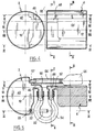
- the reserve device comprises a first bowl 2, here bowl main, and a second bowl 4, here auxiliary bowl.
- Each of the two bowls is made of one plastic holding.
- Each bowl 2, 4 has a generally profiled shape cylindrical with a straight circular cross section.
- the main bowl 2 and auxiliary bowl 4 each have a base 6, 8 with feet allowing them to stand on a flat surface of a fuel tank of motor vehicle.
- Base 6 of main bowl 2 extends at an axial end of the cylinder in a plane general perpendicular to a longitudinal axis 10 of the cylinder.
- the base 8 of the auxiliary bowl 4 extends along of a generator of the cylinder in a general plane parallel to a longitudinal axis 12 of the cylinder.
- the main bowl 2 is adapted to rest with the cylinder "standing" on the base 6, and the auxiliary bowl 4 is suitable to rest with the cylinder "lying" on the base 8.
- Main bowl 2 has an upper free edge 14 defining an open upper axial end of the main bowl 2 opposite its base 6.
- the two cylinders have substantially the same diameters.
- the bowl auxiliary 4 comprises a cover 16, of planar shape and extending parallel to base 8, sparing only a small hole 18 in the upper part of the auxiliary bowl 4.
- the auxiliary bowl 4 has two legs 20, 22 each of general shape elongated plane extending from one end axial of the bowl, parallel to the axis 12 in the direction opposite the bowl.
- Leg 20 has a rigorously shaped plane.
- the tab 22 has an angled "L" shape and extends parallel to axis 12, then perpendicular to this one, in the direction of this axis.
- Each of the legs 20, 22 has a lug at its free end. Both legs extend on either side of a plane median longitudinal of the auxiliary bowl 4 perpendicular at its base 8.
- the main bowl 2 has two housings 24, 26 adapted to receive the respective legs 20, 22 for click into place to prevent removal of legs, once these are inserted in the housings. These two housings 24, 26 extend in the vicinity of the base 6 of the main bowl 2. Each housing is defined between a tongue of the main bowl 2 and the wall of the bowl opposite.
- the legs 20, 22 and the housings 24, 26 are arranged so that when the legs and housings are snapped in, the main bowl 2 and the bowl auxiliary 4 can rest by means of their bases 6, 8 on a common plane support, with axis 10 of the bowl main 2 perpendicular to the axis 12 of the auxiliary bowl 4, the two axes being intersecting, and this without the legs 20, 22 are not stressed.
- An extremity axial of the auxiliary bowl 4 then extends opposite and at in the vicinity of a wall of the main bowl 2, in parallel to a generator of this wall.
- the legs 20, 22 are configured to be flexable at least once during the lifetime of the reserve device on a maximum angle of, for example, between 60 and 90 °.
- the two tabs 20, 22 constitute connecting means mechanical adapted to connect the two bowls 2, 4 one to the other by defining a non-rigid bond between them flexible which is here an articulation around an axis 30 perpendicular to the common plane defined by axes 10, 12 of the woods once these are connected.
- the two legs define this axis 30 so that it is adjacent to bases 6, 8 of the bowls.
- the main bowl 2 has a lug 32 extending at its upper edge 14 on an external face of its wall, projecting therefrom.
- the lug is oriented towards the base 6 of this main bowl 2 and is located on the generator of this bowl 2 intended to be the closest of the auxiliary bowl 4 once the woods are connected by the legs 20, 22.
- This lug 32 is shaped to come in snap-fitted with an upper edge 34 of the bowl auxiliary 4 when the two woods extend into the aforementioned position where the legs connect the bowls without be solicited.
- Lug 32 conventionally presents a inclined external face adapted to facilitate the arrival of the edge 34 of the auxiliary bowl 4 engaged with the lug.
- the lug 32 and the edge 34 constitute means of stiffening of the reserve device cooperating with the legs 20, 22 so that the two bowls 2, 4 are then rigidly immobilized with respect to each other.
- the reserve device is adapted to be part a fuel tank for a motor vehicle comprising a tank 36, the two woods extending in the same tank pocket.
- This tank of a type classic, here has an upper opening 38 to circular section with the same shape as the straight section main bowl 2 and auxiliary bowl 4 perpendicular to their respective axes 10, 12.
- the section of opening 38 has just dimensions sufficient to allow the successive passage of the two bowls 2, 4 with their axis parallel to an axis of the opening.
- lug 32 will be the smallest possible so as not to hinder the introduction of the bowl main 2 in the tank.
- the pin 32 on the bowl auxiliary 4 so that it engages with an edge of the main bowl 2.
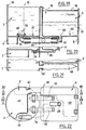
- the reserve device is adapted to receive a fuel pump 40 of a conventional type extending in part in main bowl 2, suitable for pumping fuel contained in the main bowl 2, or even reject in this bowl fuel not consumed by the engine.
- the maneuvers described with reference to the figures 12 to 17 can be executed with pump 40 already at less partially arranged in the main bowl 2.
- each bowls 2, 4 has a bottom 42, 44 with several levels, presenting a single zone 46, 48 the most close to the base, that is to say the lowest. Each bottom is shaped to allow the flow of fuel into the bowl by gravity towards this lowest zone 46, 48. The two zones 46, 48 extend at the same height in an unsolicited position legs 20, 22.
- Each bowl 2, 4 has a tubular mouthpiece 50, 52 integrally with the bowl and communicating towards the outside of the bowl with this area the lowest, the axis of the mouth being at the same height than the associated zone 46, 48. Both mouthpieces 50, 52 each have an "L" shape and are generally symmetrical to each other with respect to the axis of articulation 30.
- these mouths have mutually coaxial sections extending in the direction from each other and parallel sections between them.
- the two mouths 50, 52 extend as low as possible and as close as possible to one of the other.
- the device has a flexible conduit flexible 54 connected to the two mouths 50, 52 and putting these in fluid communication.
- the conduit 54 has a median section curved into an arc spanning three-quarters of a turn. Its axis extends in being parallel to bases 6, 8 of the bowls in the non-position solicited legs.
- the axis 30 of the joint serves of axis of symmetry to conduit 54. This arrangement of the conduit 54 allows it not to hinder maneuvers for introducing the reserve device into the tank. In particular, the duct 54 then bends around axis 30.
- the device comprises a non-return valve 55, shown schematically in Figures 1, 10 and 11, associated with conduit 54 at the mouth 50 of the main bowl 2.
- This valve 55 is arranged so that the main bowl 2 can be supplied with fuel from of the auxiliary bowl 4 via the conduit 54, as indicated by arrow 56 in Figure 1, but not vice versa.
- the feeding of the bowl is prohibited auxiliary 4 by the main bowl 2 via the conduit 54.
- This feeding of the main bowl 2 by the bowl auxiliary 4 is done automatically when the level of fuel in the main bowl 2 becomes less than the one in the auxiliary bowl 4.
- the upper opening 18 of the auxiliary bowl 4 extends in the vicinity of the main bowl 2. It is contiguous to the edge 34 cooperating with the lug 32. In addition, the edge 14 of the main bowl 2 has its lowest zone 56 extending over lug 34. This arrangement allows the supply of the auxiliary bowl 4 from the main bowl 2 by overflow thereof, over area 56 and through opening 18 as indicated by arrow 60 in FIG. 1, for example due to the vehicle movements.
- Main bowl 2 overflows continuously as long as it there is gasoline in the tank around the device reserve. So there is a permanent transfer of fuel from main bowl 2 to auxiliary bowl 4 to through the opening 18, and a fuel flow auxiliary bowl 4 to main bowl 2 to through valve 55. This ensures self-cleaning of the valve.
- the device comprises, not shown in detail and known per se, a filling member 69 of the main bowl 2 in fuel.
- the device includes besides a strainer forming a filter 61 clipped under the bottom of main bowl 2 and in fluid communication with this member 69 according to the arrow 71 of FIG. 1 and with the fuel tank according to arrow 63.
- This member 69 can be the first stage of a double stage pump, a jet pump, or the like.
- the filling member 69 supplies the main bowl 2 with fuel from the tank through the strainer 61.
- the main bowl 2 possibly includes a conduit 64 communicating with the strainer 61 and fitted at one end with a filter 66, serving here as an extension filter.
- Filter 66 extends under the auxiliary bowl 4. Filter 66 allows increase the filtering area and capture gasoline in other areas of the tank away from the main bowl 2. However, communication between the main bowl 2 and the tank could alternately be do with this one filter 66.
- the diagram in figure 18 illustrates this flow of fuel.
- Figure 10 shows different situations of the fuel level in the woods 2, 4 when the tank 36 undergoes, due to the movement of the vehicle, a acceleration parallel to the axis 12 of the auxiliary bowl 4 and directed from the main bowl 2 to the auxiliary bowl 4, as shown by arrow 63.
- this is acceleration to the left if the main bowl 2 is arranged to the left of the auxiliary bowl 4 in the vehicle. It is considered here that the fuel tank 36 is then almost completely empty, the reserve containing the only remaining fuel. Level fuel is then oriented according to this acceleration and gravity.
- the fuel passes into the bowl main 2 from level 70 to level 72 which cuts geometrically the upper edge 56 of the main bowl.
- the fuel in the main bowl can then be used by the pump 40 as long as its level 74 is between levels 72 and 76, the latter being close to the valve non-return 55.
- the auxiliary bowl 4 can feed the bowl main 2 through conduit 54 as long as the level in the auxiliary bowl 4 does not reach level 78 where it passes below the valve.
- the acceleration is this time facing in the opposite direction, to the right, as shown in arrow 65.
- the auxiliary bowl 4 overflows, especially towards the main bowl 2, until reach level 80 passing geometrically through the upper edge 56.
- the remaining fuel part can then pass entirely into the main bowl 2 via the conduit 54.
- the fuel overflows to the left until you reach level 84 passing geometrically through the upper edge 14 of the bowl principal 2. Almost the entire contents of the bowl main 2 can then be pumped.
- the pump 40 can be powered by almost all of the main bowl 2 and an important part of the auxiliary bowl 4.
- the amount of fuel actually usable by the pump can be further increased by providing the bowl main 2 of a cover, for example open on the right towards auxiliary bowl 4 to continue allow the aforementioned overflow.
- Figures 19 to 22 show a second mode of realization of the device of the invention.
- the legs 20, 22 are identical between they. They are arranged on either side of a plane common median longitudinal of the bowls passing through their axes 10, 12.
- the duct 54 has an "S" shape, the mouths 50, 52 of the bowls associated with this conduit communicating with a central zone of the bottom 42, 44 of each bowl.
- the axis of articulation 30 defined by the legs 20, 22 pass through a central section of the conduit 54 in "S".
- connection between the bowls 2, 4 may include a relative sliding of the bowls.
Landscapes
- Engineering & Computer Science (AREA)
- Life Sciences & Earth Sciences (AREA)
- Sustainable Development (AREA)
- Sustainable Energy (AREA)
- Chemical & Material Sciences (AREA)
- Combustion & Propulsion (AREA)
- Transportation (AREA)
- Mechanical Engineering (AREA)
- Cooling, Air Intake And Gas Exhaust, And Fuel Tank Arrangements In Propulsion Units (AREA)
Applications Claiming Priority (2)
| Application Number | Priority Date | Filing Date | Title |
|---|---|---|---|
| FR9715619 | 1997-12-10 | ||
| FR9715619A FR2771972B1 (fr) | 1997-12-10 | 1997-12-10 | Dispositif de reserve pour un reservoir de carburant de vehicule automobile |
Publications (2)
| Publication Number | Publication Date |
|---|---|
| EP0922603A1 true EP0922603A1 (de) | 1999-06-16 |
| EP0922603B1 EP0922603B1 (de) | 2002-09-04 |
Family
ID=9514406
Family Applications (1)
| Application Number | Title | Priority Date | Filing Date |
|---|---|---|---|
| EP19980403101 Expired - Lifetime EP0922603B1 (de) | 1997-12-10 | 1998-12-09 | Vorratsbehälter für den Kraftstofftank eines Kraftfahrzeuges |
Country Status (3)
| Country | Link |
|---|---|
| EP (1) | EP0922603B1 (de) |
| DE (1) | DE69807637T2 (de) |
| FR (1) | FR2771972B1 (de) |
Cited By (13)
| Publication number | Priority date | Publication date | Assignee | Title |
|---|---|---|---|---|
| WO2000056564A1 (de) * | 1999-03-20 | 2000-09-28 | Kautex Textron Gmbh. & Co. Kg. | Kraftstofftank für ein kraftfahrzeug |
| EP1162100A2 (de) | 2000-06-08 | 2001-12-12 | Kautex Textron GmbH & Co. KG. | Kraftstoffördereinheit |
| WO2002103196A1 (de) * | 2001-06-19 | 2002-12-27 | Robert Bosch Gmbh | Kraftstoffversorgungseinrichtung für ein kraftfahrzeug |
| EP1238846A3 (de) * | 2001-01-03 | 2004-03-24 | Siemens Aktiengesellschaft | Einrichtung zur Sammlung von Kraftstoff |
| EP1577145A1 (de) * | 2004-03-17 | 2005-09-21 | Delphi Technologies, Inc. | Behälter- und Filteranordnung |
| WO2007003526A1 (de) * | 2005-07-04 | 2007-01-11 | Siemens Vdo Automotive Ag | Vorrichtung zum fördern von kraftstoff aus einem kraftstoff-behälter |
| WO2007026011A1 (en) * | 2005-09-02 | 2007-03-08 | Inergy Automotive Systems Research (Société Anonyme) | Fuel system comprising a fuel reserve container and a retaining trough |
| DE10161403B4 (de) * | 2001-12-13 | 2007-03-29 | Siemens Ag | Kraftstofffördereinheit |
| EP1916145A1 (de) * | 2006-10-27 | 2008-04-30 | Delphi Technologies, Inc. | Kraftstoffmodul für einen blaßgeformten Tank und Verfahren zu dessen Einbau |
| JP2008121516A (ja) * | 2006-11-10 | 2008-05-29 | Aisan Ind Co Ltd | 燃料ポンプユニット、燃料ポンプモジュール及び燃料供給装置並びにこれらのいずれかを備えた燃料タンクユニット |
| JP2010236409A (ja) * | 2009-03-31 | 2010-10-21 | Denso Corp | 燃料供給装置 |
| EP1990226A4 (de) * | 2006-02-28 | 2012-04-18 | Nifco Inc | Schalldämpfungsvorrichtung und befestigungsverfahren dafür |
| RU2623332C2 (ru) * | 2012-04-25 | 2017-06-23 | ФОРД ГЛОУБАЛ ТЕКНОЛОДЖИЗ, ЭлЭлСи | Модуль подачи топлива |
Families Citing this family (5)
| Publication number | Priority date | Publication date | Assignee | Title |
|---|---|---|---|---|
| DE10356965A1 (de) * | 2003-12-05 | 2005-07-28 | Siemens Ag | Fördereinheit zu Förderung von Kraftstoff aus einem Kraftstoffbehälter |
| FR2875858B1 (fr) | 2004-09-28 | 2010-10-22 | Marwal Systems | Ensemble compose d'un module de puisage et d'un accessoire, inserable dans un reservoir de carburant de vehicule automobile |
| FR2875859B1 (fr) | 2004-09-28 | 2011-05-06 | Marwal Systems | Dispositif porte-accessoires pour module de puisage du reservoir d'un vehicule automobile |
| US7556024B2 (en) | 2005-09-22 | 2009-07-07 | Ti Group Automotive Systems, L.L.C. | Fuel supply module |
| DE102007032271A1 (de) * | 2007-07-11 | 2009-01-15 | Continental Automotive Gmbh | Kraftstofffördereinheit |
Citations (3)
| Publication number | Priority date | Publication date | Assignee | Title |
|---|---|---|---|---|
| FR2525162A1 (fr) * | 1982-04-16 | 1983-10-21 | Techni Plaste Sa | Recipient rigide, d'une seule piece, a ouverture plus grande que le fond et resserrable elastiquement |
| EP0798458A1 (de) * | 1996-03-27 | 1997-10-01 | Bitron France | In den Tank eines Kraftfahrzeuges eingetauchte Pumpvorrichtung |
| FR2746855A1 (fr) | 1996-03-28 | 1997-10-03 | Marwal Systems | Dispositif de pompage de carburant pour reservoir multipoches |
-
1997
- 1997-12-10 FR FR9715619A patent/FR2771972B1/fr not_active Expired - Fee Related
-
1998
- 1998-12-09 EP EP19980403101 patent/EP0922603B1/de not_active Expired - Lifetime
- 1998-12-09 DE DE1998607637 patent/DE69807637T2/de not_active Expired - Lifetime
Patent Citations (3)
| Publication number | Priority date | Publication date | Assignee | Title |
|---|---|---|---|---|
| FR2525162A1 (fr) * | 1982-04-16 | 1983-10-21 | Techni Plaste Sa | Recipient rigide, d'une seule piece, a ouverture plus grande que le fond et resserrable elastiquement |
| EP0798458A1 (de) * | 1996-03-27 | 1997-10-01 | Bitron France | In den Tank eines Kraftfahrzeuges eingetauchte Pumpvorrichtung |
| FR2746855A1 (fr) | 1996-03-28 | 1997-10-03 | Marwal Systems | Dispositif de pompage de carburant pour reservoir multipoches |
Cited By (20)
| Publication number | Priority date | Publication date | Assignee | Title |
|---|---|---|---|---|
| US6606980B1 (en) | 1999-03-20 | 2003-08-19 | Kautex Textron Gmbh & Co. Kg | Fuel tank for a motor vehicle |
| WO2000056564A1 (de) * | 1999-03-20 | 2000-09-28 | Kautex Textron Gmbh. & Co. Kg. | Kraftstofftank für ein kraftfahrzeug |
| EP1162100A2 (de) | 2000-06-08 | 2001-12-12 | Kautex Textron GmbH & Co. KG. | Kraftstoffördereinheit |
| US6640832B2 (en) | 2000-06-08 | 2003-11-04 | Kautex Textron Gmbh & Co. Kg | Fuel delivery unit |
| DE10027991B4 (de) * | 2000-06-08 | 2005-11-10 | Kautex Textron Gmbh & Co. Kg | Kraftstofffördereinheit |
| EP1162100A3 (de) * | 2000-06-08 | 2006-04-19 | Kautex Textron GmbH & Co. KG. | Kraftstoffördereinheit |
| EP1238846A3 (de) * | 2001-01-03 | 2004-03-24 | Siemens Aktiengesellschaft | Einrichtung zur Sammlung von Kraftstoff |
| WO2002103196A1 (de) * | 2001-06-19 | 2002-12-27 | Robert Bosch Gmbh | Kraftstoffversorgungseinrichtung für ein kraftfahrzeug |
| DE10161403B4 (de) * | 2001-12-13 | 2007-03-29 | Siemens Ag | Kraftstofffördereinheit |
| EP1577145A1 (de) * | 2004-03-17 | 2005-09-21 | Delphi Technologies, Inc. | Behälter- und Filteranordnung |
| CN101218120A (zh) * | 2005-07-04 | 2008-07-09 | 西门子威迪欧汽车电子股份公司 | 用于将燃料输送出燃料箱的装置 |
| WO2007003526A1 (de) * | 2005-07-04 | 2007-01-11 | Siemens Vdo Automotive Ag | Vorrichtung zum fördern von kraftstoff aus einem kraftstoff-behälter |
| US7861695B2 (en) | 2005-07-04 | 2011-01-04 | Continental Automotive Gmbh | Device for delivering fuel out of a fuel tank |
| FR2890341A1 (fr) * | 2005-09-02 | 2007-03-09 | Inergy Automotive Systems Res | Systeme a carburant comprenant une reserve a carburant et un bac de retention |
| WO2007026011A1 (en) * | 2005-09-02 | 2007-03-08 | Inergy Automotive Systems Research (Société Anonyme) | Fuel system comprising a fuel reserve container and a retaining trough |
| EP1990226A4 (de) * | 2006-02-28 | 2012-04-18 | Nifco Inc | Schalldämpfungsvorrichtung und befestigungsverfahren dafür |
| EP1916145A1 (de) * | 2006-10-27 | 2008-04-30 | Delphi Technologies, Inc. | Kraftstoffmodul für einen blaßgeformten Tank und Verfahren zu dessen Einbau |
| JP2008121516A (ja) * | 2006-11-10 | 2008-05-29 | Aisan Ind Co Ltd | 燃料ポンプユニット、燃料ポンプモジュール及び燃料供給装置並びにこれらのいずれかを備えた燃料タンクユニット |
| JP2010236409A (ja) * | 2009-03-31 | 2010-10-21 | Denso Corp | 燃料供給装置 |
| RU2623332C2 (ru) * | 2012-04-25 | 2017-06-23 | ФОРД ГЛОУБАЛ ТЕКНОЛОДЖИЗ, ЭлЭлСи | Модуль подачи топлива |
Also Published As
| Publication number | Publication date |
|---|---|
| EP0922603B1 (de) | 2002-09-04 |
| FR2771972B1 (fr) | 2000-02-25 |
| FR2771972A1 (fr) | 1999-06-11 |
| DE69807637D1 (de) | 2002-10-10 |
| DE69807637T2 (de) | 2003-05-28 |
Similar Documents
| Publication | Publication Date | Title |
|---|---|---|
| EP0922603B1 (de) | Vorratsbehälter für den Kraftstofftank eines Kraftfahrzeuges | |
| EP3239581A1 (de) | Verschlussschieber für fluid-anschluss | |
| EP2670229B1 (de) | Bewässerungsvorrichtung zum einsatz in einen zuchtbehälter mit einem unabhängigen reservoir | |
| EP0199643A2 (de) | Reservoirverschluss | |
| EP0721071B1 (de) | Verbesserungen in vibrationsdämpfenden hydraulischen Stützen | |
| FR2687456A1 (fr) | Projecteur equipe de moyens de ventilation perfectionnes, notamment pour vehicule automobile. | |
| WO1999043977A1 (fr) | Raccord encliquetable pour conduit de fluide | |
| EP0760306B1 (de) | Tankklappe | |
| FR2792620A1 (fr) | Support de poche souple et distributeur comprenant un tel support | |
| EP3795500B1 (de) | Abgedichteter deckel für einen abfallsammelbehälter | |
| FR3100587A1 (fr) | Dispositif de fixation et systeme comportant ce dispositif de fixation | |
| FR2952151A1 (fr) | Systeme de montage d'une extremite libre d'une tige de commande dans une cage | |
| EP1125865B1 (de) | Tank mit Mannloch sowie Tankfahrzeug mit einem solchen Tank | |
| FR2817454A1 (fr) | Meuble pour element tel qu'evier ou vasque | |
| FR3080091A1 (fr) | Embarcation gonflable comportant un organe de flottaison, une unite de direction et une unite de propulsion | |
| EP1158634A2 (de) | Endstück für den Führungskanal elektrischer Leiter oder Kabel | |
| FR2653652A1 (fr) | Bassin d'aisances a sachet de proprete. | |
| FR2699045A1 (fr) | Récipient pour plantes. | |
| WO2008017774A1 (fr) | Ouvrant de vehicule automobile comprenant un raidisseur et vehicule muni un tel ouvrant | |
| FR2791945A1 (fr) | Porte-bidon pour bicyclette | |
| EP4260780A1 (de) | Staubsaugermundstück mit nassreinigungsvorrichtung | |
| FR2743479A1 (fr) | Porte-bouteilles | |
| EP4260783A1 (de) | Staubsaugermundstück mit nassreinigungsvorrichtung | |
| FR3055862A1 (fr) | Adaptateur pour la connexion d'un balai d'essuyage a un bras d'entrainement d'un systeme d'essuyage pour vehicule automobile | |
| FR2760577A1 (fr) | Motoreducteur d'essuie-glace de vehicule automobile comportant un respirateur sans effet siphon |
Legal Events
| Date | Code | Title | Description |
|---|---|---|---|
| PUAI | Public reference made under article 153(3) epc to a published international application that has entered the european phase |
Free format text: ORIGINAL CODE: 0009012 |
|
| AK | Designated contracting states |
Kind code of ref document: A1 Designated state(s): DE ES GB IT SE |
|
| AX | Request for extension of the european patent |
Free format text: AL;LT;LV;MK;RO;SI |
|
| 17P | Request for examination filed |
Effective date: 19991215 |
|
| AKX | Designation fees paid |
Free format text: DE ES GB IT SE |
|
| GRAG | Despatch of communication of intention to grant |
Free format text: ORIGINAL CODE: EPIDOS AGRA |
|
| 17Q | First examination report despatched |
Effective date: 20011120 |
|
| GRAG | Despatch of communication of intention to grant |
Free format text: ORIGINAL CODE: EPIDOS AGRA |
|
| GRAH | Despatch of communication of intention to grant a patent |
Free format text: ORIGINAL CODE: EPIDOS IGRA |
|
| GRAH | Despatch of communication of intention to grant a patent |
Free format text: ORIGINAL CODE: EPIDOS IGRA |
|
| GRAA | (expected) grant |
Free format text: ORIGINAL CODE: 0009210 |
|
| AK | Designated contracting states |
Kind code of ref document: B1 Designated state(s): DE ES GB IT SE |
|
| PG25 | Lapsed in a contracting state [announced via postgrant information from national office to epo] |
Ref country code: IT Free format text: LAPSE BECAUSE OF FAILURE TO SUBMIT A TRANSLATION OF THE DESCRIPTION OR TO PAY THE FEE WITHIN THE PRESCRIBED TIME-LIMIT;WARNING: LAPSES OF ITALIAN PATENTS WITH EFFECTIVE DATE BEFORE 2007 MAY HAVE OCCURRED AT ANY TIME BEFORE 2007. THE CORRECT EFFECTIVE DATE MAY BE DIFFERENT FROM THE ONE RECORDED. Effective date: 20020904 Ref country code: GB Free format text: LAPSE BECAUSE OF FAILURE TO SUBMIT A TRANSLATION OF THE DESCRIPTION OR TO PAY THE FEE WITHIN THE PRESCRIBED TIME-LIMIT Effective date: 20020904 |
|
| REG | Reference to a national code |
Ref country code: GB Ref legal event code: FG4D Free format text: NOT ENGLISH |
|
| REF | Corresponds to: |
Ref document number: 69807637 Country of ref document: DE Date of ref document: 20021010 |
|
| PG25 | Lapsed in a contracting state [announced via postgrant information from national office to epo] |
Ref country code: SE Free format text: LAPSE BECAUSE OF FAILURE TO SUBMIT A TRANSLATION OF THE DESCRIPTION OR TO PAY THE FEE WITHIN THE PRESCRIBED TIME-LIMIT Effective date: 20021204 |
|
| GBV | Gb: ep patent (uk) treated as always having been void in accordance with gb section 77(7)/1977 [no translation filed] |
Effective date: 20020904 |
|
| PG25 | Lapsed in a contracting state [announced via postgrant information from national office to epo] |
Ref country code: ES Free format text: LAPSE BECAUSE OF FAILURE TO SUBMIT A TRANSLATION OF THE DESCRIPTION OR TO PAY THE FEE WITHIN THE PRESCRIBED TIME-LIMIT Effective date: 20030328 |
|
| PLBE | No opposition filed within time limit |
Free format text: ORIGINAL CODE: 0009261 |
|
| STAA | Information on the status of an ep patent application or granted ep patent |
Free format text: STATUS: NO OPPOSITION FILED WITHIN TIME LIMIT |
|
| 26N | No opposition filed |
Effective date: 20030605 |
|
| PGFP | Annual fee paid to national office [announced via postgrant information from national office to epo] |
Ref country code: DE Payment date: 20111229 Year of fee payment: 14 |
|
| REG | Reference to a national code |
Ref country code: DE Ref legal event code: R119 Ref document number: 69807637 Country of ref document: DE Effective date: 20130702 |
|
| PG25 | Lapsed in a contracting state [announced via postgrant information from national office to epo] |
Ref country code: DE Free format text: LAPSE BECAUSE OF NON-PAYMENT OF DUE FEES Effective date: 20130702 |