EP0922656B1 - Ensemble transporteur et méthode de transport de sachets - Google Patents
Ensemble transporteur et méthode de transport de sachets Download PDFInfo
- Publication number
- EP0922656B1 EP0922656B1 EP98310041A EP98310041A EP0922656B1 EP 0922656 B1 EP0922656 B1 EP 0922656B1 EP 98310041 A EP98310041 A EP 98310041A EP 98310041 A EP98310041 A EP 98310041A EP 0922656 B1 EP0922656 B1 EP 0922656B1
- Authority
- EP
- European Patent Office
- Prior art keywords
- conveyor
- bags
- belt
- plenum member
- air pressure
- Prior art date
- Legal status (The legal status is an assumption and is not a legal conclusion. Google has not performed a legal analysis and makes no representation as to the accuracy of the status listed.)
- Expired - Lifetime
Links
- 238000000034 method Methods 0.000 title claims description 13
- 230000002950 deficient Effects 0.000 claims description 4
- 238000004806 packaging method and process Methods 0.000 abstract description 10
- 238000012856 packing Methods 0.000 description 4
- 238000007789 sealing Methods 0.000 description 4
- 238000010276 construction Methods 0.000 description 2
- 235000013305 food Nutrition 0.000 description 2
- 238000013459 approach Methods 0.000 description 1
- 238000007689 inspection Methods 0.000 description 1
- 235000019684 potato crisps Nutrition 0.000 description 1
- 235000011888 snacks Nutrition 0.000 description 1
- 230000032258 transport Effects 0.000 description 1
Images


Classifications
-
- B—PERFORMING OPERATIONS; TRANSPORTING
- B65—CONVEYING; PACKING; STORING; HANDLING THIN OR FILAMENTARY MATERIAL
- B65G—TRANSPORT OR STORAGE DEVICES, e.g. CONVEYORS FOR LOADING OR TIPPING, SHOP CONVEYOR SYSTEMS OR PNEUMATIC TUBE CONVEYORS
- B65G21/00—Supporting or protective framework or housings for endless load-carriers or traction elements of belt or chain conveyors
- B65G21/20—Means incorporated in, or attached to, framework or housings for guiding load-carriers, traction elements or loads supported on moving surfaces
- B65G21/2027—Suction retaining means
- B65G21/2036—Suction retaining means for retaining the load on the load-carrying surface
Definitions
- the present invention relates in general to a conveyor assembly and a method of conveying items to be packaged such as packages containing a food product.
- USA Patents 3850780 and 4663917 are packaging machines which receive a product, deliver the product into a tubular bag material and then sever portions of the tubular bag material to form sealing closed bags of product. More particularly, the machine of USA Patent 4663917 is suited to packaging snack foods, such as potato crisps.
- the invention provides a method of conveying bags to be packaged, as recited in claim 1.
- the invention provides a conveyor assembly, adapted to perform the above method, said assembly comprising the features in claim 7.
- FIG. 1 there is schematically depicted a packaging machine 10, which can be the packaging machine of USA Patent 4663917.
- the packaging machine 10 has a product delivery chute 11 through which product is delivered to the interior of tubular bag material moved through the packaging machine 10 by drive belts 12.
- Individual bags 13 are formed by rotatably driven jaws 14, which form seals at the ends of each bag 13 and sever each bag 13 from the tubular bag material.
- the bags 13 are engaged and transported by a conveyor assembly 15 from a receiving end 43 to a delivery end 44.
- the conveyor assembly 15 includes a first conveyor 16.
- the conveyor 16 engages the bags 13 as they leave the jaws 14 and transports the bags 13 to a second conveyor 17.
- the conveyor 16 includes a first plenum member 18 which is connected to a means of reducing the air pressure within the plenum member 18.
- the plenum member 18 has an apertured portion 19 in the form of a downwardly facing plate with at least one longitudinally extending aperture (slot) 20.
- a conveyor belt 21 passes between two pairs of rollers 22 and 23 of which at least one pair is driven so that the rollers 22 and 23 rotate in the direction of the arrows 24.
- the belt 21 has a plurality of apertures 25 which are arranged in a row so that when passing the plate 20, they communicate with the slot 20. It should be particularly noted that the plenum member 18 has a curved portion 26 which includes a portion of the plate 19 and slot 20.
- the conveyor 16 includes a second plenum member 27.
- the plenum member 18 may merely extend to be adjacent to the rollers 23 so that a plenum member 27 is not required.
- the plenum member 27 is provided and is independently reduced in internal pressure.
- the plenum member 27 has a plate 28 passed by the belt 21, with the plate 28 having at least one longitudinal slot 29.
- the apertures 25 pass longitudinally of the slot 29.
- the conveyor 16 has its receiving end 43 adjacent to where the bags 13 are initially released by the sealing jaws 14.
- the bags 13 engage the end 43 and in particular are drawn into contact with the belt 21 due to the difference in pressure existing across the belt 25 as a result of a reduction in pressure internally of the plenum member 18.
- Each bag 13 will engage the belt 21 and close off one or more of the apertures 25 and therefore have air pressure exert a force on the bag 13 to pull it into contact with the belt 21 so that the bags 13 depend from the belt 27 adjacent to the apertured portion 19. Movement of the belt 21 will then convey the packages to the end 31 of the conveyor 16. If so required air pressure within the plenum member 27 may be varied and in particular may be governed so as to fluctuate.
- a bag may be drawn into contact with the belt 22 as it passes the plenum member 27 up until the package 13 approaches the conveyor 17.
- the pressure differential may be reduced to zero or as a further alternative may be raised above the surrounding air pressure so that the bag 13 adjacent the plate 28 is ejected from the conveyor 16.
- the conveyor 16 may be associated with a mechanism which detects defective bags 13. The defective bags 13 could then be ejected from the conveyor assembly 15 by increasing the pressure in the plenum member 27 so that the bag 13 located thereat is rejected and not passed to the conveyor 17.
- the conveyor 17 would then be controlled to compensate for the loss of the defective bag 13 in forming sets 39 of bags 13.
- the belt 21 is continuously driven past a location at which the bags 13 are released by the jaws 14 so that collection of the bags 13 by the assembly 15 is not intermittent.
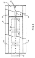
- the conveyor 17 is similar in construction to the conveyor 16 in that a first plenum member 30 is provided, which plenum member 30 has a downwardly facing apertured plate 40, provided with at least one longitudinally extending slot 32. Extending between pairs of rollers 33 and 34 is a belt 35 provided with a row of apertures 36. The apertures 36 pass longitudinally adjacent to the slot 32. A second plenum member 37 is also provided. The plenum member 37 has an aperture plate 38 provided with a longitudinally extending groove which communicates with the row of apertures 36.
- the plenum member 30 is provided with reduced pressure so that bags 13 are urged into contact with the belt 35 due to the pressure differential between the interior of the plenum member 30 and the exterior.
- the bags 13 would cover at least one of the apertures 36 so as to be urged into contact with the belt 35 so as to depend therefrom.
- the plenum member 38 may be provided with the same pressure as the plenum member 30 or alternatively may be pulsed so as to have no pressure differential or alternatively a positive pressure differential to eject the bags 13 from the conveyor 17.
- At least one of the pairs of rollers 33 or 34 is driven.
- the belt 35 is intermittently driven so that the bags 13 are arranged in sets of a predetermined number, with the belt accelerating and decelerating to provide a gap between the bag sets 39.
- the gap being larger than the space between adjacent bags 13 of each set 30 so that the sets can be distinguished.
- the conveyors 16 and 17 would be arranged so that the bags 13 when delivered to the conveyor 17, are oriented generally vertically so as to depend from the belt 35. To do this the upper portion of the bag would need to be drawn into contact with the belt 17 so that at least one of the apertures 36 was covered by the bag 13.
- the conveyor 16 engages the bags 13 so as to maintain them in a predetermined orientation. As the bags 13 pass the plate 19, they are maintained in a generally horizontal orientation. That is, the belt 21 engages a side wall 40 of each bag 13. This facilitates transfer of the bags 13 to the conveyor 17 which engages the leading end 41 of each bag 13. By engaging the leading end 41, the bags depend from the belt 35 so as to be oriented generally vertically. They therefore arrive at the end 42 of the conveyor 17 in sets of a predetermined number and at regular intervals and in a predetermined orientation. This greatly facilitates packaging into boxes and larger bags.
Landscapes
- Engineering & Computer Science (AREA)
- Mechanical Engineering (AREA)
- Auxiliary Devices For And Details Of Packaging Control (AREA)
- Supplying Of Containers To The Packaging Station (AREA)
- Formation And Processing Of Food Products (AREA)
- Escalators And Moving Walkways (AREA)
- Structure Of Belt Conveyors (AREA)
- Specific Conveyance Elements (AREA)
- Attitude Control For Articles On Conveyors (AREA)
- Delivering By Means Of Belts And Rollers (AREA)
- Belt Conveyors (AREA)
Claims (12)
- Procédé de transport de sachets (13) devant être conditionnés, ledit procédé comprenant les étapes de :fourniture d'un groupe desdits sachets ;suspension des sachets provenant d'un premier transporteur qui transporte les sachets provenant d'un emplacement de réception (43) à un emplacement de sortie (44), les sachets étant poussés pour entrer en contact avec le transporteur par pression d'air ;sortie des sachets de ladite extrémité de sortie vers un deuxième transporteur (17) ;suspension des sachets provenant du deuxième transporteur et transport des sachets d'une extrémité de sortie du deuxième transporteur, à laquelle les sachets sont reçus de l'extrémité de sortie du premier transporteur, vers un emplacement de sortie auquel les sachets sont retirés du deuxième transporteur, les sachets étant poussés pour entrer en contact avec le deuxième transporteur par pression d'air et dans lequella vitesse du premier et du deuxième transporteur intervient dans la disposition des sachets dans le deuxième transporteur de sorte que les sachets sont placés à des intervalles espacés en ensembles espacés (39), le premier espacement entre l'ensemble adjacent étant plus important que l'espacement entre les sachets à l'intérieur de chaque ensemble.
- Procédé selon la revendication 1, dans lequel le deuxième transporteur est accéléré et ralenti pour fournir l'espacement entre les ensembles adjacents.
- Procédé selon la revendication 1 ou 2, dans lequel les sachets sont disposés, d'une manière générale, horizontalement, lorsqu'ils sont mis en prise avec le premier transporteur, une paroi latérale (40) de chaque sachet étant poussée pour être mise en prise avec ce premier transporteur, et chaque sachet présente une partie d'extrémité (41) mise en prise avec le deuxième transporteur pour être suspendue verticalement par cette partie d'extrémité.
- Procédé selon la revendication 1 ou 2, dans lequel les sachets sont soumis à une variation de pression d'air à l'extrémité de sortie dudit premier transporteur pour aider au retrait des sachets provenant du premier transporteur.
- Procédé selon la revendication 4, dans lequel les sachets défectueux sont dégagés de l'extrémité de sortie du premier transporteur en réduisant la pression d'air.
- Procédé selon la revendication 4, dans lequel le transfert des sachets du premier transporteur au deuxième transporteur est facilité en réduisant la pression d'air poussant les sachets pour qu'ils entrent en contact avec le premier transporteur à ladite extrémité de sortie dudit premier transporteur.
- Ensemble transporteur (15), adapté pour exécuter le procédé de l'une quelconque des revendications 1 à 6, ledit ensemble comprenant :caractérisé en ce que l'ensemble transporteur (15) comprend, en outre, des moyens d'entraínement pour entraíner, par intermittence, la bande transporteuse (35) du deuxième transporteur (17) de sorte que les sachets (13) sont disposés sur ledit deuxième transporteur (17) en ensembles espacés, chaque ensemble comprenant une pluralité de sachets (13).un premier transporteur (16) comprenant :un élément formant chambre de répartition d'air (18) présentant une pression d'air interne réduite et une partie ouverte (19) orientée vers le bas avec une ouverture (20) ; etune première bande transporteuse (21) passant de manière adjacente sous la partie ouverte (19), la bande présentant des ouvertures (25) qui communiquent avec ladite ouverture (20) de ladite partie ouverte(19) de sorte que les sachets (13) en train d'être transportés par le premier transporteur (16) sont poussés pour être mis en prise avec la bande (21) par la différence de pression d'air entre l'intérieur et l'extérieur de l'élément formant chambre de répartition d'air (18),un deuxième transporteur (17) placé de manière adjacente au premier transporteur pour recevoir les sachets provenant de ce premier transporteur, le deuxième transporteur (17) comprenant ;un élément formant chambre de répartition d'air (30) ayant une pression d'air interne réduite, l'élément formant chambre de répartition d'air présentant une partie ouverte (40) orientée vers le bas avec une ouverture (32) ; etune deuxième bande transporteuse (35) passant de manière adjacente sous la partie ouverte de l'élément formant chambre de répartition d'air du deuxième transporteur (17), la bande (35) du deuxième transporteur présentant des ouvertures (36) qui communiquent avec ladite ouverture de la partie ouverte de l'élément formant chambre de répartition d'air du deuxième transporteur de sorte que les sachets transportés par la bande du deuxième transporteur dépendent de cette deuxième bande transporteuse et sont poussés par la pression d'air de manière à entrer en contact avec la bande du deuxième transporteur lorsqu'ils sont en communication avec, au moins, une ouverture de la partie ouverte de l'élément formant chambre de répartition d'air du deuxième transporteur ; dans laquelle la vitesse du premier et du deuxième transporteur peut être contrôlée,
- Ensemble transporteur selon la revendication 7, dans lequel ledit premier transporteur comprend, en outre, une paire de rouleaux (22,23) entre lesquels la bande du premier transporteur passe d'une extrémité (43) de réception des sachets à une extrémité (44) de sortie des sachets, et la partie ouverte (19) du premier transporteur comprend une partie d'extrémité (26) courbée adjacente à ladite extrémité de réception du premier transporteur de sorte que les sachets sont mis en prise avec la bande du premier transporteur adjacent à ladite partie d'extrémité courbée.
- Ensemble transporteur selon la revendication 7 ou 8, dans lequel le deuxième transporteur (17) comprend, en outre, une paire de rouleaux (33, 34) entre lesquels la bande (35) du deuxième transporteur passe d'une extrémité de réception de sachets à un emplacement éloigné du deuxième transporteur, et la partie ouverte du deuxième transporteur comprend une partie courbée adjacente à l'extrémité de réception du dit deuxième transporteur de sorte que les sachets sont mis en prise avec la bande du deuxième transporteur adjacent à la portion d'extrémité du deuxième transporteur.
- Ensemble transporteur selon la revendication 9, dans lequel ladite bande transporteuse (35) du deuxième transporteur (17) est, par intermittence, entraínée pour fournir l'espacement entre les ouvertures (36) de la bande transporteuse du deuxième transporteur auquel les sachets (13) sont reçus de la première bande (21) de sorte que les sachets sont transportés horizontalement par ladite bande et verticalement par ladite deuxième bande.
- Ensemble transporteur selon l'une quelconque des revendications 7 à 10, dans lequel chaque partie ouverte (19, 40) du dit premier et deuxième transporteur (16, 17) comprend une rainure (20, 32) proposant une ouverture s'étendant dans le sens de la longueur parallèlement à la bande associée (21, 35), et chaque bande est proposée avec une pluralité de dites ouvertures (25, 36) qui se déplacent pour s'aligner avec la rainure de la bande associée, de sorte que les sachets sont poussés pour se mettre en prise avec la bande associée.
- Ensemble transporteur selon l'une quelconque des revendications 7 à 11, dans lequel :l'élément formant chambre de répartition d'air (18) du premier transporteur est un premier élément formant chambre de répartition d'air ;et ledit premier transporteur comprend, en outre, un deuxième élément formant chambre de répartition d'air (27) présentant une partie ouverte (28) pour communiquer avec les ouvertures de la bande transporteuse (21) du premier transporteur, de sorte que les sachets passent de l'élément adjacent formant chambre de répartition d'air au dit premier élément formant chambre de répartition d'air, de l'élément adjacent formant chambre de répartition d'air au dit deuxième élément formant chambre de répartition d'air pour être transférés de là au dit deuxième transporteur (17) ; et dans lequel :la pression d'air du dit deuxième élément formant chambre de répartition d'air est changée, de sorte que la pression d'air au départ pousse l'un des sachets adjacents pour qu'il entre en contact avec la première bande et est ensuite augmentée pour faciliter le transfert de l'un desdits sachets adjacents à ladite bande transporteuse du dit deuxième transporteur.
Applications Claiming Priority (2)
| Application Number | Priority Date | Filing Date | Title |
|---|---|---|---|
| AUPP0939A AUPP093997A0 (en) | 1997-12-12 | 1997-12-12 | A conveyor |
| AUPP093997 | 1997-12-12 |
Publications (3)
| Publication Number | Publication Date |
|---|---|
| EP0922656A2 EP0922656A2 (fr) | 1999-06-16 |
| EP0922656A3 EP0922656A3 (fr) | 2000-04-12 |
| EP0922656B1 true EP0922656B1 (fr) | 2003-03-12 |
Family
ID=3805221
Family Applications (1)
| Application Number | Title | Priority Date | Filing Date |
|---|---|---|---|
| EP98310041A Expired - Lifetime EP0922656B1 (fr) | 1997-12-12 | 1998-12-08 | Ensemble transporteur et méthode de transport de sachets |
Country Status (7)
| Country | Link |
|---|---|
| US (1) | US6164436A (fr) |
| EP (1) | EP0922656B1 (fr) |
| JP (1) | JPH11236110A (fr) |
| AT (1) | ATE234249T1 (fr) |
| AU (1) | AUPP093997A0 (fr) |
| DE (1) | DE69812050T2 (fr) |
| ES (1) | ES2190046T3 (fr) |
Cited By (1)
| Publication number | Priority date | Publication date | Assignee | Title |
|---|---|---|---|---|
| EP3747808A1 (fr) | 2019-06-05 | 2020-12-09 | G.D. S.p.A | Dispositif et procédé pour alimenter des flans dans une machine de transformation ultérieure |
Families Citing this family (12)
| Publication number | Priority date | Publication date | Assignee | Title |
|---|---|---|---|---|
| ES2220380T3 (es) * | 2000-03-13 | 2004-12-16 | Cavanna S.P.A. | Procedimiento y dispositivo para formar grupos de articulos en un sistema transportador, por ejemplo para instalaciones de empaquetado. |
| AUPR793801A0 (en) * | 2001-09-27 | 2001-10-18 | Industrial Conveying (Aust.) Pty Ltd | Conveyor assembly |
| AUPS061402A0 (en) * | 2002-02-19 | 2002-03-14 | Tna Australia Pty Limited | A device to aid packaging items |
| GB0222626D0 (en) * | 2002-09-30 | 2002-11-06 | Ishida Europ Ltd | Item handling method and apparatus |
| AU2003903509A0 (en) * | 2003-07-08 | 2003-07-24 | Tna Australia Pty Limited | A packaging machine former support |
| JP2005335715A (ja) * | 2004-05-24 | 2005-12-08 | Ishida Co Ltd | 不良品検出装置およびこれを備えた製袋包装システム |
| JP2008094427A (ja) * | 2006-10-12 | 2008-04-24 | Ishida Co Ltd | 製袋包装システム |
| GB2457490A (en) * | 2008-02-15 | 2009-08-19 | Wright Machinery Ltd | Tubular conveyor for conveying bagged foodstuff |
| JP5404286B2 (ja) * | 2009-09-30 | 2014-01-29 | ユニ・チャーム株式会社 | ウェブ搬送装置 |
| US8127915B2 (en) * | 2009-12-21 | 2012-03-06 | Martin's Famous Pastry Shoppe, Inc. | System and method for separating a cluster of interconnected food products |
| DE102011085534B4 (de) * | 2011-11-01 | 2013-07-04 | Hauni Maschinenbau Ag | Verfahren und Vorrichtung zum Vereinzeln und Einlegen von Objekten in einen Materialstrang der Tabak verarbeitenden Industrie |
| AU2016204893B2 (en) | 2015-07-20 | 2020-07-02 | Tna Australia Pty Limited | A slip conveyor |
Family Cites Families (13)
| Publication number | Priority date | Publication date | Assignee | Title |
|---|---|---|---|---|
| US3675761A (en) * | 1970-08-05 | 1972-07-11 | Liggett & Myers Inc | Automatic cigarette feed machine having a vacuum belt conveyor |
| US3850780A (en) | 1971-08-23 | 1974-11-26 | Fmc Corp | Extended dwell heat sealer |
| US3958683A (en) * | 1974-09-27 | 1976-05-25 | Midland-Ross Corporation | Conveyor system including article regrouping apparatus |
| US4142624A (en) * | 1977-08-29 | 1979-03-06 | Velten & Pulver, Inc. | Bread accumulator |
| NL8300839A (nl) * | 1983-03-08 | 1984-10-01 | Thomassen & Drijver | Inrichting voor het in voorafgekozen onderlinge posities leggen van kussenvormige zakjes. |
| US4620826A (en) * | 1984-03-02 | 1986-11-04 | Roberto Gonzales Barrera | Materials handling apparatus |
| US4663917A (en) | 1984-06-20 | 1987-05-12 | Taylor Alfred A | Packaging apparatus |
| JPS61178315A (ja) * | 1985-02-01 | 1986-08-11 | Rheon Autom Mach Co Ltd | 食品素材の移載装置 |
| US4773522A (en) * | 1985-02-12 | 1988-09-27 | Meyer Conveyair, Inc. | Vacuum deadplate |
| US4670935A (en) * | 1985-04-16 | 1987-06-09 | Feco Engineered Systems, Inc. | Wet vacuum system for two piece can lines |
| DE3662592D1 (en) * | 1985-06-26 | 1989-05-03 | Sig Schweiz Industrieges | Apparatus for separating articles being in contact with each other |
| GB2212127B (en) * | 1987-11-11 | 1991-07-10 | Bishopbarn Ltd | Package handling apparatus and method |
| IT1246631B (it) * | 1991-01-25 | 1994-11-24 | Gd Spa | Convogliatore di stabilizzazione di pacchetti di sigarette in uscita da una macchina impacchettatrice. |
-
1997
- 1997-12-12 AU AUPP0939A patent/AUPP093997A0/en not_active Abandoned
-
1998
- 1998-12-08 US US09/207,565 patent/US6164436A/en not_active Expired - Lifetime
- 1998-12-08 DE DE69812050T patent/DE69812050T2/de not_active Expired - Fee Related
- 1998-12-08 EP EP98310041A patent/EP0922656B1/fr not_active Expired - Lifetime
- 1998-12-08 AT AT98310041T patent/ATE234249T1/de not_active IP Right Cessation
- 1998-12-08 ES ES98310041T patent/ES2190046T3/es not_active Expired - Lifetime
- 1998-12-11 JP JP10352883A patent/JPH11236110A/ja not_active Ceased
Cited By (1)
| Publication number | Priority date | Publication date | Assignee | Title |
|---|---|---|---|---|
| EP3747808A1 (fr) | 2019-06-05 | 2020-12-09 | G.D. S.p.A | Dispositif et procédé pour alimenter des flans dans une machine de transformation ultérieure |
Also Published As
| Publication number | Publication date |
|---|---|
| ATE234249T1 (de) | 2003-03-15 |
| DE69812050T2 (de) | 2003-10-30 |
| DE69812050D1 (de) | 2003-04-17 |
| AUPP093997A0 (en) | 1998-01-08 |
| US6164436A (en) | 2000-12-26 |
| ES2190046T3 (es) | 2003-07-16 |
| EP0922656A3 (fr) | 2000-04-12 |
| JPH11236110A (ja) | 1999-08-31 |
| EP0922656A2 (fr) | 1999-06-16 |
Similar Documents
| Publication | Publication Date | Title |
|---|---|---|
| EP0922656B1 (fr) | Ensemble transporteur et méthode de transport de sachets | |
| EP0485782B1 (fr) | Machine d'emballage automatique, ainsi que le procédé et le sac flexible obtenu | |
| US6182814B1 (en) | Inline vacuum slug feeder | |
| US4991708A (en) | Apparatus for forming groups of articles, particularly for automatic packaging lines | |
| US6711880B2 (en) | Apparatus for, and method of, feeding piece goods to a tubular-bag packaging station | |
| US4443995A (en) | Metering device and method | |
| CN106414280A (zh) | 上包输送带 | |
| EP0232439B1 (fr) | Machine d'emballage | |
| US5555700A (en) | Bottle conveying system | |
| WO1996032348A1 (fr) | Appareil de transfert avec lacher direct | |
| US5803702A (en) | Vision inspection system for double stacked packs | |
| US6205237B1 (en) | Method and device for the opto-electrical scanning of packets, especially cigarette packets | |
| EP0957028A1 (fr) | Procédé pour l'emballage d' articles dans des récipients | |
| JPH0761563A (ja) | 円錐形物品の供給装置 | |
| WO2022159465A1 (fr) | Bande transporteuse pour transporter un matériau transporté et ligne d'emballage d'un système d'emballage comprenant une telle bande transporteuse | |
| AU747764B2 (en) | A conveyor | |
| EP0941929B1 (fr) | Système d'inspection visuelle pour paquets empilés sur deux rangées | |
| US6898922B2 (en) | Method and device for the packaging of flat objects | |
| JP3995748B2 (ja) | 袋詰品の箱詰め方法 | |
| KR102748709B1 (ko) | 물품 분산 공급을 위한 장비를 구비한 물품 포장 시스템 | |
| JPH0761410A (ja) | 円錐体の箱詰め機 | |
| US6267224B1 (en) | Apparatus for separating and orienting pouched articles | |
| JP4570415B2 (ja) | コンベヤ装置用の整列方法及び整列装置 | |
| JP4887401B2 (ja) | 多列分配装置 | |
| US4702471A (en) | Article transport arrangement |
Legal Events
| Date | Code | Title | Description |
|---|---|---|---|
| PUAI | Public reference made under article 153(3) epc to a published international application that has entered the european phase |
Free format text: ORIGINAL CODE: 0009012 |
|
| AK | Designated contracting states |
Kind code of ref document: A2 Designated state(s): AT BE CH CY DE DK ES FI FR GB GR IE IT LI LU MC NL PT SE |
|
| AX | Request for extension of the european patent |
Free format text: AL;LT;LV;MK;RO;SI |
|
| PUAL | Search report despatched |
Free format text: ORIGINAL CODE: 0009013 |
|
| AK | Designated contracting states |
Kind code of ref document: A3 Designated state(s): AT BE CH CY DE DK ES FI FR GB GR IE IT LI LU MC NL PT SE |
|
| AX | Request for extension of the european patent |
Free format text: AL;LT;LV;MK;RO;SI |
|
| 17P | Request for examination filed |
Effective date: 20000916 |
|
| AKX | Designation fees paid |
Free format text: AT BE CH CY DE DK ES FI FR GB GR IE IT LI LU MC NL PT SE |
|
| AXX | Extension fees paid |
Free format text: AL PAYMENT 20000916;LT PAYMENT 20000916;LV PAYMENT 20000916;MK PAYMENT 20000916;RO PAYMENT 20000916;SI PAYMENT 20000916 |
|
| 17Q | First examination report despatched |
Effective date: 20010216 |
|
| GRAG | Despatch of communication of intention to grant |
Free format text: ORIGINAL CODE: EPIDOS AGRA |
|
| RTI1 | Title (correction) |
Free format text: A CONVEYOR ASSEMBLY AND A METHOD OF CONVEYING BAGS |
|
| GRAG | Despatch of communication of intention to grant |
Free format text: ORIGINAL CODE: EPIDOS AGRA |
|
| GRAH | Despatch of communication of intention to grant a patent |
Free format text: ORIGINAL CODE: EPIDOS IGRA |
|
| GRAH | Despatch of communication of intention to grant a patent |
Free format text: ORIGINAL CODE: EPIDOS IGRA |
|
| GRAA | (expected) grant |
Free format text: ORIGINAL CODE: 0009210 |
|
| AK | Designated contracting states |
Designated state(s): AT BE CH CY DE DK ES FI FR GB GR IE IT LI LU MC NL PT SE |
|
| AX | Request for extension of the european patent |
Extension state: AL LT LV MK RO SI |
|
| PG25 | Lapsed in a contracting state [announced via postgrant information from national office to epo] |
Ref country code: NL Free format text: LAPSE BECAUSE OF FAILURE TO SUBMIT A TRANSLATION OF THE DESCRIPTION OR TO PAY THE FEE WITHIN THE PRESCRIBED TIME-LIMIT Effective date: 20030312 Ref country code: LI Free format text: LAPSE BECAUSE OF FAILURE TO SUBMIT A TRANSLATION OF THE DESCRIPTION OR TO PAY THE FEE WITHIN THE PRESCRIBED TIME-LIMIT Effective date: 20030312 Ref country code: GR Free format text: LAPSE BECAUSE OF FAILURE TO SUBMIT A TRANSLATION OF THE DESCRIPTION OR TO PAY THE FEE WITHIN THE PRESCRIBED TIME-LIMIT Effective date: 20030312 Ref country code: FR Free format text: LAPSE BECAUSE OF FAILURE TO SUBMIT A TRANSLATION OF THE DESCRIPTION OR TO PAY THE FEE WITHIN THE PRESCRIBED TIME-LIMIT Effective date: 20030312 Ref country code: FI Free format text: LAPSE BECAUSE OF FAILURE TO SUBMIT A TRANSLATION OF THE DESCRIPTION OR TO PAY THE FEE WITHIN THE PRESCRIBED TIME-LIMIT Effective date: 20030312 Ref country code: CH Free format text: LAPSE BECAUSE OF FAILURE TO SUBMIT A TRANSLATION OF THE DESCRIPTION OR TO PAY THE FEE WITHIN THE PRESCRIBED TIME-LIMIT Effective date: 20030312 Ref country code: BE Free format text: LAPSE BECAUSE OF FAILURE TO SUBMIT A TRANSLATION OF THE DESCRIPTION OR TO PAY THE FEE WITHIN THE PRESCRIBED TIME-LIMIT Effective date: 20030312 Ref country code: AT Free format text: LAPSE BECAUSE OF FAILURE TO SUBMIT A TRANSLATION OF THE DESCRIPTION OR TO PAY THE FEE WITHIN THE PRESCRIBED TIME-LIMIT Effective date: 20030312 |
|
| REG | Reference to a national code |
Ref country code: GB Ref legal event code: FG4D |
|
| REG | Reference to a national code |
Ref country code: CH Ref legal event code: EP |
|
| REG | Reference to a national code |
Ref country code: IE Ref legal event code: FG4D |
|
| REF | Corresponds to: |
Ref document number: 69812050 Country of ref document: DE Date of ref document: 20030417 Kind code of ref document: P |
|
| PG25 | Lapsed in a contracting state [announced via postgrant information from national office to epo] |
Ref country code: SE Free format text: LAPSE BECAUSE OF FAILURE TO SUBMIT A TRANSLATION OF THE DESCRIPTION OR TO PAY THE FEE WITHIN THE PRESCRIBED TIME-LIMIT Effective date: 20030612 Ref country code: PT Free format text: LAPSE BECAUSE OF FAILURE TO SUBMIT A TRANSLATION OF THE DESCRIPTION OR TO PAY THE FEE WITHIN THE PRESCRIBED TIME-LIMIT Effective date: 20030612 Ref country code: DK Free format text: LAPSE BECAUSE OF FAILURE TO SUBMIT A TRANSLATION OF THE DESCRIPTION OR TO PAY THE FEE WITHIN THE PRESCRIBED TIME-LIMIT Effective date: 20030612 |
|
| REG | Reference to a national code |
Ref country code: ES Ref legal event code: FG2A Ref document number: 2190046 Country of ref document: ES Kind code of ref document: T3 |
|
| NLV1 | Nl: lapsed or annulled due to failure to fulfill the requirements of art. 29p and 29m of the patents act | ||
| LTIE | Lt: invalidation of european patent or patent extension |
Effective date: 20030312 |
|
| REG | Reference to a national code |
Ref country code: CH Ref legal event code: PL |
|
| PG25 | Lapsed in a contracting state [announced via postgrant information from national office to epo] |
Ref country code: LU Free format text: LAPSE BECAUSE OF NON-PAYMENT OF DUE FEES Effective date: 20031208 Ref country code: IE Free format text: LAPSE BECAUSE OF NON-PAYMENT OF DUE FEES Effective date: 20031208 Ref country code: CY Free format text: LAPSE BECAUSE OF FAILURE TO SUBMIT A TRANSLATION OF THE DESCRIPTION OR TO PAY THE FEE WITHIN THE PRESCRIBED TIME-LIMIT Effective date: 20031208 |
|
| PG25 | Lapsed in a contracting state [announced via postgrant information from national office to epo] |
Ref country code: MC Free format text: LAPSE BECAUSE OF NON-PAYMENT OF DUE FEES Effective date: 20031231 |
|
| PLBE | No opposition filed within time limit |
Free format text: ORIGINAL CODE: 0009261 |
|
| STAA | Information on the status of an ep patent application or granted ep patent |
Free format text: STATUS: NO OPPOSITION FILED WITHIN TIME LIMIT |
|
| EN | Fr: translation not filed | ||
| 26N | No opposition filed |
Effective date: 20031215 |
|
| REG | Reference to a national code |
Ref country code: IE Ref legal event code: MM4A |
|
| PGFP | Annual fee paid to national office [announced via postgrant information from national office to epo] |
Ref country code: IT Payment date: 20071227 Year of fee payment: 10 |
|
| PGFP | Annual fee paid to national office [announced via postgrant information from national office to epo] |
Ref country code: GB Payment date: 20071205 Year of fee payment: 10 Ref country code: ES Payment date: 20080118 Year of fee payment: 10 |
|
| PGFP | Annual fee paid to national office [announced via postgrant information from national office to epo] |
Ref country code: DE Payment date: 20071206 Year of fee payment: 10 |
|
| GBPC | Gb: european patent ceased through non-payment of renewal fee |
Effective date: 20081208 |
|
| PG25 | Lapsed in a contracting state [announced via postgrant information from national office to epo] |
Ref country code: DE Free format text: LAPSE BECAUSE OF NON-PAYMENT OF DUE FEES Effective date: 20090701 |
|
| PG25 | Lapsed in a contracting state [announced via postgrant information from national office to epo] |
Ref country code: GB Free format text: LAPSE BECAUSE OF NON-PAYMENT OF DUE FEES Effective date: 20081208 |
|
| REG | Reference to a national code |
Ref country code: ES Ref legal event code: FD2A Effective date: 20081209 |
|
| PG25 | Lapsed in a contracting state [announced via postgrant information from national office to epo] |
Ref country code: ES Free format text: LAPSE BECAUSE OF NON-PAYMENT OF DUE FEES Effective date: 20081209 |
|
| PG25 | Lapsed in a contracting state [announced via postgrant information from national office to epo] |
Ref country code: IT Free format text: LAPSE BECAUSE OF NON-PAYMENT OF DUE FEES Effective date: 20081208 |