EP0922811A2 - Dispositif pour le traitment d'une cavité longitudinale dans le terrain - Google Patents
Dispositif pour le traitment d'une cavité longitudinale dans le terrain Download PDFInfo
- Publication number
- EP0922811A2 EP0922811A2 EP98123216A EP98123216A EP0922811A2 EP 0922811 A2 EP0922811 A2 EP 0922811A2 EP 98123216 A EP98123216 A EP 98123216A EP 98123216 A EP98123216 A EP 98123216A EP 0922811 A2 EP0922811 A2 EP 0922811A2
- Authority
- EP
- European Patent Office
- Prior art keywords
- milling
- milling tools
- angle
- trench
- motor
- Prior art date
- Legal status (The legal status is an assumption and is not a legal conclusion. Google has not performed a legal analysis and makes no representation as to the accuracy of the status listed.)
- Withdrawn
Links
- 239000002689 soil Substances 0.000 title description 11
- 238000009412 basement excavation Methods 0.000 title description 2
- 238000003801 milling Methods 0.000 claims abstract description 69
- 238000003754 machining Methods 0.000 claims description 3
- 238000010276 construction Methods 0.000 description 3
- 230000006641 stabilisation Effects 0.000 description 3
- 238000011105 stabilization Methods 0.000 description 3
- 230000000694 effects Effects 0.000 description 2
- 238000002679 ablation Methods 0.000 description 1
- 238000004519 manufacturing process Methods 0.000 description 1
- 238000003860 storage Methods 0.000 description 1
- 239000013598 vector Substances 0.000 description 1
Images


Classifications
-
- E—FIXED CONSTRUCTIONS
- E02—HYDRAULIC ENGINEERING; FOUNDATIONS; SOIL SHIFTING
- E02F—DREDGING; SOIL-SHIFTING
- E02F5/00—Dredgers or soil-shifting machines for special purposes
- E02F5/02—Dredgers or soil-shifting machines for special purposes for digging trenches or ditches
- E02F5/08—Dredgers or soil-shifting machines for special purposes for digging trenches or ditches with digging wheels turning round an axis
-
- E—FIXED CONSTRUCTIONS
- E02—HYDRAULIC ENGINEERING; FOUNDATIONS; SOIL SHIFTING
- E02F—DREDGING; SOIL-SHIFTING
- E02F3/00—Dredgers; Soil-shifting machines
- E02F3/04—Dredgers; Soil-shifting machines mechanically-driven
- E02F3/18—Dredgers; Soil-shifting machines mechanically-driven with digging wheels turning round an axis, e.g. bucket-type wheels
- E02F3/20—Dredgers; Soil-shifting machines mechanically-driven with digging wheels turning round an axis, e.g. bucket-type wheels with tools that only loosen the material, i.e. mill-type wheels
- E02F3/205—Dredgers; Soil-shifting machines mechanically-driven with digging wheels turning round an axis, e.g. bucket-type wheels with tools that only loosen the material, i.e. mill-type wheels with a pair of digging wheels, e.g. slotting machines
-
- E—FIXED CONSTRUCTIONS
- E02—HYDRAULIC ENGINEERING; FOUNDATIONS; SOIL SHIFTING
- E02F—DREDGING; SOIL-SHIFTING
- E02F3/00—Dredgers; Soil-shifting machines
- E02F3/04—Dredgers; Soil-shifting machines mechanically-driven
- E02F3/96—Dredgers; Soil-shifting machines mechanically-driven with arrangements for alternate or simultaneous use of different digging elements
- E02F3/962—Mounting of implements directly on tools already attached to the machine
Definitions
- the invention relates to a device for processing elongated deepening in the ground, especially for production a trench in the preamble of claim 1 specified genus.
- the milling device is transverse to the longitudinal direction of the trench back and forth which leads to that the trench is created wider than is actually necessary. This back and forth movement leads to an increased load of the excavator as a result of transverse forces acting on the Storage of the excavator arm (boom) act.
- EP 0 253 726 A1 describes a device for processing an elongated depression in the ground, especially for Making a trench with a motor driven one Half drums, tools on their circumference have described.
- the half drums are on one vertical bridge stored between the half drums is arranged.
- the axes of rotation of the half drums are slightly inclined downwards.
- the drive is a Hydraulic motor provided.
- the invention has for its object a device the genus specified in the preamble of claim 1 create that regarding the orbiting masses of the Milling tools optimized and directionally stable in operation.
- the main advantage of the invention is that that the rotating milling tools for the milling process only moved lengthways or into the ground must be necessary, but no transverse movement is necessary is.
- the inclination of the longitudinal axes of the milling tools is dimensioned such that the longitudinal axes to the Vertical axis at an angle between approx. 50 ° and 70 ° run.
- the milling tools essentially have the shape of a cone or truncated cone. Here corresponds to the angle of the surface of the cone, based on the base of the cone or truncated cone, the angle that the longitudinal axis of the milling tool to a vertical axis occupies.
- angles of both longitudinal axes are preferably the same large so that the vertical axis is an axis of symmetry for the Overall arrangement forms.
- A is particularly preferred Angle of the longitudinal axes viewed from 60 ° to the vertical axis.
- the wedge shape can also formed by the lateral surfaces of the milling tools be, namely in that the lateral surfaces of the Truncated cones on their front in the machining direction Include an angle ⁇ 180 °, preferably between 150 ° and 160 °.
- a hydraulic motor is particularly suitable as the drive motor. There is preferably a separate one for each milling tool Hydraulic motor provided on the shaft of the milling tool is put on immediately.
- Hydraulic motor provided on the shaft of the milling tool is put on immediately.
- a space-saving design to create is the milling tool at the base of the Truncated cone with a recess, the die Recess surrounding conical jacket at least partially Hydraulic motor covered. This also leads to the fact that Hydraulic motor protected within the surface of the cone lies.
- the motor or the hydraulic motors and the two milling tools preferably form a structural unit with a supporting part, which as an attachment to a construction machine, preferably an excavator that can be attached. That way the device of different construction machines depending on availability be used. For application on an excavator it is convenient to attach the implement to the back of a Pick up bucket or attach it there. At Such an arrangement can save considerable costs because the tooling times that usually occur for removing one tool and for picking up another Tools are eliminated. Due to the arrangement of the milling tools at the back of the bucket is the device when using the excavator bucket to pick up not obstructed by soil and favored on the other hand the weight of the excavator bucket when using the milling tool a vertical movement.
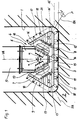
- Trench 1 shows a trench 1 in a soil 2, the trench 1 being essentially rectangular Cross section with a flat bottom 3.
- Trench 1 is a milling device 4, which on a movable arm 5 of a construction machine is attached and thus lowered into the ground or longitudinally movable in the working direction is.
- the milling device 4 comprises two arranged on a support member 6 Hydraulic motors 7, 8, on their motor shafts each a milling tool 9, 10 is attached.
- the milling tools 9 and 10 each have the shape of a truncated cone 19 and 20, which is centered on the shaft of the hydraulic motor 7 or 8, so that a longitudinal axis RA of Truncated cone 19, 20 the axis of rotation of the milling tool 9 or 10 forms.
- the longitudinal axes are RA to a vertical axis VA at an angle ⁇ 60 °, so that there is an angle ⁇ of the longitudinal axis RA compared to the bottom 3 of the trench 1 of 30 °.
- Angle ⁇ which the longitudinal axes RA enclose between them, is 120 °.
- the outer surface 11, 12 of the truncated cones 19, 20 are provided with a large number of milling cutters 18. Due to the longitudinal axis RA running obliquely to the floor 3 are the truncated cone shapes 19, 20 of the milling tools 9 and 10 aligned such that their lateral surfaces 11, 12th are aligned parallel to the floor 3.
- the lateral surfaces 11 and 12 of the milling tools 9 and 10 are located on their side adjacent to the floor 3 with their respective Base 13, 14 of the truncated cone shape 19, 20 while maintaining a working game 15 so together that there is a continuous working plane AE parallel to the floor 3 results.
- the truncated cones 19, 20 with their lateral surfaces 11, 12 can be close to each other at the base 13, 14 and the truncated cones are used to achieve a compact design 19, 20 at their base 13, 14 with a recess 16, 17 provided, in which the hydraulic motor 7, 8 at least is partially included, so that the lateral surface 11, 12th of the cone 19, 20 partially covers the hydraulic motor 7, 8.
- the truncated cones 19, 20 face in the respective Edge region of the trench 1 directed upper sides 13 'and 14' on.
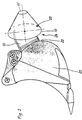
- FIG. 2 shows the side view of an excavator bucket 21, a milling device 24 on the rear 22 thereof is arranged.
- the milling device 24 comprises a supporting part 23 for the hydraulic motors not visible in FIG. 2 and the milling tools, of which only due to the side view a milling tool 25 is shown.
- the top 13 'of the truncated cone 19 based on the Base 13 of the milling tool 25, arranged off-center, see above that the working plane running parallel to the floor 3 AE according to FIG. 1 results.
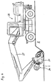
- FIG. 3 shows an excavator 26, on the arm 27 or Boom a combined device from excavator bucket 21 and milling device 24 is attached.
- Excavator bucket 21 When folded in Excavator bucket 21 is the milling tool 25 on the Soil 2 directed so that the trench 1 can be processed can.
- the milling tool 25 loosens the soil 2 in the width intended for the trench 1, a discharge of the soil from the trench is with the milling device 24th however not possible.
- the direction of work is with the arrow S denotes.
- the means is extracted the milling device 24 loosened soil through the bucket 21, which picks up the loosened soil, so that this by lifting the arm 27 and pivoting it sideways deposited outside the trench 1 or on a truck can be dropped for transport.
- FIG. 5 shows the top view of the milling device 4 with the two milling tools 9 and 10, which as in Fig. 1 shown by means of a support member 6 arranged Hydraulic motors 7, 8 are driven.
- the longitudinal direction the processing or digging is indicated with S, see above that it also becomes clear that Fig. 5 is a view is in the vertical direction.
- the Have axes of rotation RA of the two milling tools 9, 10 one to the longitudinal axis of the trench or the working direction S. Angle ⁇ 1 ⁇ 90 °. This will create a wedge shape in Working direction S is formed, which leads to the fact that Force vectors are directed towards the center of the support part 6 and thus self-centering or Effect directional stabilization.
- FIG. 6 is also a plan view of the Milling device 4 shows.
- the milling tools 9, 10 so strongly angled to Longitudinal direction S that the lateral surfaces 11, 12 of the frustoconical milling tools 9, 10 on the side in Working direction S include an angle ⁇ , which in Embodiment is approximately 160 °.
- This angle ⁇ should expediently be in the range between 150 ° and 160 ° lie.
Landscapes
- Engineering & Computer Science (AREA)
- Mechanical Engineering (AREA)
- Mining & Mineral Resources (AREA)
- Civil Engineering (AREA)
- General Engineering & Computer Science (AREA)
- Structural Engineering (AREA)
- Shovels (AREA)
- Finish Polishing, Edge Sharpening, And Grinding By Specific Grinding Devices (AREA)
- Earth Drilling (AREA)
Applications Claiming Priority (2)
| Application Number | Priority Date | Filing Date | Title |
|---|---|---|---|
| DE19754399 | 1997-12-09 | ||
| DE19754399A DE19754399C2 (de) | 1997-12-09 | 1997-12-09 | Vorrichtung zur Bearbeitung einer länglichen Vertiefung im Erdreich |
Publications (2)
| Publication Number | Publication Date |
|---|---|
| EP0922811A2 true EP0922811A2 (fr) | 1999-06-16 |
| EP0922811A3 EP0922811A3 (fr) | 2001-08-08 |
Family
ID=7851123
Family Applications (1)
| Application Number | Title | Priority Date | Filing Date |
|---|---|---|---|
| EP98123216A Withdrawn EP0922811A3 (fr) | 1997-12-09 | 1998-12-05 | Dispositif pour le traitment d'une cavité longitudinale dans le terrain |
Country Status (3)
| Country | Link |
|---|---|
| US (1) | US6085446A (fr) |
| EP (1) | EP0922811A3 (fr) |
| DE (1) | DE19754399C2 (fr) |
Cited By (2)
| Publication number | Priority date | Publication date | Assignee | Title |
|---|---|---|---|---|
| WO2000053855A1 (fr) * | 1999-01-29 | 2000-09-14 | Schenk Juergen | Dispositif permettant de defoncer des couches couvrant le sol |
| US11519153B2 (en) * | 2017-09-25 | 2022-12-06 | Soletanche Freyssinet | Boring machine for producing a non-rectilinear trench |
Families Citing this family (34)
| Publication number | Priority date | Publication date | Assignee | Title |
|---|---|---|---|---|
| US6751896B2 (en) | 2000-07-24 | 2004-06-22 | Lowell Underwood | Combination bucket/breaker apparatus for excavator boom stick |
| US7257910B2 (en) | 2000-07-24 | 2007-08-21 | Lowell Underwood | Impact resistant breaker deployment system for an excavating machine |
| US6430849B1 (en) * | 2000-07-24 | 2002-08-13 | Lowell A. Underwood | Combination bucket/breaker apparatus for excavator boom stick |
| US7117618B2 (en) * | 2000-07-24 | 2006-10-10 | Lowell A Underwood | Combination bucket/breaker apparatus for excavator boom stick |
| DE10041275B4 (de) * | 2000-08-23 | 2006-07-27 | Firma Klaus Ertmer Maschinenbautechnologie | Frässystem zum Anbau an hydraulische Trägergeräte |
| EP1362954A1 (fr) * | 2001-10-26 | 2003-11-19 | Fredy Stury AG | Tête de fraisage pour un engin de chantier |
| US20090107684A1 (en) | 2007-10-31 | 2009-04-30 | Cooke Jr Claude E | Applications of degradable polymers for delayed mechanical changes in wells |
| US20040231845A1 (en) | 2003-05-15 | 2004-11-25 | Cooke Claude E. | Applications of degradable polymers in wells |
| GB2435654B (en) * | 2006-03-01 | 2010-12-08 | Gareth John Thomas | Attachment for excavator |
| GB2435653C (en) * | 2006-03-01 | 2019-03-20 | John Thomas Gareth | Excavator |
| US7690138B2 (en) * | 2007-05-14 | 2010-04-06 | Hall David R | Rolling assembly mounted on a trencher |
| US7950170B2 (en) * | 2007-05-14 | 2011-05-31 | Hall David R | Skewed roller on an excavator |
| BE1018348A3 (nl) * | 2008-11-12 | 2010-09-07 | Dredging Int | Snijkop voor het baggeren van grond en werkwijze voor het baggeren met behulp van deze snijknop. |
| US8079413B2 (en) | 2008-12-23 | 2011-12-20 | W. Lynn Frazier | Bottom set downhole plug |
| US9217319B2 (en) | 2012-05-18 | 2015-12-22 | Frazier Technologies, L.L.C. | High-molecular-weight polyglycolides for hydrocarbon recovery |
| US9506309B2 (en) | 2008-12-23 | 2016-11-29 | Frazier Ball Invention, LLC | Downhole tools having non-toxic degradable elements |
| US8496052B2 (en) | 2008-12-23 | 2013-07-30 | Magnum Oil Tools International, Ltd. | Bottom set down hole tool |
| US8899317B2 (en) | 2008-12-23 | 2014-12-02 | W. Lynn Frazier | Decomposable pumpdown ball for downhole plugs |
| US9587475B2 (en) | 2008-12-23 | 2017-03-07 | Frazier Ball Invention, LLC | Downhole tools having non-toxic degradable elements and their methods of use |
| US9109428B2 (en) | 2009-04-21 | 2015-08-18 | W. Lynn Frazier | Configurable bridge plugs and methods for using same |
| US9181772B2 (en) | 2009-04-21 | 2015-11-10 | W. Lynn Frazier | Decomposable impediments for downhole plugs |
| US9062522B2 (en) | 2009-04-21 | 2015-06-23 | W. Lynn Frazier | Configurable inserts for downhole plugs |
| US9127527B2 (en) | 2009-04-21 | 2015-09-08 | W. Lynn Frazier | Decomposable impediments for downhole tools and methods for using same |
| US9163477B2 (en) | 2009-04-21 | 2015-10-20 | W. Lynn Frazier | Configurable downhole tools and methods for using same |
| US9562415B2 (en) | 2009-04-21 | 2017-02-07 | Magnum Oil Tools International, Ltd. | Configurable inserts for downhole plugs |
| ES2365956B1 (es) * | 2009-12-07 | 2012-09-07 | Rosendo Gómez Malbastre | Dispositivo transportador para cazos u otras herramientas, aplicable a una máquina mixta retroexcavadora o similar. |
| USD694280S1 (en) | 2011-07-29 | 2013-11-26 | W. Lynn Frazier | Configurable insert for a downhole plug |
| USD694281S1 (en) | 2011-07-29 | 2013-11-26 | W. Lynn Frazier | Lower set insert with a lower ball seat for a downhole plug |
| USD698370S1 (en) | 2011-07-29 | 2014-01-28 | W. Lynn Frazier | Lower set caged ball insert for a downhole plug |
| USD703713S1 (en) | 2011-07-29 | 2014-04-29 | W. Lynn Frazier | Configurable caged ball insert for a downhole tool |
| US9127442B1 (en) | 2014-04-22 | 2015-09-08 | Lowell Underwood | Bucket, breaker, and gripping apparatus for an excavator boom stick |
| DE102017112418B4 (de) * | 2017-06-06 | 2025-03-20 | Liebherr-Werk Nenzing Gmbh | Arbeitsmaschine mit einem Anbaugerät, insbesondere einer Schlitzwandfräse, sowie Anbaugerät, insbesondere Schlitzwandfräse |
| MX2022010802A (es) | 2021-10-15 | 2023-04-17 | Herzog Railroad Services Inc | Accesorio de zanjeo rotativo para un brazo manipulador de herramienta. |
| IT202100031592A1 (it) * | 2021-12-16 | 2023-06-16 | Mecc Breganzese S P A In Breve Mb S P A | Disgregatore rotante per escavatori e macchine operatrici in generale |
Family Cites Families (20)
| Publication number | Priority date | Publication date | Assignee | Title |
|---|---|---|---|---|
| AT24221B (de) * | 1905-02-27 | 1906-05-10 | Georg Schmidt | Mischmaschine für Beton, Mörtel u. dgl. |
| AT24211B (de) * | 1905-05-05 | 1906-05-10 | Clara Ehrenhoefer | Zigarettenhülse. |
| US2665655A (en) * | 1950-07-12 | 1954-01-12 | George R Brown | Machine for disintegrating and removing ice to form navigation channels |
| DE960592C (de) * | 1953-10-16 | 1957-03-21 | Baas Erwin | Antrieb fuer Grabenfraesen od. dgl. |
| DE960392C (de) * | 1954-02-27 | 1957-03-21 | Erwin Baas | Vorrichtung zur Herstellung neuer bzw. zum Reinigen bestehender Graeben |
| US3000620A (en) * | 1957-12-09 | 1961-09-19 | Joy Mfg Co | Mining and loading machine having angularly related rotary disintegrators |
| US3148917A (en) * | 1961-05-10 | 1964-09-15 | Western Gear Corp | Ice grader having vertical rotary cutters |
| US3341254A (en) * | 1965-05-28 | 1967-09-12 | Goodman Mfg Co | Method and machine for mining with relatively shiftable pairs of obtuse angled drum cutters |
| US3477762A (en) * | 1967-08-28 | 1969-11-11 | Eickhoff Geb | Mining machine and method |
| DE1756180A1 (de) * | 1968-04-17 | 1970-03-12 | Walter Schumann | Geraet zum Fraesen,Laden und Transportieren von Silofutter u.dgl. |
| US4100688A (en) * | 1976-08-19 | 1978-07-18 | Earth Pack, Inc. | Earth working apparatus |
| US4329087A (en) * | 1978-05-24 | 1982-05-11 | Unit Rig & Equipment Co. | Excavating and pipeline installation system |
| FR2542024B1 (fr) * | 1983-03-04 | 1985-07-19 | Cerimon | Machine a creuser et a curer les fosses |
| DE3603675A1 (de) * | 1986-02-06 | 1986-07-10 | Alfred Dr. 2095 Obermarschacht Hackmack | Als erdbewegungsgeraet ausgebildete kombination von einer fraese und einem behaelter |
| FR2601708B1 (fr) * | 1986-07-15 | 1989-10-27 | Soletanche | Engin pour creuser des tranchees dans le sol a l'aide de fraises |
| DE8704177U1 (de) * | 1987-03-20 | 1988-07-14 | Krumscheid Maschinen u. Werkzeugbau GmbH, 5466 Neustadt | Löffelbagger, insbesondere Tieflöffelbagger |
| US4793732A (en) * | 1988-01-21 | 1988-12-27 | Jordon Robert L | Pavement slot cutter |
| FI86320C (fi) * | 1990-05-18 | 1992-09-02 | Risto Nyberg | Anordning foer behandling av jordmaterial. |
| EP0496926A1 (fr) * | 1991-02-01 | 1992-08-05 | C.T.R. - Consulenti Tecnico-Commerciali Riuniti S.A.S. Di Miotti Anna E C. | Fraise pour creuser des tranchées |
| US5592761A (en) * | 1995-08-07 | 1997-01-14 | Ward; Arthur A. | Backhoe scarifying apparatus |
-
1997
- 1997-12-09 DE DE19754399A patent/DE19754399C2/de not_active Expired - Fee Related
-
1998
- 1998-12-05 EP EP98123216A patent/EP0922811A3/fr not_active Withdrawn
- 1998-12-09 US US09/208,810 patent/US6085446A/en not_active Expired - Fee Related
Cited By (3)
| Publication number | Priority date | Publication date | Assignee | Title |
|---|---|---|---|---|
| WO2000053855A1 (fr) * | 1999-01-29 | 2000-09-14 | Schenk Juergen | Dispositif permettant de defoncer des couches couvrant le sol |
| US6626499B1 (en) | 1999-01-29 | 2003-09-30 | Jurgen Schenk | Device for breaking up the outer layers of the ground |
| US11519153B2 (en) * | 2017-09-25 | 2022-12-06 | Soletanche Freyssinet | Boring machine for producing a non-rectilinear trench |
Also Published As
| Publication number | Publication date |
|---|---|
| US6085446A (en) | 2000-07-11 |
| DE19754399A1 (de) | 1999-06-17 |
| EP0922811A3 (fr) | 2001-08-08 |
| DE19754399C2 (de) | 2002-04-25 |
Similar Documents
| Publication | Publication Date | Title |
|---|---|---|
| DE19754399C2 (de) | Vorrichtung zur Bearbeitung einer länglichen Vertiefung im Erdreich | |
| DE102008041982B4 (de) | Anbaufrässystem mit Schneidköpfen und Fräskette | |
| EP0499682B1 (fr) | Godet pour engin de terrassement | |
| DE2140111A1 (de) | Zweiteilige Schaufelkante für Flachbagger od. dgl | |
| DE2947466A1 (de) | Grabenbagger | |
| DE2629284C3 (de) | Fräsmaschine zur Bankett-, Graben- und Böschungsreinigung | |
| DE3920011C2 (fr) | ||
| EP3670759B1 (fr) | Dispositif et procédé de pose de câbles et / ou de conduites dans le sol | |
| DE3234019A1 (de) | Hydraulikbaggerausruestung | |
| DE4213523B4 (de) | Mobiles Fräsladegerät, insbesondere Bodenfräsgerät | |
| DE1634691B1 (de) | Arbeitsgerät für Baumaschinen, insbesondere Bagger mit mehreren meisselartigen Zähnen | |
| DE8812484U1 (de) | Vorrichtung zur Bearbeitung von Waldböden | |
| DE19512714C2 (de) | Böschungsprofiliergerät | |
| DE69505090T2 (de) | Werkzeuganbauvorrichtung für ein Maschinen-Schneidrad | |
| DE2805593C2 (de) | Vorrichtung mit einer motorisch angetriebenen, um eine Achse rotierenden und messerartige Grabwerkzeuge aufweisenden Fräse | |
| DE4016759C2 (de) | Hydraulikhammer-Löffel-Kombination | |
| DE10041275B4 (de) | Frässystem zum Anbau an hydraulische Trägergeräte | |
| DE2429659A1 (de) | Loeffelbagger, insbesondere tiefloeffelbagger | |
| DE2143018A1 (de) | Grabenbagger | |
| DE4321556C2 (de) | Walze mit Arbeitsorganen zur Tiefenmelioration von Böden | |
| DE2625680A1 (de) | Fahrbares arbeitsgeraet, insbesondere hydraulikbagger | |
| DE1634691C (de) | Arbeitsgerät fur Baumaschinen, ins besondere Bagger, mit mehreren meißelarti gen Zahnen | |
| DE29705899U1 (de) | Schachtbagger | |
| DE3709186A1 (de) | Loeffelbagger, insbesondere tiefloeffelbagger | |
| DE1966966A1 (de) | Vorrichtung zum abtragen verschlissener strassendecken |
Legal Events
| Date | Code | Title | Description |
|---|---|---|---|
| PUAI | Public reference made under article 153(3) epc to a published international application that has entered the european phase |
Free format text: ORIGINAL CODE: 0009012 |
|
| AK | Designated contracting states |
Kind code of ref document: A2 Designated state(s): AT BE CH DE DK ES FI FR GB IE IT LI LU NL PT SE |
|
| AX | Request for extension of the european patent |
Free format text: AL;LT;LV;MK;RO;SI |
|
| PUAL | Search report despatched |
Free format text: ORIGINAL CODE: 0009013 |
|
| AK | Designated contracting states |
Kind code of ref document: A3 Designated state(s): AT BE CH CY DE DK ES FI FR GB GR IE IT LI LU MC NL PT SE |
|
| AX | Request for extension of the european patent |
Free format text: AL;LT;LV;MK;RO;SI |
|
| 17P | Request for examination filed |
Effective date: 20020131 |
|
| AKX | Designation fees paid |
Free format text: AT BE CH DE DK ES FI FR GB IE IT LI LU NL PT SE |
|
| GRAP | Despatch of communication of intention to grant a patent |
Free format text: ORIGINAL CODE: EPIDOSNIGR1 |
|
| GRAS | Grant fee paid |
Free format text: ORIGINAL CODE: EPIDOSNIGR3 |
|
| STAA | Information on the status of an ep patent application or granted ep patent |
Free format text: STATUS: THE APPLICATION IS DEEMED TO BE WITHDRAWN |
|
| 18D | Application deemed to be withdrawn |
Effective date: 20060701 |