EP0922812A2 - Conveying system for a two-phase flow - Google Patents
Conveying system for a two-phase flow Download PDFInfo
- Publication number
- EP0922812A2 EP0922812A2 EP98204191A EP98204191A EP0922812A2 EP 0922812 A2 EP0922812 A2 EP 0922812A2 EP 98204191 A EP98204191 A EP 98204191A EP 98204191 A EP98204191 A EP 98204191A EP 0922812 A2 EP0922812 A2 EP 0922812A2
- Authority
- EP
- European Patent Office
- Prior art keywords
- conveyor
- guide means
- conveyor system
- pipeline
- flow
- Prior art date
- Legal status (The legal status is an assumption and is not a legal conclusion. Google has not performed a legal analysis and makes no representation as to the accuracy of the status listed.)
- Withdrawn
Links
- 230000005514 two-phase flow Effects 0.000 title claims abstract description 10
- 239000004576 sand Substances 0.000 claims abstract description 5
- XLYOFNOQVPJJNP-UHFFFAOYSA-N water Substances O XLYOFNOQVPJJNP-UHFFFAOYSA-N 0.000 claims abstract description 5
- 238000011144 upstream manufacturing Methods 0.000 claims abstract description 4
- 239000007787 solid Substances 0.000 claims description 8
- 239000000470 constituent Substances 0.000 claims description 2
- 230000002787 reinforcement Effects 0.000 claims 1
- 239000007788 liquid Substances 0.000 description 21
- 239000002245 particle Substances 0.000 description 19
- 230000000694 effects Effects 0.000 description 8
- 239000000463 material Substances 0.000 description 8
- 239000000203 mixture Substances 0.000 description 7
- 238000013459 approach Methods 0.000 description 6
- 230000008901 benefit Effects 0.000 description 3
- 239000008240 homogeneous mixture Substances 0.000 description 3
- 239000000725 suspension Substances 0.000 description 3
- 230000009471 action Effects 0.000 description 2
- -1 gravel Substances 0.000 description 2
- 229910052500 inorganic mineral Inorganic materials 0.000 description 2
- 230000003993 interaction Effects 0.000 description 2
- 239000011707 mineral Substances 0.000 description 2
- 229920000642 polymer Polymers 0.000 description 2
- 230000015572 biosynthetic process Effects 0.000 description 1
- 230000008859 change Effects 0.000 description 1
- 239000003245 coal Substances 0.000 description 1
- 239000008187 granular material Substances 0.000 description 1
- 230000006872 improvement Effects 0.000 description 1
- 238000009434 installation Methods 0.000 description 1
- 238000005065 mining Methods 0.000 description 1
- 239000011343 solid material Substances 0.000 description 1
- 230000007704 transition Effects 0.000 description 1
Images


Classifications
-
- E—FIXED CONSTRUCTIONS
- E02—HYDRAULIC ENGINEERING; FOUNDATIONS; SOIL SHIFTING
- E02F—DREDGING; SOIL-SHIFTING
- E02F7/00—Equipment for conveying or separating excavated material
- E02F7/10—Pipelines for conveying excavated materials
-
- E—FIXED CONSTRUCTIONS
- E02—HYDRAULIC ENGINEERING; FOUNDATIONS; SOIL SHIFTING
- E02F—DREDGING; SOIL-SHIFTING
- E02F3/00—Dredgers; Soil-shifting machines
- E02F3/04—Dredgers; Soil-shifting machines mechanically-driven
- E02F3/88—Dredgers; Soil-shifting machines mechanically-driven with arrangements acting by a sucking or forcing effect, e.g. suction dredgers
- E02F3/90—Component parts, e.g. arrangement or adaptation of pumps
- E02F3/902—Component parts, e.g. arrangement or adaptation of pumps for modifying the concentration of the dredged material, e.g. relief valves preventing the clogging of the suction pipe
Definitions
- the invention relates to the conveying of a two-phase flow in a conveyor pipeline.
- a two-phase flow of this nature occurs, for example, in the hydraulic conveying of dredged material.
- the flow is formed by water containing a granular material, such as sand, gravel, stones and the like.
- a two-phase flow relates to the pneumatic conveying of solids.
- the bed also moves forwards under the influence of the pressure difference across the pipeline, generated by a pump, for example.
- This pressure difference together with the interaction between flow and bed, causes the bed to move.
- the object of the invention is to provide a conveyor system for conveying a mixture of liquid and solid particles which are to be conveyed which provides improved efficiency.
- a conveyor system for a two-phase flow such as water containing sand, gravel and the like, comprising at least one conveyor pipeline with means for generating a flow, in which system the internal surface of the conveyor line bears guide means for influencing the flow.
- the guide means on the internal surface of the conveyor line offer the option of locally transferring momentum from the liquid flow to the bed.
- the ideal situation would then again result in a homogeneous mixture with a specific average speed.
- the average speed of a mixture of this nature will be higher than that of the original bed and lower than that of the original flow.
- the guide means in a conveyor system in which a pump is accommodated in the conveyor pipeline, there is provision for the guide means to be situated immediately upstream of the inlet of the pump.
- the guide means may be designed to impart a preliminary rotation to the flow.
- the guide means are preferably situated opposite the advancing bed of solid particles, which usually means in the highest part of the conveyor pipeline. However, this does not always have to be so. In non-horizontal parts of the conveyor pipeline, the guide means may also be situated at a different location from the highest part. Moreover, the bed of mineral constituents may be situated at numerous other positions if there are bends and branches in the pipeline.
- the material in the bed then does not come into contact with the guide means, but rather only the liquid or suspension flow does so.
- This liquid flow is therefore given a momentum in the direction of rotation by the guide means.
- the liquid flow then transmits this rotational momentum to the bed, which as a result acquires a direction of movement and speed which are such that the approach to the vanes of a rotary pump can take place in a more uniform manner and at a more suitable inflow angle, with less intensive impacts.
- a further advantage is that a suitably configured guidance also reduces the susceptibility of the pump to cavitation, despite the flow resistance caused by the guidance.
- the guide means may be plate-like and extend essentially radially from the internal surface.
- the guide means may extend radially to a distance from the centre axis of the conveyor pipeline. This distance depends on the (average) level of bed conveyance per unit time and the extent to which the momentum is to be transferred in order to achieve the desired effect, while it is desirable to minimize the surface area of the guide in order to keep the inevitable associated pressure drop as low as possible.
- the guide means are preferably accommodated in a pipeline section which has an orientation which can be adjusted in the circumferential direction.
- the rotational position of the guide means may be adjusted in such a manner, for example with respect to a pump, that the maximum effect is ensured.
- the radially inner edge of the plate-like guide means may be provided with an end plate which extends in the longitudinal direction.
- the end plate may be curved in a corresponding manner to the curvature of the conveyor pipeline and may be designed as a concentric pipe piece.
- the conveyor system according to the invention which is illustrated in Figure 1 comprises a conveyor pipeline which is denoted overall by 1, a rotary pump 2, more particularly a centrifugal pump, and a discharge line 3.
- the conveyor pipeline 1 is connected to the spiral casing 5 of the centrifugal pump 2 via a flange 4.
- a guide means which is denoted overall by 7, is attached to the internal wall 6 thereof.
- this guide means contains a guide plate 8 which has a straight section 9 which runs in the axial and radial direction of the conveyor line 1 and an adjoining helical plate section 8.
- the flow through the conveyor system as indicated by the arrows in Figure 1, firstly meets the straight plate section 9, and then a rotary movement is imparted to the flow by the helical plate section 8.
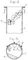
- a curved plate piece 11 which has bevelled front and rear edges 12 and 13, respectively, is welded to the radially inner side of the guide member 8, as indicated in Figures 2 and 3.
- the conveyor system in accordance with Figure 1 is used for a two-phase flow, i.e. a liquid containing solid particles.
- a two-phase flow of this nature a relatively slow-moving bed 14 of larger solid pieces forms on the bottom of the conveyor pipeline 1, and liquid containing suspended smaller solid particles flows above this bed.
- this liquid is given a velocity component in the rotational direction about the centre axis of the conveyor pipeline 1.
- the liquid moving in this direction collides with the bed 14, resulting in a transfer of momentum.
- the bed 14 acquires an additional velocity component in the direction of rotation and also moves/rotates in that direction, as illustrated by means of the bed section 15 in Figure 3.
- the helical section 9 has an end edge 21 which is preferably parallel to the displaced bed 15.
- a further effect of the transfer of momentum between liquid and bed material is that a more uniform or more homogeneous mixture is obtained.
- Paddles of this nature also impart a velocity component in the direction of rotation to the liquid flow, which velocity component again leads to a transfer of momentum to the bed material 14.
- At least one of the paddles 16 may be designed with a fixed blade part 22 and an adjustable blade part 23, in order to be able to influence the size and direction of the deflection angle.
- guide means according to the invention have been described above in combination with a rotary pump, other applications are also conceivable. Another application of this nature relates to the positioning of guide means upstream of and in the vicinity of a pipe bend in order to reduce the wear in that area.
- Another application is possible by arranging the guide means according to the invention at more or less regular intervals in straight conveyor pipelines, in order to allow the two-phase conveying to proceed more efficiently, i.e. the conveying results in a lower average pipeline resistance and the wear is distributed more uniformly over the pipeline wall.
Landscapes
- Engineering & Computer Science (AREA)
- Mining & Mineral Resources (AREA)
- Civil Engineering (AREA)
- General Engineering & Computer Science (AREA)
- Structural Engineering (AREA)
- Mechanical Engineering (AREA)
- Structures Of Non-Positive Displacement Pumps (AREA)
- Excavating Of Shafts Or Tunnels (AREA)
- Air Transport Of Granular Materials (AREA)
Abstract
Description
Claims (15)
- Conveyor system for a two-phase flow, such as water containing sand, gravel and the like, comprising at least one conveyor pipeline (1) with means (2) for generating a flow, characterized in that the internal surface (6) of the conveyor line (1) bears guide means (7, 16) for influencing the flow.
- Conveyor system according to Claim 1, in which a pump (2) is accommodated in the conveyor pipeline (1) and the guide means (7, 16) are situated immediately upstream of the inlet of the pump.
- Conveyor system according to Claim 2, in which the pump (2) is a rotary pump and the guide means (7, 16) are designed to impart a preliminary rotation to the flow.
- Conveyor system according to one of Claims 1-3, in which the guide means (7, 16) are situated in that part of the conveyor pipeline (1) which lies opposite a bed of solid constituents which has been formed in the conveyor pipeline.
- Conveyor system according to Claim 3 or 4, in which the guide means extend at least partially at an angle with respect to the conveyor pipeline (1).
- Conveyor system according to Claim 5, in which the guide means (7) are plate-like and extend essentially radially from the internal surface (1).
- Conveyor system according to Claim 6, in which the guide means (7) extend radially to a distance from the centre axis of the conveyor pipeline (1).
- Conveyor system according to Claim 6 or 7, in which the guide means (7) comprise an essentially helical plate (10).
- Conveyor system according to Claim 8, in which the helical plate has a pitch angle which increases in the direction of flow.
- Conveyor system according to Claim 8 or 9, in which the guide means (7) have a plate section (9) which is straight and axial in the direction of conveyance and adjoins a helical plate section (18).
- Conveyor system according to one of the preceding claims, in which the guide means (7) are accommodated in a pipeline section which has an orientation which can be adjusted in the circumferential direction.
- Conveyor system according to one of Claims 6-10, in which a reinforcement edge or end plate (11) which extends in the longitudinal direction is provided on the radially inner edge of the plate-like guide means (8).
- Conveyor system according to Claim 12, in which the end plate (11) is curved in a corresponding manner to the curvature of the conveyor pipeline (1).
- Conveyor system according to Claim 12 or 13, in which the end plate is a pipe piece (11) which is concentric with respect to the conveyor line (1).
- Conveyor system according to one of the preceding claims, in which a plurality of guide means are provided, which are situated one behind the other, at regular intervals, in an essentially straight conveyor pipeline.
Applications Claiming Priority (2)
| Application Number | Priority Date | Filing Date | Title |
|---|---|---|---|
| NL1007763 | 1997-12-10 | ||
| NL1007763A NL1007763C2 (en) | 1997-12-10 | 1997-12-10 | Transport system for a two-phase flow. |
Publications (2)
| Publication Number | Publication Date |
|---|---|
| EP0922812A2 true EP0922812A2 (en) | 1999-06-16 |
| EP0922812A3 EP0922812A3 (en) | 2000-02-02 |
Family
ID=19766166
Family Applications (1)
| Application Number | Title | Priority Date | Filing Date |
|---|---|---|---|
| EP98204191A Withdrawn EP0922812A3 (en) | 1997-12-10 | 1998-12-09 | Conveying system for a two-phase flow |
Country Status (2)
| Country | Link |
|---|---|
| EP (1) | EP0922812A3 (en) |
| NL (1) | NL1007763C2 (en) |
Cited By (4)
| Publication number | Priority date | Publication date | Assignee | Title |
|---|---|---|---|---|
| WO2003002878A3 (en) * | 2001-06-28 | 2003-02-27 | Martin John Gardner Doig | Apparatus for fluid transportation |
| US7644733B2 (en) | 2002-04-25 | 2010-01-12 | The University Of Nottingham | Duct with spiral groove |
| CN103410184A (en) * | 2013-08-16 | 2013-11-27 | 招商局重工(深圳)有限公司 | Broadside suction opening of dredger and dredger |
| WO2017021708A3 (en) * | 2015-07-31 | 2017-03-16 | Rotech Group Limited | Separator apparatus |
Family Cites Families (9)
| Publication number | Priority date | Publication date | Assignee | Title |
|---|---|---|---|---|
| NL81617C (en) * | 1900-01-01 | |||
| DE138186C (en) * | ||||
| US1451272A (en) * | 1921-10-01 | 1923-04-10 | Arthur W Robinson | Delivery pipe for hydraulic dredging machines |
| US1662178A (en) * | 1927-01-19 | 1928-03-13 | Nathaniel A Yuille | Dredger pipe line |
| FR77711E (en) * | 1960-05-14 | 1962-04-13 | Dredging facility | |
| BE758739A (en) * | 1969-11-13 | 1971-04-16 | Fuji Photo Film Co Ltd | METHOD AND APPARATUS FOR TRANSPORTING A FLUID |
| JPS5236219A (en) * | 1975-09-13 | 1977-03-19 | Teruo Kashiwara | Exhaust equipment for internal combustion engine |
| JPS6250530A (en) * | 1985-08-28 | 1987-03-05 | Toyo Kensetsu Kk | Transportation of slurry by pump-type dredger |
| DE3901301A1 (en) * | 1989-01-18 | 1990-07-26 | Klein Alb Gmbh Co Kg | Pipeline for pneumatically conveying bulk material |
-
1997
- 1997-12-10 NL NL1007763A patent/NL1007763C2/en not_active IP Right Cessation
-
1998
- 1998-12-09 EP EP98204191A patent/EP0922812A3/en not_active Withdrawn
Cited By (6)
| Publication number | Priority date | Publication date | Assignee | Title |
|---|---|---|---|---|
| WO2003002878A3 (en) * | 2001-06-28 | 2003-02-27 | Martin John Gardner Doig | Apparatus for fluid transportation |
| GB2395026A (en) * | 2001-06-28 | 2004-05-12 | Martin John Gardner Doig | Apparatus for fluid transportation |
| US7644733B2 (en) | 2002-04-25 | 2010-01-12 | The University Of Nottingham | Duct with spiral groove |
| CN103410184A (en) * | 2013-08-16 | 2013-11-27 | 招商局重工(深圳)有限公司 | Broadside suction opening of dredger and dredger |
| CN103410184B (en) * | 2013-08-16 | 2015-10-14 | 招商局重工(深圳)有限公司 | A kind of topside suction inlet of dredge boat and a kind of dredge boat |
| WO2017021708A3 (en) * | 2015-07-31 | 2017-03-16 | Rotech Group Limited | Separator apparatus |
Also Published As
| Publication number | Publication date |
|---|---|
| NL1007763C2 (en) | 1999-06-23 |
| EP0922812A3 (en) | 2000-02-02 |
Similar Documents
| Publication | Publication Date | Title |
|---|---|---|
| AU2021204411B2 (en) | Material flow amplifier | |
| US20110005291A1 (en) | Method and apparatus for forming undulating conduit | |
| US4865353A (en) | Abrasion resistant ceramic elbow | |
| CA2549895C (en) | Hydrodynamic static mixing apparatus and method for use thereof in transporting, conditioning and separating oil sands and the like | |
| US11002301B1 (en) | Material flow modifier and apparatus comprising same | |
| NL1007763C2 (en) | Transport system for a two-phase flow. | |
| EP0094811A2 (en) | Apparatus and method for conveying different types of material | |
| EP1365978B1 (en) | Screw conveyor comprising two concentric shaftless screws | |
| WO1998015769A1 (en) | Low erosive wear elbow joint design | |
| KR100523857B1 (en) | Elbow Pipe for Pneumatic Conveying System | |
| AU2022271260B2 (en) | Dredge system | |
| CAPLAN | Fluid Flow, Slurry Systems and Pipelines | |
| CN216880858U (en) | Prevent blockking up conveying pipe | |
| CN223242375U (en) | A slurry conveying pipeline | |
| JP7379873B2 (en) | gas conveyance device | |
| KR19990064820A (en) | stiffening method system for abrasion resistance fittings | |
| JPS62220214A (en) | Thickness deviated steel tube | |
| JP2003301990A (en) | Fluid transport pipe | |
| CAPLAN | Slurry Systems and Pipelines | |
| JPS62220215A (en) | Slurry transportation steel tube | |
| JPS5961749A (en) | Apparatus for detecting precipitation layer in slurry fluid flowing and distributing pipe | |
| JPS5943999A (en) | Concrete pump and its use | |
| JPH02204218A (en) | Slurry producing/conveying system | |
| WO2000065163A1 (en) | Method and apparatus for removing particulate solids from a fluid stream |
Legal Events
| Date | Code | Title | Description |
|---|---|---|---|
| PUAI | Public reference made under article 153(3) epc to a published international application that has entered the european phase |
Free format text: ORIGINAL CODE: 0009012 |
|
| AK | Designated contracting states |
Kind code of ref document: A2 Designated state(s): BE DE GB NL |
|
| AX | Request for extension of the european patent |
Free format text: AL;LT;LV;MK;RO;SI |
|
| PUAL | Search report despatched |
Free format text: ORIGINAL CODE: 0009013 |
|
| AK | Designated contracting states |
Kind code of ref document: A3 Designated state(s): AT BE CH CY DE DK ES FI FR GB GR IE IT LI LU MC NL PT SE |
|
| AX | Request for extension of the european patent |
Free format text: AL;LT;LV;MK;RO;SI |
|
| 17P | Request for examination filed |
Effective date: 20000731 |
|
| AKX | Designation fees paid |
Free format text: BE DE GB NL |
|
| 17Q | First examination report despatched |
Effective date: 20050329 |
|
| STAA | Information on the status of an ep patent application or granted ep patent |
Free format text: STATUS: THE APPLICATION IS DEEMED TO BE WITHDRAWN |
|
| 18D | Application deemed to be withdrawn |
Effective date: 20050701 |