EP0922822A1 - Vorrichtung zur Freigabe eines Schlüssels - Google Patents
Vorrichtung zur Freigabe eines Schlüssels Download PDFInfo
- Publication number
- EP0922822A1 EP0922822A1 EP97115095A EP97115095A EP0922822A1 EP 0922822 A1 EP0922822 A1 EP 0922822A1 EP 97115095 A EP97115095 A EP 97115095A EP 97115095 A EP97115095 A EP 97115095A EP 0922822 A1 EP0922822 A1 EP 0922822A1
- Authority
- EP
- European Patent Office
- Prior art keywords
- locking
- lock
- key
- release medium
- holding element
- Prior art date
- Legal status (The legal status is an assumption and is not a legal conclusion. Google has not performed a legal analysis and makes no representation as to the accuracy of the status listed.)
- Granted
Links
- 238000003780 insertion Methods 0.000 claims description 11
- 230000037431 insertion Effects 0.000 claims description 11
- 230000000903 blocking effect Effects 0.000 claims description 8
- 230000006835 compression Effects 0.000 claims description 2
- 238000007906 compression Methods 0.000 claims description 2
- 230000002093 peripheral effect Effects 0.000 claims 1
- 238000007747 plating Methods 0.000 abstract 1
- 230000009182 swimming Effects 0.000 description 3
- 238000003287 bathing Methods 0.000 description 1
- 235000013361 beverage Nutrition 0.000 description 1
- 230000005540 biological transmission Effects 0.000 description 1
- 230000015572 biosynthetic process Effects 0.000 description 1
- 238000006073 displacement reaction Methods 0.000 description 1
- 210000003746 feather Anatomy 0.000 description 1
- 230000003993 interaction Effects 0.000 description 1
- 238000002372 labelling Methods 0.000 description 1
- 238000000034 method Methods 0.000 description 1
Images


Classifications
-
- G—PHYSICS
- G07—CHECKING-DEVICES
- G07F—COIN-FREED OR LIKE APPARATUS
- G07F7/00—Mechanisms actuated by objects other than coins to free or to actuate vending, hiring, coin or paper currency dispensing or refunding apparatus
- G07F7/06—Mechanisms actuated by objects other than coins to free or to actuate vending, hiring, coin or paper currency dispensing or refunding apparatus by returnable containers, i.e. reverse vending systems in which a user is rewarded for returning a container that serves as a token of value, e.g. bottles
- G07F7/0618—Mechanisms actuated by objects other than coins to free or to actuate vending, hiring, coin or paper currency dispensing or refunding apparatus by returnable containers, i.e. reverse vending systems in which a user is rewarded for returning a container that serves as a token of value, e.g. bottles by carts
- G07F7/0654—Mechanisms actuated by objects other than coins to free or to actuate vending, hiring, coin or paper currency dispensing or refunding apparatus by returnable containers, i.e. reverse vending systems in which a user is rewarded for returning a container that serves as a token of value, e.g. bottles by carts in which the lock functions according to a "pinching of the token" principle, i.e. the token is held between two members
-
- G—PHYSICS
- G07—CHECKING-DEVICES
- G07F—COIN-FREED OR LIKE APPARATUS
- G07F17/00—Coin-freed apparatus for hiring articles; Coin-freed facilities or services
- G07F17/10—Coin-freed apparatus for hiring articles; Coin-freed facilities or services for means for safe-keeping of property, left temporarily, e.g. by fastening the property
- G07F17/12—Coin-freed apparatus for hiring articles; Coin-freed facilities or services for means for safe-keeping of property, left temporarily, e.g. by fastening the property comprising lockable containers, e.g. for accepting clothes to be cleaned
-
- E—FIXED CONSTRUCTIONS
- E05—LOCKS; KEYS; WINDOW OR DOOR FITTINGS; SAFES
- E05B—LOCKS; ACCESSORIES THEREFOR; HANDCUFFS
- E05B11/00—Devices preventing keys from being removed from the lock ; Devices preventing falling or pushing out of keys
- E05B11/02—Devices preventing keys from being removed from the lock ; Devices preventing falling or pushing out of keys before the wing is locked
-
- E—FIXED CONSTRUCTIONS
- E05—LOCKS; KEYS; WINDOW OR DOOR FITTINGS; SAFES
- E05B—LOCKS; ACCESSORIES THEREFOR; HANDCUFFS
- E05B19/00—Keys; Accessories therefor
Definitions
- the invention relates to a device for releasing a key, in particular a locker key that is in the open position of the lock is held by a lock in the castle and only after unlocking the Lock in the closed position of the lock can be pulled out of the lock, being the lock is unlocked using a release medium.
- Such devices are, for example, locker locks on sports or Recreational facilities known. These known release devices work with a card or coin as release medium, which is in the castle is introduced. Once the release medium is in the locking mechanism is introduced, the rotary movement to lock the locker Approved. The release medium then remains for the entire time, in which the locker is locked, inside the locker and can only after opening the locker again.
- the user of the facility is next to the pure use of, for example, the swimming pool is also offered use other services such as sauna and solarium.
- the swimming pool With swimming pools in particular, it has been found that the users the swimming pool hardly needs these additional services as they do not have any cash or anything else after moving Carry with you to the additional services as well To be able to use food and drink offers.
- From DE-U-9209666 is a key for opening mechanical or Electromagnetic locks known, in the handle of which by means of a external interrogation unit identifiable without contact, for example, a transponder is arranged.
- Can in the transponder For example, a certain monetary value may be saved when in use various services or the purchase of food and drinks is automatically debited. It is also possible to use the To store services and the like on the transponder and when leaving the sports or leisure facility on the transponder to pay the saved amount.
- a disadvantage of this known system on the one hand that no free choice of locker can take place because of the issue of the key to the user of the locker to be used and on the other hand that the issue of using a fastening strap provided locker key can not be done fully automatically.
- the invention has for its object to provide a device of the type mentioned, which on the one hand allows a fully automatic output of the release medium with simultaneous free locker selection, and on the other hand allows the user to continue to use the release medium for the use of additional services and the like.
- the lock consists of a locking element forming the handle of the key and a holding element fastened to the lock and / or the door leaf and interacting with the locking element, the release medium being insertable into the locking element.
- This inventive design of a device for release of a key it is possible for the user to use one with a Lock provided device according to the invention after purchase any lock or locker of the release medium can choose, because all release media are identical and thus used to release any key still available can be. Because the user when entering the sports or leisure facility only the release medium, but not a corresponding one, with a Holding device provided key, it is possible to Output of the release media fully automatically, for example on one To run ticket machines.
- the release media are as a transponder, i.e. as an electronically readable and writable memory for contactless data transmission, so that the user with the once acquired release medium, which after removal of the Key remains in the locking element designed as a key handle, also the other services without using cash or can use other means of payment.
- a transponder i.e. as an electronically readable and writable memory for contactless data transmission
- the user with the once acquired release medium, which after removal of the Key remains in the locking element designed as a key handle, also the other services without using cash or can use other means of payment.
- transponders with a predetermined amount of money, for example or to save the services used in the transponder, which the user then exits when leaving the sports or leisure facility has to pay or which are debited from his account.
- the holding element is as formed around the locking element rosette.
- This configuration of the Holding element has the advantage that the locking element and thus the Key completely secured against manipulation by the holding element are.
- the blocking element a housing in which at least one about a fulcrum pivotable locking arm provided with at least one locking lug is arranged that when not or not completely in the locking element introduced release medium, the at least one latch of the at least a locking arm through an opening in the housing of the locking element engages in at least one recess in the holding element.
- the housing of the Locking element two each pivotable about a pivot point a locking nose provided locking arms arranged.
- a particularly secure hold of the locking element in the holding element is one practical embodiment of the invention achieved in that each locking arm than in each case pivotable about an approximately centrally arranged pivot point is formed two-leg rocker arm, the at least one Locking lug per locking arm pointing outwards at a free end of one leg each locking arm is arranged, but preferably on both free Leg ends of each locking arm each have an outwardly facing locking lug is arranged.
- the locking arms as about an approximately center arranged pivot pivot rocker arm with free on both Leg ends arranged locking lugs will double the Locking element in the holding element allows, which to which the Insertion opening for leg ends removed from the release medium arranged locking lugs a rotation of the key or Prevent the blocking element when the release medium is not used and the on the leg end near the insertion opening for the release medium arranged locking lugs a rotation of the locking element during the Prevent insertion of the release medium into the locking element, as well as at the release medium used pulling out the release medium prevent.
- the spring element that pushes the two spring arms apart preferably arranged above the fulcrums of the two locking arms by spreading the locking arms in the pulled state of the Key the setting of the release medium in the locking element support.
- the recesses in the holding element for receiving the locking lugs as arranged in the axial direction of the holding element Longitudinal grooves formed. By engaging the locking lugs in this Longitudinal grooves are not possible to use the key without a release medium Twist locking element within the lock.
- the longitudinal grooves are closed at the front by a circumferential edge to prevent manipulation to prevent the locking lugs.
- the invention proposes that on the Housing base of the locking element, a guide is formed on the a locking bolt slidably arranged in the longitudinal direction of the locking element is.
- the key is at the insertion opening for the Release medium opposite end of the housing of the locking element attached to a key holder.
- the locking bolt is in the plan view is substantially T-shaped, towards the Key holder spring loaded so arranged on the guide that the vertical leg of the locking bolt in one in the key holder trained recess is insertable. Furthermore, the invention proposed that at least one on the free end face of the castle Guide pin is arranged so that this in the key holder trained recess engages.
- the invention proposes that the horizontal Leg of the locking bolt with the key removed between the Locking arms is arranged that this a compression of the locking arms prevented.
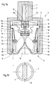
- Figures 1a, 2a and 3a each show a longitudinal section through a device for releasing a key 1 in the open position a lock 2 is held in the lock 2 by means of a lock 3.
- a lock 2 is held in the lock 2 by means of a lock 3.
- Such devices are used for example in locker locks Bathing establishments and similar sports facilities used.
- release medium 4 returned to the user and the key 1 again held immovably in lock 2 by means of the lock 3.
- the one shown Embodiment the lock 3 from a fixed at the castle 2 or not Door leaf shown fastened holding element 5 and one in the Holding element 5 arranged, forming the handle of the key 1 Locking element 6.
- a great advantage of this device compared to the stand The technique is that the locking element 6 has a receiving space 6a for the release medium 4. Because of this configuration remains the release medium 4 with the locker locked and the key removed 1 by the fixed connection with the locking element 6 at the user, so that the latter the release medium 4 for the use of further services and the like can be used in the sports and leisure facility, if that Release medium 4, for example, as a transponder, that is, electronically readable and writable memory is formed.
- the locking element 6 consists of a housing 7 and two on the Housing base 7a arranged locking arms 8, which on the Housing base 7a arranged pivot points 7b are pivotable. How 1a, 2a and 3a can be seen, the receiving space 6a for the release medium 4 between the housing base 7a and the the housing base 7a arranged locking arms 8 formed.
- the Latching arms 8 are mirror-symmetrical as two-leg rocker arms the pivot point 7b in the longitudinal extension of the locking arms 8 seen is arranged approximately in the middle.
- At the two free ends of the legs of each locking arm 8 is an outwardly facing locking lug 8a and 8b integrally formed by the corresponding when pivoting the locking arms 8 Openings 7c in the housing 7 can emerge from the housing 7.
- the key 1 is at the end opposite an insertion opening 7d the housing 7 attached to a key holder 10.
- Arranged locking bolt 11 has the key holder 10 from Key 1 facing recess 10a.
- a receiving pocket 11a is formed in which a spring 12 is arranged is through which the locking bolt 11 in the direction of the recess 10a Key holder 10 is spring-loaded.
- the locking bolt 11 is at illustrated embodiment is substantially T-shaped, so arranged on the guide 7e that the vertical leg 11b of the Locking bolt 11 can be inserted into the recess 10a of the key receptacle 10 is.
- a through opening 7f is formed in the housing 7 serves to pull a tether.
- Holding element 5 formed as longitudinal grooves 5b recesses, into which the locking lugs 8a and 8b of the locking arms 8 of the locking element 6 engage can.
- Those formed in the inner lateral surface 5a of the holding element 5 Longitudinal grooves 5b are to the free end face 5c of the holding element 5 by a closed inwardly projecting edge 5d to prevent manipulation of the To prevent locking lugs 8a and 8b.
- Fig. 1a shows the device in the open position, in which the key 1 over the lock 3 consisting of the holding element 5 and the locking element 6 cannot be rotated and is not pulled out in lock 2. That as the locking element 6 and the lock 2 surrounding rosette trained holding element 5 is there so attached to the lock 2 or the door leaf that the key 1 in Fig. 1a open position shown by the lock 2 against pulling out is secured from the castle 2.
- Locking element 6 can be rotated within the holding element are in the inner lateral surface 5a of the holding element 5 formed longitudinal grooves 5b, in which engage the upper locking lugs 8a of the locking arms 8 of the locking element 6.
- the interaction of the locking lugs 8a with the longitudinal grooves 5b thus provides a pure anti-rotation for the key 1 in the lock 2. In this in 1a shown position, it is therefore not possible to remove the key 1 pull the lock 2 out, the key 1 in the lock 2 twist.
- FIG. 1 b The front view of FIG. 1 a shown in FIG. 1 b shows as in FIG the open position the locking element 6 and thus the key 1 in relation to those formed in the inner lateral surface 5a of the holding element 5 Longitudinal grooves 5b is arranged.
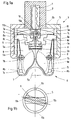
- FIG. 2b shows that in the illustration 2a the hatched locking bar just before the horizontal Close and pull position.
- Fig. 3a shows the locking element 6 and the key 1 in the Pull position or closed position of the lock 2.
- the blocking element 6 is now in the position in FIG. 2b indicated end position, in which the key 1 from the lock 2nd can be deducted.
- the locking bolt 11 is by the spring 12 arranged in the receiving pocket 11a so far upwards pressed that on the one hand the vertical leg 11b of the locking bolt 11 fully engages in the recess 10a of the key holder 10 and on the other hand, the horizontal leg 11c of the locking bolt 11 is form-fitting bears between two shoulders 8c formed on the locking arms 8, so that when the locking element 6 is completely pulled out of the holding element 5 Latching arms 8 do not release the release medium 4 into the interior of the Locking element 6 can be pressed.
- a locker key is on the one hand that the user after purchasing the Release medium 4 has the free choice of which locker he wants to use each release medium 4 is suitable for releasing each lock 3.
- the transponder held firmly in the locking element 6 can continue to be used to use other services and / or purchase food and beverages.
- purchasing the release medium 4 - which is fully automatic can be done by a pay machine - a certain amount in the To have the transponder stored, which is then gradually added to the Use of various services and / or the purchase of food and drinks are debited. It is also conceivable in the transponder to save only the use of the various services which then to be paid when leaving the sports or leisure facility or from User’s account.
- the locking element 6 is either on the locking element 6 or the key 1 one Labeling, which is also located on lock 2 or on the cabinet.
- the release of the release medium and the unlocking of the lock 2 takes place in the order of the figures Fig. 3a, 2a and 1a.
- Locking bolt 11 through the guide pins 2b of the lock 2 from the Cutout 10a of the key holder 10 is pushed out again.
- the locking bolt 11 also becomes the form-fitting system of the horizontal leg 11c on the shoulders 8c of the locking arms 8 canceled so that the locking arms 8 can be pivoted inwards again.
- FIGS 7a to 8b show two embodiments of Holding elements 5 shown.
- the in Figures 7a and 7b shown holding element 5 corresponds essentially to that in the Figures Fig. 1a, 2a and 3a shown holding element. From the Illustrations can be seen that in the illustrated embodiment, the Holding element 5 only in the rotation range of the locking element 6 or Key 1 on the end face 5c has the edge 5d and also the full Height is formed. Through this formation of partial recesses 5e in the body of the holding element 5, the access and use of the Locking element 6 facilitated by the user.
- Holding element 5 has the holding element 5 only approximately half the height of the in 7a and 7b shown holding element.
- Embodiment of the holding element 5 is the anti-rotation of Locking element 6 within the holding element 5 only through the key Latches 8a of the locking arms 8 causes.
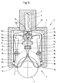
- the release medium 4 from only partially entering the blocking element 6 used and after turning the locking element 6 from the Open position pulled out of this are inside Shell surface 5a of the holding element 5 shortly before reaching the Pull-off position formed additional longitudinal grooves 5b into which the locking lugs 8a intervene if there is no release medium in the blocking element 6, as shown in Figs. 9a and 9b.
Landscapes
- Physics & Mathematics (AREA)
- General Physics & Mathematics (AREA)
- Lock And Its Accessories (AREA)
- Switches With Compound Operations (AREA)
- Electrophonic Musical Instruments (AREA)
- Control Of Vending Devices And Auxiliary Devices For Vending Devices (AREA)
Abstract
Description
- Fig. 1a
- einen Längsschnitt durch eine erfindungsgemäße Vorrichtung in der Offenstellung des Schlosses ohne eingesetztes Freigabemedium;
- Fig. 1b
- eine Vorderansicht der Vorrichtung gemäß Fig. 1a;
- Fig. 1c
- einen Längsschnitt gemäß Fig. 1a, jedoch mit teilweise eingesetztem Freigabemedium;
- Fig. 2a
- einen Längsschnitt durch die Vorrichtung gemäß Fig. 1a, jedoch mit in das Sperrelement eingesetztem Freigabemedium und den Schlüssel in einer verdrehten Stellung kurz vor der Schließstellung darstellend;
- Fig. 2b
- eine Vorderansicht der Vorrichtung gemäß Fig. 2a;
- Fig. 3a
- einen Längsschnitt durch die Vorrichtung gemäß Fig. 1a und 2a, jedoch den Schlüssel in der Abziehstellung darstellend;
- Fig. 3b
- eine Vorderansicht der Vorrichtung gemäß Fig. 3a;
- Fig. 4a
- eine Draufsicht auf das Sperrelement ohne Rastarme;
- Fig. 4b
- einen Schnitt entlang der Schnittlinie IVb-IVb gemäß Fig. 4a;
- Fig. 5
- eine Draufsicht auf einen Sperriegel;
- Fig. 6a
- eine Seitenansicht eines Schlosses;
- Fig. 6b
- eine Vorderansicht des Schlosses gemäß Fig. 6a;
- Fig. 7a
- einen Längsschnitt durch eine erste Ausführungsform eines erfindungsgemäßen Halteelements;
- Fig. 7b
- eine Draufsicht auf das Halteelement gemäß Fig. 7a;
- Fig. 8a
- einen Längsschnitt durch eine zweite Ausführungsform eines erfindungsgemäßen Halteelements;
- Fig. 8b
- eine Draufsicht auf das Halteelement gemäß Fig. 8a;
- Fig. 9a
- einen Längsschnitt durch eine erfindungsgemäßen Vorrichtung mit einem Halteelement gemäß Fig. 8a und 8b kurz vor der Abziehstellung, jedoch mit entferntem Freigabemedium und
- Fig. 9b
- eine Vorderansicht der Vorrichtung gemäß Fig. 9a.
- 1
- Schlüssel
- 2a
- Stirnfläche
- 2b
- Führungsstift
- 3
- Sperre
- 4
- Freigabemedium
- 5
- Halteelement
- 5a
- innere Mantelfläche
- 5b
- Längsnut/Ausnehmung
- 5c
- Stirnfläche
- 5d
- Rand
- 5e
- Aussparung
- 6
- Sperrelement
- 6a
- Aufnahmeraum
- 7
- Gehäuse
- 7a
- Gehäusegrundfläche
- 7b
- Drehpunkt
- 7c
- Öffnung
- 7d
- Einführöffnung
- 7e
- Führung
- 7f
- Durchgangsöffnung
- 8
- Rastarm
- 8a
- Rastnase
- 8b
- Rastnase
- 8c
- Absatz
- 9
- Federelement
- 10
- Schlüsselaufnahme
- 10a
- Aussparung
- 11
- Sperriegel
- 11a
- Aufnahmetasche
- 11b
- vertikaler Schenkel
- 11c
- horizontaler Schenkel
- 12
- Feder
Claims (21)
- Vorrichtung zur Freigabe eines Schlüssels, insbesondere eines Spindschlüssels, der in der Offenstellung des Schlosses mittels einer Sperre (3) im Schloß (2) gehalten ist und nur nach der Entriegelung der Sperre (3) in der Schließstellung des Schlosses aus dem Schloß (2) ziehbar ist, wobei die Entriegelung der Sperre (3) mittels eines Freigabemediums (4) erfolgt,
dadurch gekennzeichnet,
daß die Sperre (3) aus einem den Griff des Schlüssels (1) bildenden Sperrelement (6) und einem am Schloß (2) und/oder dem Türblatt befestigten, mit dem Sperrelement (6) zusammenwirkenden Halteelement (5) besteht, wobei das Freigabemedium (4) in das Sperrelement (6) einfügbar ist. - Vorrichtung nach Anspruch 1, dadurch gekennzeichnet, daß das Halteelement (5) als das Sperrelement (6) umgebende Rosette ausgebildet ist.
- Vorrichtung nach Anspruch 1 oder 2, dadurch gekennzeichnet, daß das Sperrelement (6) ein Gehäuse (7) aufweist, in dem mindestens ein um einen Drehpunkt (7b) verschwenkbarer, mit mindestens einer Rastnase (8a) versehener Rastarm (8) derart angeordnet ist, daß bei nicht bzw. nicht vollständig in das Sperrelement (6) eingeführtem Freigabemedium (4) die mindestens eine Rastnase (8a, 8b) des mindestens einen Rastarms (8) durch eine Öffnung (7c) im Gehäuse (7) des Sperrelementes (6) hindurch in mindestens eine Ausnehmung (5b) im Halteelement (5) eingreift.
- Vorrichtung nach Anspruch 3, dadurch gekennzeichnet, daß in dem Gehäuse (7) des Sperrelements (6) zwei um jeweils einen Drehpunkt (7b) verschwenkbare, mit jeweils mindestens einer Rastnase (8a, 8b) versehene Rastarme angeordnet sind.
- Vorrichtung nach Anspruch 4, dadurch gekennzeichnet, daß zwischen den beiden Rastarmen (8) mindestens ein die Rastarme (8) auseinanderdrückendes Federelement (9) angeordnet ist.
- Vorrichtung nach mindestens einem der Ansprüche 3 bis 5, dadurch gekennzeichnet, daß jeder Rastarm (8) als jeweils um einen in etwa mittig angeordneten Drehpunkt (7b) verschwenkbarer zweischenkliger Kipphebel ausgebildet ist.
- Vorrichtung nach Anspruch 6, dadurch gekennzeichnet, daß die mindestens eine Rastnase (8a, 8b) je Rastarm (8) nach außen weisend an einem freien Schenkelende eines jeden Rastarms (8) angeordnet ist.
- Vorrichtung nach Anspruch 6, dadurch gekennzeichnet, daß an beiden freien Schenkelenden eines jeden Rastarms (8) je eine nach außen weisende Rastnase (8a, 8b) angeordnet ist.
- Vorrichtung nach mindestens einem der Ansprüche 5 bis 8, dadurch gekennzeichnet, daß das Federelement (9) oberhalb der Drehpunkte (7b) der beiden Rastarme (8) angeordnet ist.
- Vorrichtung nach mindestens einem der Ansprüche 3 bis 9, dadurch gekennzeichnet, daß die Ausnehmungen (5b) im Halteelement (5) zur Aufnahme der Rastnasen (8a, 8b) als in axialer Richtung des Halteelements angeordnete Längsnuten ausgebildet sind.
- Vorrichtung nach Anspruch 10, dadurch gekennzeichnet, daß die als Längsnuten ausgebildeten Ausnehmungen (5b) zur freien Stirnfläche (5c) des Halteelements (5) hin durch einen umlaufenden Rand (5d) verschlossen sind.
- Vorrichtung nach Anspruch 11, dadurch gekennzeichnet, daß an der freien Stirnfläche (5c) des Halteelements (5) ausschließlich im Verdrehbereich des Schlüssels (1) ein eine Hinterschneidung für die Rastnasen (8a, 8b) bildender Rand (5d) ausgebildet ist.
- Vorrichtung nach mindestens einem der Ansprüche 3 bis 11, dadurch gekennzeichnet, daß auf der Gehäusegrundfläche (7a) des Sperrelements (6) eine Führung (7e) ausgebildet ist, auf der ein Sperriegel (11) in Längsrichtung des Sperrelements (6) verschiebbar angeordnet ist.
- Vorrichtung nach mindestens einem der Ansprüche 1 bis 13, dadurch gekennzeichnet, daß der Schlüssel (1) an dem einer Einführöffnung (7d) für das Freigabemedium (4) gegenüberliegenden Ende des Gehäuses (7) des Sperrelements (6) an einer Schlüsselaufnahme (10) befestigt ist.
- Vorrichtung nach Anspruch 13, dadurch gekennzeichnet, daß der Sperriegel (11) in der Draufsicht im wesentlichen T-förmig ausgebildet in Richtung auf die Schlüsselaufnahme (10) federbelastet so auf der Führung (7e) angeordnet ist, daß der vertikale Schenkel (11b) des Sperriegels (11) in eine in der Schlüsselaufnahme (10) ausgebildete Aussparung (10a) einschiebbar ist.
- Vorrichtung nach Anspruch 15, dadurch gekennzeichnet, daß an der freien Stirnfläche (2a) des Schlosses (2) mindestens ein Führungsstift (2b) derart angeordnet ist, daß dieser in die in der Schlüsselaufnahme (10) ausgebildete Aussparung (10a) hineinragt.
- Vorrichtung nach Anspruch 16, dadurch gekennzeichnet, daß an der Stirnfläche (2a) des Schlosses (2) zwei Führungsstifte (2b) beabstandet voneinander angeordnet sind.
- Vorrichtung nach mindestens einem der Ansprüche 15 bis 17, dadurch gekennzeichnet, daß der horizontale Schenkel (11c) des Sperriegels (11) bei abgezogenem Schlüssel (1) derart zwischen den Rastarmen (8) angeordnet ist, daß dieser ein Zusammendrücken der Rastarme (8) verhindert.
- Vorrichtung nach mindestens einem der Ansprüche 1 bis 18, dadurch gekennzeichnet, daß in dem Gehäuse (7) eine Durchgangsöffnung (7f) zum Durchziehen eines Haltebandes ausgebildet ist.
- Vorrichtung nach mindestens einem der Ansprüche 1 bis 19, dadurch gekennzeichnet, daß das Freigabemedium ein Transponder ist.
- Vorrichtung nach Anspruch 20, dadurch gekennzeichnet, daß der Transponder als Münze ausgebildet ist.
Priority Applications (5)
| Application Number | Priority Date | Filing Date | Title |
|---|---|---|---|
| EP97115095A EP0922822B1 (de) | 1997-09-01 | 1997-09-01 | Vorrichtung zur Freigabe eines Schlüssels |
| AT97115095T ATE186090T1 (de) | 1997-09-01 | 1997-09-01 | Vorrichtung zur freigabe eines schlüssels |
| DE59700635T DE59700635D1 (de) | 1997-09-01 | 1997-09-01 | Vorrichtung zur Freigabe eines Schlüssels |
| DK97115095T DK0922822T3 (da) | 1997-09-01 | 1997-09-01 | Anordning til frigivelse af en nøgle |
| NO983817A NO983817L (no) | 1997-09-01 | 1998-08-20 | Innretning til frigivning av en n°kkel |
Applications Claiming Priority (1)
| Application Number | Priority Date | Filing Date | Title |
|---|---|---|---|
| EP97115095A EP0922822B1 (de) | 1997-09-01 | 1997-09-01 | Vorrichtung zur Freigabe eines Schlüssels |
Publications (2)
| Publication Number | Publication Date |
|---|---|
| EP0922822A1 true EP0922822A1 (de) | 1999-06-16 |
| EP0922822B1 EP0922822B1 (de) | 1999-10-27 |
Family
ID=8227300
Family Applications (1)
| Application Number | Title | Priority Date | Filing Date |
|---|---|---|---|
| EP97115095A Expired - Lifetime EP0922822B1 (de) | 1997-09-01 | 1997-09-01 | Vorrichtung zur Freigabe eines Schlüssels |
Country Status (5)
| Country | Link |
|---|---|
| EP (1) | EP0922822B1 (de) |
| AT (1) | ATE186090T1 (de) |
| DE (1) | DE59700635D1 (de) |
| DK (1) | DK0922822T3 (de) |
| NO (1) | NO983817L (de) |
Cited By (2)
| Publication number | Priority date | Publication date | Assignee | Title |
|---|---|---|---|---|
| EP1124207A1 (de) * | 2000-02-09 | 2001-08-16 | Scheidt & Bachmann Gmbh | Schliesssystem |
| GB2413150A (en) * | 2004-04-13 | 2005-10-19 | James Patrick Hayes | Security locker for an open drink |
Citations (4)
| Publication number | Priority date | Publication date | Assignee | Title |
|---|---|---|---|---|
| EP0026745A2 (de) * | 1979-09-27 | 1981-04-08 | K. Schwizer AG | Münzbetätigte Verschliessvorrichtung |
| US4332315A (en) * | 1980-06-16 | 1982-06-01 | Ward Joseph O | Coin operated lock mechanism |
| US4433772A (en) * | 1981-06-19 | 1984-02-28 | Schulte-Schlagbaum Ag | Lock with locking function adapted to be actuated after the insertion of a coin |
| EP0766209A1 (de) * | 1995-09-29 | 1997-04-02 | Scheidt & Bachmann Gmbh | Einnahme- und Ausgabevorrichtung für runde Datenträger, z.B. münzförmige Transponder, zur Freigabe einer Sperreinrichtung für Personen oder Fahrzeuge |
-
1997
- 1997-09-01 EP EP97115095A patent/EP0922822B1/de not_active Expired - Lifetime
- 1997-09-01 AT AT97115095T patent/ATE186090T1/de not_active IP Right Cessation
- 1997-09-01 DK DK97115095T patent/DK0922822T3/da active
- 1997-09-01 DE DE59700635T patent/DE59700635D1/de not_active Expired - Lifetime
-
1998
- 1998-08-20 NO NO983817A patent/NO983817L/no not_active Application Discontinuation
Patent Citations (4)
| Publication number | Priority date | Publication date | Assignee | Title |
|---|---|---|---|---|
| EP0026745A2 (de) * | 1979-09-27 | 1981-04-08 | K. Schwizer AG | Münzbetätigte Verschliessvorrichtung |
| US4332315A (en) * | 1980-06-16 | 1982-06-01 | Ward Joseph O | Coin operated lock mechanism |
| US4433772A (en) * | 1981-06-19 | 1984-02-28 | Schulte-Schlagbaum Ag | Lock with locking function adapted to be actuated after the insertion of a coin |
| EP0766209A1 (de) * | 1995-09-29 | 1997-04-02 | Scheidt & Bachmann Gmbh | Einnahme- und Ausgabevorrichtung für runde Datenträger, z.B. münzförmige Transponder, zur Freigabe einer Sperreinrichtung für Personen oder Fahrzeuge |
Cited By (3)
| Publication number | Priority date | Publication date | Assignee | Title |
|---|---|---|---|---|
| EP1124207A1 (de) * | 2000-02-09 | 2001-08-16 | Scheidt & Bachmann Gmbh | Schliesssystem |
| GB2413150A (en) * | 2004-04-13 | 2005-10-19 | James Patrick Hayes | Security locker for an open drink |
| GB2413150B (en) * | 2004-04-13 | 2007-01-10 | James Patrick Hayes | Safety means |
Also Published As
| Publication number | Publication date |
|---|---|
| NO983817D0 (no) | 1998-08-20 |
| EP0922822B1 (de) | 1999-10-27 |
| ATE186090T1 (de) | 1999-11-15 |
| DK0922822T3 (da) | 2000-04-25 |
| DE59700635D1 (de) | 1999-12-02 |
| NO983817L (no) | 1999-03-02 |
Similar Documents
| Publication | Publication Date | Title |
|---|---|---|
| EP0974719A2 (de) | Schloss, insbesondere für eine Schliessanlage | |
| EP0301324B1 (de) | Schloss mit durch Einschub einer kodierten Karte freizugebender Schliessfunktion | |
| DE4019981A1 (de) | Verriegelungsanordnung fuer tueren | |
| EP0922822B1 (de) | Vorrichtung zur Freigabe eines Schlüssels | |
| EP0234510B1 (de) | Safe mit durch Münzeinwurf freizugebender Schliessfunktion eines Permutationsschlosses | |
| EP0572879B2 (de) | Kopplungsschloss für Einkaufswagen | |
| EP0550546B1 (de) | Kassenlade für eine registrierkasse | |
| DE19528250C2 (de) | Verfahren zur Freigabe eines Spindschlosses durch Einführen eines Freigabemediums in den Griff des Spindschlüssels | |
| DE69717288T2 (de) | Verschlussvorrichtung | |
| DE69831311T2 (de) | Kartenschloss | |
| DE202005019656U1 (de) | Fallenverschluß | |
| DE10329414B4 (de) | Schließvorrichtung | |
| EP0838567B1 (de) | Elektrisch gesteuertes Wertfachschloss | |
| DE2238602C3 (de) | Schloß mit durch Münzeinwurf freizugebender Schließfunktion | |
| DE69300170T2 (de) | Pfandvorrichtung und damit versehene an seinesgleichen schachtelbare Einkaufswagen. | |
| CH658736A5 (de) | Banknotenkassette. | |
| DE10246441A1 (de) | Schwenkgriff | |
| DE102005026930B4 (de) | Vorhangschloss | |
| EP1124207B1 (de) | Schliesssystem | |
| DE4235805C1 (de) | Schloß | |
| DE2808391A1 (de) | Verriegelungseinrichtung mit einer kurzzeit-entriegelungsvorrichtung fuer einen wertbehaelter | |
| DE3605859A1 (de) | Safe mit durch muenzeinwurf freizugebender schliessfunktion eines permutationsschlosses | |
| EP3418986B1 (de) | Hebelschloss | |
| DE565008C (de) | Selbstkassierende Schreibmaschine | |
| DE2836485A1 (de) | Schloss mit nach muenzeinwurf zu betaetigender schliessfunktion |
Legal Events
| Date | Code | Title | Description |
|---|---|---|---|
| GRAG | Despatch of communication of intention to grant |
Free format text: ORIGINAL CODE: EPIDOS AGRA |
|
| GRAG | Despatch of communication of intention to grant |
Free format text: ORIGINAL CODE: EPIDOS AGRA |
|
| GRAH | Despatch of communication of intention to grant a patent |
Free format text: ORIGINAL CODE: EPIDOS IGRA |
|
| GRAH | Despatch of communication of intention to grant a patent |
Free format text: ORIGINAL CODE: EPIDOS IGRA |
|
| PUAI | Public reference made under article 153(3) epc to a published international application that has entered the european phase |
Free format text: ORIGINAL CODE: 0009012 |
|
| 17P | Request for examination filed |
Effective date: 19980131 |
|
| AK | Designated contracting states |
Kind code of ref document: A1 Designated state(s): AT BE CH DE DK ES FI FR GB GR IE IT LI LU MC NL PT SE |
|
| GRAA | (expected) grant |
Free format text: ORIGINAL CODE: 0009210 |
|
| AK | Designated contracting states |
Kind code of ref document: B1 Designated state(s): AT CH DE DK FR LI NL |
|
| REF | Corresponds to: |
Ref document number: 186090 Country of ref document: AT Date of ref document: 19991115 Kind code of ref document: T |
|
| REG | Reference to a national code |
Ref country code: CH Ref legal event code: NV Representative=s name: E. BLUM & CO. PATENTANWAELTE Ref country code: CH Ref legal event code: EP |
|
| REF | Corresponds to: |
Ref document number: 59700635 Country of ref document: DE Date of ref document: 19991202 |
|
| REG | Reference to a national code |
Ref country code: IE Ref legal event code: FG4D Free format text: GERMAN |
|
| ET | Fr: translation filed | ||
| AKX | Designation fees paid |
Free format text: AT CH DE DK FR LI NL |
|
| REG | Reference to a national code |
Ref country code: DK Ref legal event code: T3 |
|
| PLBE | No opposition filed within time limit |
Free format text: ORIGINAL CODE: 0009261 |
|
| STAA | Information on the status of an ep patent application or granted ep patent |
Free format text: STATUS: NO OPPOSITION FILED WITHIN TIME LIMIT |
|
| 26N | No opposition filed | ||
| REG | Reference to a national code |
Ref country code: IE Ref legal event code: FD4D |
|
| PGFP | Annual fee paid to national office [announced via postgrant information from national office to epo] |
Ref country code: DK Payment date: 20070914 Year of fee payment: 11 |
|
| REG | Reference to a national code |
Ref country code: CH Ref legal event code: PFA Owner name: SCHEIDT & BACHMANN GMBH Free format text: SCHEIDT & BACHMANN GMBH#BREITE STRASSE 132#D-41238 MOENCHENGLADBACH (DE) -TRANSFER TO- SCHEIDT & BACHMANN GMBH#BREITE STRASSE 132#D-41238 MOENCHENGLADBACH (DE) |
|
| PGFP | Annual fee paid to national office [announced via postgrant information from national office to epo] |
Ref country code: CH Payment date: 20070914 Year of fee payment: 11 Ref country code: AT Payment date: 20070917 Year of fee payment: 11 |
|
| PGFP | Annual fee paid to national office [announced via postgrant information from national office to epo] |
Ref country code: NL Payment date: 20070913 Year of fee payment: 11 |
|
| PGFP | Annual fee paid to national office [announced via postgrant information from national office to epo] |
Ref country code: FR Payment date: 20070914 Year of fee payment: 11 |
|
| REG | Reference to a national code |
Ref country code: CH Ref legal event code: PL |
|
| REG | Reference to a national code |
Ref country code: DK Ref legal event code: EBP |
|
| PG25 | Lapsed in a contracting state [announced via postgrant information from national office to epo] |
Ref country code: NL Free format text: LAPSE BECAUSE OF NON-PAYMENT OF DUE FEES Effective date: 20090401 |
|
| NLV4 | Nl: lapsed or anulled due to non-payment of the annual fee |
Effective date: 20090401 |
|
| REG | Reference to a national code |
Ref country code: FR Ref legal event code: ST Effective date: 20090529 |
|
| PG25 | Lapsed in a contracting state [announced via postgrant information from national office to epo] |
Ref country code: AT Free format text: LAPSE BECAUSE OF NON-PAYMENT OF DUE FEES Effective date: 20080901 |
|
| PG25 | Lapsed in a contracting state [announced via postgrant information from national office to epo] |
Ref country code: LI Free format text: LAPSE BECAUSE OF NON-PAYMENT OF DUE FEES Effective date: 20080930 Ref country code: FR Free format text: LAPSE BECAUSE OF NON-PAYMENT OF DUE FEES Effective date: 20080930 Ref country code: CH Free format text: LAPSE BECAUSE OF NON-PAYMENT OF DUE FEES Effective date: 20080930 |
|
| PG25 | Lapsed in a contracting state [announced via postgrant information from national office to epo] |
Ref country code: DK Free format text: LAPSE BECAUSE OF NON-PAYMENT OF DUE FEES Effective date: 20090331 |
|
| PGFP | Annual fee paid to national office [announced via postgrant information from national office to epo] |
Ref country code: DE Payment date: 20110912 Year of fee payment: 15 |
|
| PG25 | Lapsed in a contracting state [announced via postgrant information from national office to epo] |
Ref country code: DE Free format text: LAPSE BECAUSE OF NON-PAYMENT OF DUE FEES Effective date: 20130403 |
|
| REG | Reference to a national code |
Ref country code: DE Ref legal event code: R119 Ref document number: 59700635 Country of ref document: DE Effective date: 20130403 |