EP0922827A1 - Gegenläufiges Treibstangengetriebe mit Offset-Getriebekasten - Google Patents
Gegenläufiges Treibstangengetriebe mit Offset-Getriebekasten Download PDFInfo
- Publication number
- EP0922827A1 EP0922827A1 EP98123608A EP98123608A EP0922827A1 EP 0922827 A1 EP0922827 A1 EP 0922827A1 EP 98123608 A EP98123608 A EP 98123608A EP 98123608 A EP98123608 A EP 98123608A EP 0922827 A1 EP0922827 A1 EP 0922827A1
- Authority
- EP
- European Patent Office
- Prior art keywords
- section
- drive
- leg
- converter
- flat
- Prior art date
- Legal status (The legal status is an assumption and is not a legal conclusion. Google has not performed a legal analysis and makes no representation as to the accuracy of the status listed.)
- Granted
Links
- 230000033001 locomotion Effects 0.000 claims abstract description 53
- 230000005540 biological transmission Effects 0.000 claims description 16
- 239000011521 glass Substances 0.000 claims description 5
- 238000009434 installation Methods 0.000 claims description 5
- 230000008878 coupling Effects 0.000 claims description 2
- 238000010168 coupling process Methods 0.000 claims description 2
- 238000005859 coupling reaction Methods 0.000 claims description 2
- 210000002414 leg Anatomy 0.000 description 37
- 210000000689 upper leg Anatomy 0.000 description 2
- 240000006240 Linum usitatissimum Species 0.000 description 1
- 238000005452 bending Methods 0.000 description 1
- 230000015572 biosynthetic process Effects 0.000 description 1
- 238000006243 chemical reaction Methods 0.000 description 1
- 230000000295 complement effect Effects 0.000 description 1
- 239000002184 metal Substances 0.000 description 1
- 229920000642 polymer Polymers 0.000 description 1
Images

Classifications
-
- E—FIXED CONSTRUCTIONS
- E05—LOCKS; KEYS; WINDOW OR DOOR FITTINGS; SAFES
- E05C—BOLTS OR FASTENING DEVICES FOR WINGS, SPECIALLY FOR DOORS OR WINDOWS
- E05C9/00—Arrangements of simultaneously actuated bolts or other securing devices at well-separated positions on the same wing
- E05C9/04—Arrangements of simultaneously actuated bolts or other securing devices at well-separated positions on the same wing with two sliding bars moved in opposite directions when fastening or unfastening
- E05C9/041—Arrangements of simultaneously actuated bolts or other securing devices at well-separated positions on the same wing with two sliding bars moved in opposite directions when fastening or unfastening with rack and pinion mechanism
Definitions
- the technical field of the invention are counter-rotating transmissions for use in a front recess of a wing.
- the box in which the gearbox is arranged is L-shaped and its two legs, one of which is longer, are flatter Shape, from which the definition of the term "gear box with L-shaped Gestalt "results.
- This gear is driven by an operating handle, which by a corresponding recess with a polygonal rod through the long leg of the flat L gearbox engages.
- EP-A 501 803 (Regent Lock) for controlling "shooting bolts" 21, 22 in FIG. 4 shows a counter-rotating gearbox, but with its elongated cuboid gearbox is very voluminous is.
- GB 2,277,958 (Plus Plan) discloses two flat gear boxes, each with an L-shaped shape, one of which fulfills the (non-opposite) drive of the continuous drive rod and the other of which converts an extended movement of an extended drive rod section.
- the rotary converter transmits the opposite longitudinal movements of the two-part drive rod
- the rotary converter is in the short leg of the L gearbox rotatably mounted, preferably perpendicularly below the axis in which the Operating handle is used to operate the transmission in opposite directions, so that both axes come to lie in a plane perpendicular to the connecting rod plane.
- the drive movement for the rotary converter can either be directly from the linear tooth piece can be transferred to the rotary converter or else indirectly applied via the drive rod.
- On the other side of the Rotational motion converter becomes a comparable linear tooth piece arranged that the rotational movement of the rotary converter back into a translates linear movement in the opposite direction.
- the linear tooth pieces can be insert parts (claim 4) on the side of the Rotation converter wear a linear tooth section.
- the insert on the Side of the pinion section to the actuating handle has a second tooth section on the other side of the flat insert; the insert on the side the opposing working rail has only one for recess in the The shape of the drive rail to ensure that the movement is positive or non-positive Exercise longitudinally on the second drive rail.
- tooth pieces are each also bent sections of the drive rods themselves, so that the inserts do not have to be manufactured separately, but more integrated Are part of a respective drive rail.
- the gearing to this rotary converter can be narrower than that Tooth between the operating handle and one of the two linear Tooth pieces.
- the structure in the short leg of the counter-rotating gearbox has two layers in two superimposed levels, the level of the driving rails in which these work in opposite directions, and the level of the motion converter directly below the Driving rail (claim 9).
- a compensating piece On both sides of the pinion towards the two Driving rails can be provided a compensating piece, which is also so can be extended that a continuous cover rail directly below the opposing driving rails results (claim 10).
- the cover rail is held in the gear box, interrupted by a flat one Gearbox, in which the pinion implements the direction of movement of one The drive rod near the other drive rod.
- This room should be the one Have the height of the pinion to allow a smooth rotation, so that the thickness of the pinion should be adapted to the thickness of the cover rail (Claim 2).
- the design of the drive rails in the gearbox is point-symmetrical to the axis the rotary converter (claim 7). So two identical drive rods can be used as opposing drive rods are used.
- the formation of the respective end of a connecting rod can be carried out in two stages respective edge or edge (claim 8), wherein one of the steps in the direction the longitudinal movement B, E a taper for entry into the flat leg of the Gear box and the second stage on the outward-facing side the flat linear tooth piece absorbs positive force to move the Apply driving rod.
- the other edge of the drive rail is clearer graded so that about half the original width of the respective drive rail except for the two drive rails in the middle area of the gearbox, to run parallel above the flat gear space of the motion converter, see above that the gearbox half from one and half from the other drive rail is covered.
- the two drive rails mesh and complement each other through the action of the directly adjacent motion converter extended or retracted in opposite directions.
- the other edge also has one of the first Step of the first edge transversely opposite step of the same dimension. Of the The gearbox does not stick out to the side compared to the drive rod width.
- the assembly of the transmission according to the invention is preferably carried out with frame profiles or wing profiles made of plastic or metal and can be used both with swivel wings can also be used with bottom-hung sashes with a horizontal or vertical axis.
- the counter-rotating transmission according to the invention is suitable for both Use of exposed (exposed) drive rails, as well as for those that are still covered by a cover rail. Because of the small width or the low thickness of the longer leg can be the inventive Gear in its installation depth can be varied almost arbitrarily, so that it space-saving between the surface of the frame and the front end area of the wing area insert is able to place.
- the long leg of the transmission extend far into the frame profile, almost to the inside Edge. Frame profile cavities can be filled with a high fill factor, with others Words, the frame profile may be flatter and less voluminous.
- Figure 1a illustrates the axis 100, in which a handle is inserted into the long leg 1a of the L-shaped housing 1, which can be seen in cross section from Figure 1b.
- the short leg 1b of the same flat housing can be seen in FIG. 1b, in it a second axis 102 is provided, in which a motion converter works as a flat pinion 30.
- the movement converter as a rotation converter 30 can be seen in FIG. 1a in its movement space shown there by recessing the edge of the short leg, the two compensating pieces 40b, 40a can be seen more clearly from the exploded view in FIG .
- a flat moves Insert 21 in a direction A, so that a first implementation of a rotary movement in a linear motion.
- This linear movement A is from the flat one Drive rod 10a added to a first movement component B in one Direction of locking or unlocking.
- With the movement of the flat tooth piece 21 is on the underside of the second toothing Rotation converter 30 actuated, which is set into a rotary movement C when the first drive rail 10a moves linearly.
- the gearbox is housed in the L-shaped box, which is a flat short Has leg 1b and a flat long leg 1a, the overall shape Is L-shaped, so that there is no overall box-shaped training, but an offset of the long leg with respect to the axis 102 of the short Thigh.
- Level E10 is located directly above move the drive rails 10a, 10b in opposite directions.
- FIG. 1b shows the two tooth pieces 21, 22, with a lower second one Tooth piece 22 runs only in the short leg, while the other higher Tooth piece 21 with the tooth areas arranged on both ends of its surface runs both in the short leg 1b and in the long leg 1a.
- the respective angular housing plates 1a ', 1a “and 1b', 1b” are from Figure 2 in their essential shape can be seen, two flat housing plates 1a ', 1a “and 1b ', 1b "give one of the two legs 1a, 2a of the L gearbox, the respective longitudinal end face by further angling the respective plate is covered.
- the width of the drive rails outside the short leg about the width of the finished short leg of the Gearbox corresponds.
- One is in the flat leg of the gear housing further gradation is provided, which ensures that two gear rods in the Level E10 come to lie side by side and in opposite directions in this level are movable.
- the second gradation viewed from the outside in and on the mutually facing inner edges of the two flat bars 10a, 10b at least half the width of the flat rails 10a, 10b, so that for one like that other of the two flat rails will get the same shape, despite being different directed direction of movement.
- the two flat Driving rods 10a, 10b are also two axially successive gradations intended; the one gradation corresponds to the previously described first Gradation when entering the short leg of the flat case, the second Recess corresponds to the linear tooth piece inserted vertically, to form-fit the force from a rotary movement into a linear movement or vice versa.
- the linear Tooth pieces also formed by bending directly and in one piece from the drive rods be, so that no separate insert parts are required.
- the two short shims 40a, 40b can be lengthways in the manner be elongated so that it is continuous outside the flat leg Forms cover rail for the adjacent opposing drive rods 10a, 10b.
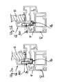
- Figure 3a and Figure 3b show installation options of the flat counter-rotating gear with the long leg 1a to clearly behind the front end of the wing surface insert E, which will usually be a glass pane.
- the sash profile S in both representations is made of plastic and the clearance F or the area between the fixed frame R (fixed frame) and the movable sash S takes up the short leg 1b.
- the conversion of the rotary movement in the axis 100 into an opposite longitudinal movement of the drive rails 10a, 10b which is not shown in more detail in these figures, does not take place in the sash frame and also not in the groove of the sash frame, but outside the profile, in the air gap area F.
Landscapes
- Engineering & Computer Science (AREA)
- Mechanical Engineering (AREA)
- Transmission Devices (AREA)
Abstract
Description
- Figur 1a
- ist eine Teilansicht eines auseinandergenommenen gegenläufigen Getriebes mit nur noch einer Treibstange 10a und der Achse 100, in der ein nicht dargestellter Betätigungsgriff zum formschlüssigen Eingriff in einen Sektor-Ritzelabschnitt 20 mit Aufnahme 19 eingesteckt wird.
- Figur 1b
- ist ein Schnitt eines Gehäuses 1 mit L-förmige Gestalt, bei dem die beiden Gehäuseschenkel, der lange Schenkel 1a und der kurze Schenkel 1b sehr flach ausgestaltet sind. Dargestellt ist die schon erwähnte Achse 100 zum Einsetzen des Betätigungsgriffes und die dazu senkrechte Achse 102 eines Rotations-Umsetzers 30 am Boden des flachen Schenkels, der die zum Falz zeigende Gehäuseplatte darstellt.
- Figur 2
- ist eine auseinandergenommen dargestellte Zusammenstellung aller Funktionselemente eines gegenläufigen Getriebes mit zwei gegenläufig arbeitenden Treibstangen 10a,10b, deren jeweilige Bewegungsrichtung B und E durch Pfeile symbolisiert ist.
- Figur 3a, Figur 3b
- sind ausschnittsweise Darstellungen eines Querschnitts der Einbauweise des L-förmigen Offset-Getriebes 1 in den Flügel S aus Kunststoff mit einer eingefügten Glasscheibe E am Glasanlageabschnitt G, welcher Flügel S im übrigen nicht ganz dargestellt ist.
Claims (12)
- Gegenläufiges Getriebe zum Einsatz in einer stirnseitigen Ausnehmung eines Flügels (S), bei dem die Ausnehmung für den im Querschnitt langen Schenkel (1a) eines im Querschnitt L-förmigen Getriebe-Flachkastens (1;1a,1b) neben und hinter das im Rahmenteil des Flügels (S) eingefügte stirnseitige Ende eines Flügel-Flächeneinsatzes (E), wie Glasscheibe, reicht, wobei(a) der im Querschnitt L-förmige Getriebe-Flachkasten (1) den langen Schenkel (1a;1a',1a") und einen kurzen Schenkel (1b;1b',1b") aufweist, welcher kurze Schenkel zwei gegenläufig in Längsrichtung bewegbare, insbesondere flache, Treibstangen (10a,10b) aufnimmt;(b) im langen Schenkel (1a) ein Ritzelabschnitt (20) drehgelagert ist, der mit einem Bewegungsumsetzer (21) im Eingriff steht, mit dem die eine (10a) der Treibstangen (10a,10b) in Längsrichtung bewegbar ist, um die Längsbewegung dieser Treibstange (10a) über einen im kurzen Schenkel (1b) gelagerten Rotations-Umsetzer (30;C), insbesondere auf der - von dem Ritzelabschnitt (20) abgewandten - Seite der einen Treibstange (10a), in eine gegenläufige Längsbewegung der anderen Treibstange (10b) umzusetzen.
- Getriebe nach Anspruch 1, bei dem der Rotations-Umsetzer (30) ein Zahnritzel ist, insbesondere etwa einer Deckschienen (40a,40b) entsprechenden Stärke, die oberhalb der Treibschienen fest im kurzen Schenkel (1b) angeordnet sind.
- Getriebe nach einem voriger Ansprüche, bei dem von den beiden Treibstangen (10a,10b) lineare Zahnstücke (21,22) ausgehen, die eine lineare Bewegung (B, E, D, A) in eine Rotationsbewegung (C) des Rotations-Umsetzers (30) bzw. vice versa vornehmen - bei Betätigung des Ritzelabschnitts (20).
- Getriebe nach Anspruch 3, bei dem das eine und/oder das andere lineare Zahnstück (21,22) ein flaches Einsatzstück ist bzw. sind, einsteckbar bzw. eingesteckt in passende Ausnehmung(en) der Treibstange(n).
- Getriebe nach Anspruch 3, bei dem mindestens eines, bevorzugt beide Zahnstücke (21, 22) im Winkel von etwa 90° abgebogene Abschnitte der jeweiligen Treibstange (10a,10b) sind.
- Getriebe nach einem der vorigen Ansprüche, bei dem das als erster Bewegungsumsetzer arbeitende lineare Zahnstück (21) nahe dem Ritzelabschnitt (20), insbesondere einem Kreissektor-Ritzelabschnitt mit bevorzugt 30° bis 60° Sektorausschnitt, längsverschieblich ist, wobei es eine zum Ritzelabschnitt bzw. Ritzelsektor (20) hin gröbere Zahnung aufweist, als zum Rotations-Umsetzer (30) auf der anderen Flachseite der einen Treibstange (10a).
- Getriebe nach einem voriger Ansprüche, bei dem die Treibstangen (10a,10b) gegenüber dem Rotations-Umsetzer (30) bzw. dessen Lagerstelle im wesentlichen rotationssymmetrisch ausgebildet sind.
- Getriebe nach einem voriger Ansprüche, bei dem(a) die jeweils zur Außenseite des Flachkastens (1) zeigenden Ränder der Treibschienen (10a,10b) doppelt gestuft sind, einmal um stufig verjüngt in den kurzen Schenkel (1b) einzulaufen und ein zweites Mal, um das Zahnstück (21,22) in einer weiter nach innen ausgerichteten Aussparung aufzunehmen; und/oder(b) die jeweils nach innen weisenden Ränder der Treibschienen (10a,10b) im kurzen Schenkel (1b) des Getriebe-Flachkastens eine innere Stufe (11a,11b) haben, die etwa der Hälfte der Treibschienenbreite entspricht, so daß in diesem Bereich zwei Treibschienen in derselben Ebene (E10) nebeneinander im kurzen Schenkel (1b) angeordnet sind.
- Getriebe nach einem voriger Ansprüche, bei dem im kurzen Schenkel (1b) zwei flache Ausgleichsstücke (40a,40b) auf beiden in Längsrichtung liegenden Seiten des Rotations-Umsetzers (30) angeordnet sind, die in einer zweiten Ebene (E40) liegen, die unterhalb derjenigen Ebene (E10) der beiden Treibstangen (10a, 10b) liegt und die in etwa die Stärke des Rotations-Umsetzers (30) haben, insbesondere geringfügig stärker sind, um dem Rotations-Umsetzer (30) eine reibungsfreie Drehbewegung zwischen den Treibstangen und der Gehäuseplatte zu ermöglichen.
- Getriebe nach Anspruch 9, bei dem die flachen Ausgleichsstücke (40a,40b) in Längsrichtung so verlängert sind, daß sich eine Deckschiene beidseits des Getriebe-Flachkastens (1) ergibt, wobei die Deckschiene und die beiden Treibstangen (10a, 10b) unmittelbar übereinander verlaufen.
- Gegenläufiges Getriebe zum Einbau in einer stirnseitigen Ausnehmung eines Flügels (S), bei dem die Ausnehmung für einen im Querschnitt langen Schenkel (1a) eines im Querschnitt L-förmigen Getriebe-Flachkastens (1;1a,1b) neben und hinter das im Rahmenteil des Flügels (S) eingefügte stirnseitige Ende eines Flügel-Flächeneinsatzes (E) reicht, wobei dadurch gekennzeichnet, daß(a) der im Querschnitt L-förmige Flachkasten (1) den langen Schenkel (1a) und einen kurzen Schenkel (1b) besitzt, welcher kurze Schenkel zwei in Längsrichtung bewegbare Treibstangen (10a,10b) aufnimmt;(b) im langen Schenkel (1a) ein von einem Betätigungsgriff durchsetzbarer Ritzelabschnitt (20) drehbar gelagert ist, der mit einem ersten Bewegungsumsetzer (21) im Eingriff steht, mit dem die eine (10a) der Treibstangen (10a,10b) in Längsrichtung bewegbar ist (A,B);(c) die Treibstangen (10a,10b) sich im kurzen Schenkel (1b) durchgehend in derselben Ebene (E10) liegend erstrecken, längsbeweglich geführt und gegenläufig betätigbar (B,E) sind; wobei die Längsbewegung der einen Treibstange (10a,B) über einen Rotations-Umsetzer (30,C) auf der - von dem Ritzelabschnitt (20) abgewandten - Seite der einen Treibstange (10a) in die gegenläufige Längsbewegung (E) der anderen Treibstange (10b) umsetzbar ist.
- Gegenläufiges Getriebe zum Einbau in einer stirnseitigen Ausnehmung eines Flügels (S), bei dem die Ausnehmung für einen im Querschnitt langen Schenkel (1a) eines im Querschnitt L-förmigen Getriebe-Flachkastens (1;1a,1b) neben und hinter das im Rahmenteil des Flügels (S) eingefügte stirnseitige Ende eines Flügel-Flächeneinsatzes (E) reicht, wobei(a) der im Querschnitt L-förmige Flachkasten (1) den langen Schenkel (1a) und einen kurzen Schenkel (1b) besitzt, welcher kurze Schenkel zwei in Längsrichtung gegenläufig bewegbare Treibstangen (10a,10b) aufnimmt;(b) im langen Schenkel (1a) ein von einem Betätigungsgriff durchsetzbarer Koppelabschnitt (20) drehbar gelagert ist, mit dem die eine (10a) der Treibstangen (10a,10b) in der einen Längsrichtung bewegbar ist (A,B);(c) die Längsbewegung der einen Treibstange (10a,B) über einen im kurzen Schenkel (1b) gelagerten Rotations-Umsetzer (30,C) in die gegenläufige Längsbewegung (E) der anderen Treibstange (10b) umsetzbar ist.
Applications Claiming Priority (2)
| Application Number | Priority Date | Filing Date | Title |
|---|---|---|---|
| DE1997154880 DE19754880C5 (de) | 1997-12-10 | 1997-12-10 | Gegenläufiges Getriebe mit Offset-Getriebekasten |
| DE19754880 | 1997-12-10 |
Publications (2)
| Publication Number | Publication Date |
|---|---|
| EP0922827A1 true EP0922827A1 (de) | 1999-06-16 |
| EP0922827B1 EP0922827B1 (de) | 2006-06-14 |
Family
ID=7851446
Family Applications (1)
| Application Number | Title | Priority Date | Filing Date |
|---|---|---|---|
| EP19980123608 Expired - Lifetime EP0922827B1 (de) | 1997-12-10 | 1998-12-10 | Gegenläufiges Treibstangengetriebe mit Offset-Getriebekasten |
Country Status (2)
| Country | Link |
|---|---|
| EP (1) | EP0922827B1 (de) |
| DE (2) | DE19754880C5 (de) |
Cited By (3)
| Publication number | Priority date | Publication date | Assignee | Title |
|---|---|---|---|---|
| WO2005021908A1 (de) * | 2003-08-22 | 2005-03-10 | Siegenia-Aubi Kg | Treibstangenverschluss |
| GB2378982B (en) * | 2001-08-23 | 2006-02-22 | Trojan Hardware & Designs Ltd | Drive mechanism for shoot bolts |
| US11454054B2 (en) * | 2016-09-08 | 2022-09-27 | Nifco Inc. | Lock device |
Citations (3)
| Publication number | Priority date | Publication date | Assignee | Title |
|---|---|---|---|---|
| FR2335678A1 (fr) * | 1975-12-19 | 1977-07-15 | Siegenia Frank Kg | Mecanisme inversant le sens de poussee pour des espagnolettes a tiges de retenue |
| GB2252351A (en) * | 1991-01-15 | 1992-08-05 | Crompton Ltd | Operating mechanism for espagnolette fastening systems |
| GB2289709A (en) * | 1994-04-22 | 1995-11-29 | Derek King | Espagnolette operating mechanism |
Family Cites Families (2)
| Publication number | Priority date | Publication date | Assignee | Title |
|---|---|---|---|---|
| DE69207792D1 (de) * | 1991-02-28 | 1996-03-07 | Regent Lock Co Ltd | Treibstangenverschlussmechanismus |
| GB9309703D0 (en) * | 1993-05-12 | 1993-06-23 | Plus Plan Uk Ltd | Locking system for doors and windows |
-
1997
- 1997-12-10 DE DE1997154880 patent/DE19754880C5/de not_active Expired - Fee Related
-
1998
- 1998-12-10 DE DE59813596T patent/DE59813596D1/de not_active Expired - Lifetime
- 1998-12-10 EP EP19980123608 patent/EP0922827B1/de not_active Expired - Lifetime
Patent Citations (3)
| Publication number | Priority date | Publication date | Assignee | Title |
|---|---|---|---|---|
| FR2335678A1 (fr) * | 1975-12-19 | 1977-07-15 | Siegenia Frank Kg | Mecanisme inversant le sens de poussee pour des espagnolettes a tiges de retenue |
| GB2252351A (en) * | 1991-01-15 | 1992-08-05 | Crompton Ltd | Operating mechanism for espagnolette fastening systems |
| GB2289709A (en) * | 1994-04-22 | 1995-11-29 | Derek King | Espagnolette operating mechanism |
Cited By (3)
| Publication number | Priority date | Publication date | Assignee | Title |
|---|---|---|---|---|
| GB2378982B (en) * | 2001-08-23 | 2006-02-22 | Trojan Hardware & Designs Ltd | Drive mechanism for shoot bolts |
| WO2005021908A1 (de) * | 2003-08-22 | 2005-03-10 | Siegenia-Aubi Kg | Treibstangenverschluss |
| US11454054B2 (en) * | 2016-09-08 | 2022-09-27 | Nifco Inc. | Lock device |
Also Published As
| Publication number | Publication date |
|---|---|
| DE19754880A1 (de) | 1999-06-24 |
| DE59813596D1 (de) | 2006-08-24 |
| DE19754880C5 (de) | 2004-10-21 |
| DE19754880C2 (de) | 2002-10-24 |
| EP0922827B1 (de) | 2006-06-14 |
Similar Documents
| Publication | Publication Date | Title |
|---|---|---|
| DE2345496A1 (de) | Treibstangenbeschlag, insbesondere einsteck-kantengetriebe, fuer die fluegel von fenstern, tueren od. dgl | |
| EP0004325B1 (de) | Getriebe für Fenster- und Türverschlüsse od. dgl. | |
| EP0589170A1 (de) | Treibstangenbeschlag für Fenster, Türen od. dgl. | |
| EP1359273B1 (de) | Verriegelungsbeschlag an einem Fenster, einer Tür oder dergleichen, mit gegenläufig verschiebbaren Treibstangen | |
| EP0740039B1 (de) | Verfahren zur Ausstattung eines Flügels mit einem Treibstangenbeschlag | |
| EP0883723B1 (de) | Treibstangenbeschlag-montagesatz | |
| DE2557303C2 (de) | Schubrichtungs-Umkehrgetriebe für Treibstangenbeschläge | |
| EP1216335B1 (de) | Zwischengetriebe für fenster-oder türbeschlag | |
| EP0292665A2 (de) | Treibstangengetriebe für Fenster, Türen od. dgl. | |
| EP2143859B1 (de) | Verriegelungsvorrichtung | |
| DE10354185B4 (de) | Kantengetriebe | |
| EP0922827B1 (de) | Gegenläufiges Treibstangengetriebe mit Offset-Getriebekasten | |
| EP0493689A1 (de) | Treibstangenbeschlag für Fenster, Türen od.dgl. | |
| EP2735678B1 (de) | Beschlag für Fenster, Türen oder dergleichen | |
| WO2000052288A1 (de) | Fenster oder tür | |
| DE2118473C3 (de) | Getriebe für Fensterverschlüsse | |
| DE4040302C2 (de) | Betätigungsgetriebe für Fenster- und Türverschlüsse o. dgl. | |
| DE202007006223U1 (de) | Beschlag | |
| DE2725982A1 (de) | Verschlussgetriebe fuer fenster, tueren o.dgl. | |
| DE10322778B4 (de) | Treibstangenantrieb | |
| EP0784142A2 (de) | Betätigungsgetriebe für Fenster und/oder Türbeschläge mit Stell- und/oder Verriegelungsgestänge od. dgl. | |
| EP0785329B1 (de) | Betätigungsgetriebe für einen Treibstangenbeschlag | |
| DE4324584C1 (de) | Treibstangenantrieb für Fenster oder Türen | |
| DE2923460C2 (de) | Rechts und links verwendbares Drehstangenschloß | |
| DE2461228A1 (de) | Verschlussvorrichtung fuer fenster, tueren oder dergleichen |
Legal Events
| Date | Code | Title | Description |
|---|---|---|---|
| PUAI | Public reference made under article 153(3) epc to a published international application that has entered the european phase |
Free format text: ORIGINAL CODE: 0009012 |
|
| AK | Designated contracting states |
Kind code of ref document: A1 Designated state(s): DE GB IE |
|
| AX | Request for extension of the european patent |
Free format text: AL;LT;LV;MK;RO;SI |
|
| AKX | Designation fees paid | ||
| RBV | Designated contracting states (corrected) |
Designated state(s): DE GB IE |
|
| REG | Reference to a national code |
Ref country code: DE Ref legal event code: 8566 |
|
| 17P | Request for examination filed |
Effective date: 19991215 |
|
| RBV | Designated contracting states (corrected) |
Designated state(s): DE GB IE |
|
| 17Q | First examination report despatched |
Effective date: 20010123 |
|
| GRAP | Despatch of communication of intention to grant a patent |
Free format text: ORIGINAL CODE: EPIDOSNIGR1 |
|
| RAP1 | Party data changed (applicant data changed or rights of an application transferred) |
Owner name: HAUTAU GMBH |
|
| GRAS | Grant fee paid |
Free format text: ORIGINAL CODE: EPIDOSNIGR3 |
|
| GRAA | (expected) grant |
Free format text: ORIGINAL CODE: 0009210 |
|
| RAP1 | Party data changed (applicant data changed or rights of an application transferred) |
Owner name: HAUTAU GMBH |
|
| AK | Designated contracting states |
Kind code of ref document: B1 Designated state(s): DE GB IE |
|
| REG | Reference to a national code |
Ref country code: GB Ref legal event code: FG4D Free format text: NOT ENGLISH |
|
| REG | Reference to a national code |
Ref country code: IE Ref legal event code: FG4D Free format text: LANGUAGE OF EP DOCUMENT: GERMAN |
|
| REF | Corresponds to: |
Ref document number: 59813596 Country of ref document: DE Date of ref document: 20060824 Kind code of ref document: P |
|
| GBT | Gb: translation of ep patent filed (gb section 77(6)(a)/1977) |
Effective date: 20061023 |
|
| PLBE | No opposition filed within time limit |
Free format text: ORIGINAL CODE: 0009261 |
|
| STAA | Information on the status of an ep patent application or granted ep patent |
Free format text: STATUS: NO OPPOSITION FILED WITHIN TIME LIMIT |
|
| 26N | No opposition filed |
Effective date: 20070315 |
|
| PGFP | Annual fee paid to national office [announced via postgrant information from national office to epo] |
Ref country code: GB Payment date: 20101230 Year of fee payment: 13 |
|
| PGFP | Annual fee paid to national office [announced via postgrant information from national office to epo] |
Ref country code: IE Payment date: 20111116 Year of fee payment: 14 |
|
| PGFP | Annual fee paid to national office [announced via postgrant information from national office to epo] |
Ref country code: DE Payment date: 20120228 Year of fee payment: 14 |
|
| GBPC | Gb: european patent ceased through non-payment of renewal fee |
Effective date: 20121210 |
|
| REG | Reference to a national code |
Ref country code: IE Ref legal event code: MM4A |
|
| PG25 | Lapsed in a contracting state [announced via postgrant information from national office to epo] |
Ref country code: DE Free format text: LAPSE BECAUSE OF NON-PAYMENT OF DUE FEES Effective date: 20130702 Ref country code: IE Free format text: LAPSE BECAUSE OF NON-PAYMENT OF DUE FEES Effective date: 20121210 |
|
| REG | Reference to a national code |
Ref country code: DE Ref legal event code: R119 Ref document number: 59813596 Country of ref document: DE Effective date: 20130702 |
|
| PG25 | Lapsed in a contracting state [announced via postgrant information from national office to epo] |
Ref country code: GB Free format text: LAPSE BECAUSE OF NON-PAYMENT OF DUE FEES Effective date: 20121210 |