EP0922833A1 - Sicherheitsvorrichtung für eine Leiter, gegebenenfalls teleskopisch - Google Patents
Sicherheitsvorrichtung für eine Leiter, gegebenenfalls teleskopisch Download PDFInfo
- Publication number
- EP0922833A1 EP0922833A1 EP98403134A EP98403134A EP0922833A1 EP 0922833 A1 EP0922833 A1 EP 0922833A1 EP 98403134 A EP98403134 A EP 98403134A EP 98403134 A EP98403134 A EP 98403134A EP 0922833 A1 EP0922833 A1 EP 0922833A1
- Authority
- EP
- European Patent Office
- Prior art keywords
- ladder
- masts
- cursor
- support
- telescopic
- Prior art date
- Legal status (The legal status is an assumption and is not a legal conclusion. Google has not performed a legal analysis and makes no representation as to the accuracy of the status listed.)
- Granted
Links
- 230000000284 resting effect Effects 0.000 claims abstract description 4
- 210000000078 claw Anatomy 0.000 claims description 4
- 238000006073 displacement reaction Methods 0.000 claims description 4
- 230000002093 peripheral effect Effects 0.000 claims description 2
- 230000008878 coupling Effects 0.000 abstract description 4
- 238000010168 coupling process Methods 0.000 abstract description 4
- 238000005859 coupling reaction Methods 0.000 abstract description 4
- 230000006641 stabilisation Effects 0.000 description 4
- 238000011105 stabilization Methods 0.000 description 4
- 238000012423 maintenance Methods 0.000 description 3
- 239000002184 metal Substances 0.000 description 3
- 210000000056 organ Anatomy 0.000 description 2
- TVEXGJYMHHTVKP-UHFFFAOYSA-N 6-oxabicyclo[3.2.1]oct-3-en-7-one Chemical compound C1C2C(=O)OC1C=CC2 TVEXGJYMHHTVKP-UHFFFAOYSA-N 0.000 description 1
- 108010005173 SERPIN-B5 Proteins 0.000 description 1
- 102100030333 Serpin B5 Human genes 0.000 description 1
- 229910000831 Steel Inorganic materials 0.000 description 1
- 230000000903 blocking effect Effects 0.000 description 1
- 230000005611 electricity Effects 0.000 description 1
- 239000000835 fiber Substances 0.000 description 1
- 238000009434 installation Methods 0.000 description 1
- 239000004033 plastic Substances 0.000 description 1
- 239000010959 steel Substances 0.000 description 1
- 239000002023 wood Substances 0.000 description 1
Images


Classifications
-
- E—FIXED CONSTRUCTIONS
- E06—DOORS, WINDOWS, SHUTTERS, OR ROLLER BLINDS IN GENERAL; LADDERS
- E06C—LADDERS
- E06C7/00—Component parts, supporting parts, or accessories
- E06C7/42—Ladder feet; Supports therefor
- E06C7/44—Means for mounting ladders on uneven ground
-
- E—FIXED CONSTRUCTIONS
- E06—DOORS, WINDOWS, SHUTTERS, OR ROLLER BLINDS IN GENERAL; LADDERS
- E06C—LADDERS
- E06C1/00—Ladders in general
- E06C1/02—Ladders in general with rigid longitudinal member or members
- E06C1/14—Ladders capable of standing by themselves
- E06C1/16—Ladders capable of standing by themselves with hinged struts which rest on the ground
- E06C1/20—Ladders capable of standing by themselves with hinged struts which rest on the ground with supporting struts formed as poles
- E06C1/22—Ladders capable of standing by themselves with hinged struts which rest on the ground with supporting struts formed as poles with extensible, e.g. telescopic, ladder parts or struts
-
- E—FIXED CONSTRUCTIONS
- E06—DOORS, WINDOWS, SHUTTERS, OR ROLLER BLINDS IN GENERAL; LADDERS
- E06C—LADDERS
- E06C7/00—Component parts, supporting parts, or accessories
- E06C7/42—Ladder feet; Supports therefor
- E06C7/423—Ladder stabilising struts
Definitions
- the present invention relates to a device for stabilization of a ladder to the right of a blind wall or of a facade of a dwelling, of a tree, or of a post.
- This device aims to allow safe user intervention on a ladder, possibly telescopic, resting on a support, and not having points anchor.
- This device seeks to avoid displacement of the ladder on its support when it is loaded by keeping the ladder high, while ensuring lateral stabilization thereof.
- the known devices of the prior art realizing the maintenance of a possibly telescopic ladder, consist essentially of the installation of non-slip pads, especially rubber, at the top and at the base, lateral uprights constituting the ladder.
- These non-slip pads may have a bevelled surface so that the bearing surface is no longer a generator but a plan.
- some of the ladders of the prior art comprise at least one stabilization system articulated on one of the bars of the ladder and which rests on the support constituted by a wall for example.
- the ladder may also rest on a floor. victim who does not offer coplanar support to everyone amounts, and despite the possible presence of a stabilization system or skates, the stability of the scale is faulty.
- the present invention therefore aims to overcome the disadvantages of the previous devices, by proposing a device which provides lateral support for the ladder, whatever the flatness of the support and whatever the nature of the vertical bearing surface (facade wall, post, etc.), this device also making it possible to distribute or move the fulcrum of the ladder, when used on a fragile support.
- the security device for a ladder possibly telescopic, comprising at least two masts, one end of which is enclosed by a means cooperative one of the top rungs of the ladder, the other end resting on the ground in a position laterally spaced from the side uprights of said ladder, characterized in that it is provided with a crossing point including a connecting member forming a cursor, guided in translation by rollers connecting two flanges enclosing one of the masts, the cursor being additionally provided with a support formed by two legs, the latter being articulated to allow its pivoting in a direction perpendicular to the axis of translation of the cursor, in order to ensure the approximation a clevis articulated on one of the legs of the support around the other mast.
- object of the invention comprises a metallic scale 1, of wood, or of fibers, of the type possibly telescopic and can have non-slip pads 2 at the end of the side uprights constituting the scale of the non-slip pads.
- These scales are commonly used within departments maintenance of organizations or companies supply of electricity or telephone, or in the building.
- one relates to the level of one of the last bars of a scale described above, a security device 3 which guarantees the maintenance lateral when the ladder is against the top of a facade or telephone pole, electrical, or a tree, thus avoiding its rotation.
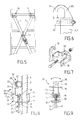
- the security device comprises at least two masts 4, 5 telescopic formed by tubes 6, 7 cooperating and sliding into each other, the latter being made from a metal or plastic profile.
- the tubes 6, 7 forming the telescopic masts 4, 5 are provided with a plurality of orifices 8 passing radially the tubes and evenly distributed over the entire length tubes 6, 7.
- FIG. 10 two tubes 6, 7 are shown, one of which is fitted with a base 36 comprising two legs protruding 37, 38, placed on either side of the tube 6 or 7.
- This base 36 is provided with an orifice 39 supporting a axis 40 coaxial with a cam 41.
- the rotation of the cam 41 around the axis 40 allows the peripheral part 42 of cam 41 comes to tangent the external wall of one tubes 6, 7.
- one of the ends of each of the masts 4, 5 telescopic is provided with a means of cooperation 10 with at least one of the upper 11 bars of the scale.
- This means of cooperation 10 is preferably carried out at using a fork 12 attached, welded or fitted, to one end of the tube 6, 7 forming the mast 4, 5 telescopic.
- this one has two claws 34, 35 forming hooks, the opening of each of them is placed head to tail on each side of the cooperation means 10.
- Each of the forks 12 encloses a bar 11 in a position which allows each of the masts 4, 5 to cross telescopic forming the safety device 3.
- the user has a member 13 which ensures the connection masts between them, this member 13 being developed using a carriage which prevents the ladder from rotating in the event of lateral fall.
- This connecting member 13 is produced for example using a stamped or welded metal part conforming to the carriage, substantially S-shaped, and which is provided clamping members 14 and a ring.
- the connecting member 13 also makes it possible, when the ladder is leaning against a post or the front of a building or dwelling, thanks to the ring, to ensure the passage of a rope (not shown in the figures) which connects the upper parts of the ladder to the uprights of the lower part.
- the connecting member 13 is shaped like a cursor.
- This comprises two flanges 15, 16, obtained by stamping of a metal strip in order to form two legs.
- These legs are interconnected via a plurality of rollers 17, in particular made of steel stainless, the latter also making it possible to space the flanges forming the cursor from a distance significantly larger than the main dimension of the cross section of the tubes forming the telescopic masts 4, 5. For example, if these tubes are of section square right, this main dimension corresponds to the edge of the tube.
- the flanges forming the cursor 13 enclose one or the other of the tubes 4, 5 forming one or the other of the masts telescopic, so that it can slide freely along these tubes.
- the rollers 17 provide both guidance and adequate positioning of the cursor 13 along the tubes 4, 5 because of their dimensions (length) and their relative positioning relative to the axis of the tube, in made on both sides of the tubes so as to frame these and limit the movements of the cursor 13 only along a translation parallel to the longitudinal axis of tubes.
- rollers 17 are mounted free to rotate on axes 18 whose ends are either riveted, either welded or bolted to the walls of each flasks.
- the cursor forming the connecting member 13 comprises at one of its ends, at the level of each of its flanges, a hinge point 19, in particular located at level of an ear zone 20, which authorizes the pivoting of a support 21 in a direction perpendicular to the translation axis of the cursor 13.
- This support 21 is shaped substantially in a square formed of two parts 22, 23, one 23 of them located in the extension of the axis of the tubes 4, 5, the other 22 being perpendicular thereto.
- This last part 22 is provided with an orifice 24 cooperating at the level of a threaded rod 25.
- the other end 26 of the rod 25 cooperates at a orifice in a swivel mounted base 27 between the two flanges 15, 16 of the cursor 13.
- This set 22, 24, 25, 26, 27 acts in the manner of a screw nut system, the threaded rod 25 moving within the orifice made in the base 27 in order to be able, depending on the race, to allow angular displacement of the support 21 around its axis articulation 19 made between the two flanges 15, 16.
- the organ of attachment 13 comprises at the support 21 a holding means 28 with one of the tubes forming one of the masts 4, 5.
- This holding means 28 mainly comprises a yoke 29 of locking conformed in U.
- This yoke 29 is articulated by conventional means at the end of one of the legs 23 constituting the support 21.
- the parts 30, 31 projecting at the level of clevis 29 articulated are lengths different and especially the lower part 31 is longer than the upper part 30 so that allow when cursor 13 is approached to one of tubes 4, 5, the self-positioning of the yoke 29 around the section of the tube, the upper part 30 disappearing during the translation of the cursor 13 and due to the angular offset of the support 23.
- an elastically deformable member of the spring type 32 which facilitates the opening or the angular pivoting of the support 21 in order to release the yoke 29 from the tube 4 or 5 initially held to release the cursor stroke 13.
- a stud 33 perpendicular to the axis of the rod, so as to provide a means to transmit a couple, in one way or another, to the threaded rod thanks to an external member (not shown in the figures), of the cane type.
- This stud 33 can be replaced in particular by any other equivalent coupling means, of the spline type, ball bearing, etc.
- the telescopic masts 4, 5 have a length greater than that corresponding to the height of the carriage relative to the ground, in order to force the user to position the lower end of the telescopic masts on the ground in a configuration which deviates laterally from the base of the lateral uprights of the ladder so as to provide lateral stability to the assembly.
- the ladder thus installed can also be fitted of a "MASPIN” type lifeline, starting from the top to the ground, on which an anti-fall device slides freely as long as no stress transmitted by the individual connected to it does not intervene.
- the lateral uprights of the ladder are fitted with cleats which ensure in the lower part additional security thanks to a rope which joins, by means of these cleats, the ladder to the support.
- the cane which transmits the torque to the rod 25 of the slider 13 and which also allows convey it along the tube this operation can be performed by the user directly from the ground, without having to climb the ladder for the sake of safety, is positioned at rest between the two masts and cooperates in particular with cam systems.
Landscapes
- Engineering & Computer Science (AREA)
- Mechanical Engineering (AREA)
- Ladders (AREA)
Priority Applications (1)
| Application Number | Priority Date | Filing Date | Title |
|---|---|---|---|
| EP03291250A EP1338753B1 (de) | 1997-12-12 | 1998-12-11 | Klemmvorrichtung zum Einstellen der Verschiebung zwischen zwei Rohren |
Applications Claiming Priority (2)
| Application Number | Priority Date | Filing Date | Title |
|---|---|---|---|
| FR9715793 | 1997-12-12 | ||
| FR9715793A FR2772422B1 (fr) | 1997-12-12 | 1997-12-12 | Dispositif de securisation pour echelle, eventuellement telescopique |
Related Child Applications (1)
| Application Number | Title | Priority Date | Filing Date |
|---|---|---|---|
| EP03291250A Division EP1338753B1 (de) | 1997-12-12 | 1998-12-11 | Klemmvorrichtung zum Einstellen der Verschiebung zwischen zwei Rohren |
Publications (2)
| Publication Number | Publication Date |
|---|---|
| EP0922833A1 true EP0922833A1 (de) | 1999-06-16 |
| EP0922833B1 EP0922833B1 (de) | 2004-03-03 |
Family
ID=9514549
Family Applications (2)
| Application Number | Title | Priority Date | Filing Date |
|---|---|---|---|
| EP03291250A Expired - Lifetime EP1338753B1 (de) | 1997-12-12 | 1998-12-11 | Klemmvorrichtung zum Einstellen der Verschiebung zwischen zwei Rohren |
| EP19980403134 Expired - Lifetime EP0922833B1 (de) | 1997-12-12 | 1998-12-11 | Sicherheitsvorrichtung für eine Leiter, gegebenenfalls teleskopisch |
Family Applications Before (1)
| Application Number | Title | Priority Date | Filing Date |
|---|---|---|---|
| EP03291250A Expired - Lifetime EP1338753B1 (de) | 1997-12-12 | 1998-12-11 | Klemmvorrichtung zum Einstellen der Verschiebung zwischen zwei Rohren |
Country Status (4)
| Country | Link |
|---|---|
| EP (2) | EP1338753B1 (de) |
| DE (2) | DE69822094T2 (de) |
| ES (2) | ES2217520T3 (de) |
| FR (1) | FR2772422B1 (de) |
Families Citing this family (2)
| Publication number | Priority date | Publication date | Assignee | Title |
|---|---|---|---|---|
| FR2990988B1 (fr) * | 2012-05-28 | 2014-05-23 | Aud Innov | Dispositif de stabilisation d'une echelle par des jambes telescopiques |
| US11698092B2 (en) | 2020-06-22 | 2023-07-11 | Unger Marketing International | Telescopic pole for a cleaning implement |
Citations (4)
| Publication number | Priority date | Publication date | Assignee | Title |
|---|---|---|---|---|
| DE474422C (de) * | 1929-04-04 | Fischer Ernst | Leiterstuetze zur Herstellung einer Bockleiter aus einer gewoehnlichen Leiter | |
| GB488228A (en) * | 1936-03-31 | 1938-07-04 | William Chew | An improved step ladder, trestle and the like |
| US3269486A (en) * | 1964-07-27 | 1966-08-30 | James F Machen | Ladder holder |
| US5542497A (en) * | 1994-11-14 | 1996-08-06 | Macyszyn; Witold S. | Ladder level adjusting attachment |
Family Cites Families (1)
| Publication number | Priority date | Publication date | Assignee | Title |
|---|---|---|---|---|
| US5511632A (en) * | 1994-07-25 | 1996-04-30 | Ermis; Jerry J. | Ladder with auxiliary support |
-
1997
- 1997-12-12 FR FR9715793A patent/FR2772422B1/fr not_active Expired - Lifetime
-
1998
- 1998-12-11 EP EP03291250A patent/EP1338753B1/de not_active Expired - Lifetime
- 1998-12-11 DE DE69822094T patent/DE69822094T2/de not_active Expired - Lifetime
- 1998-12-11 DE DE69835108T patent/DE69835108T2/de not_active Expired - Lifetime
- 1998-12-11 ES ES98403134T patent/ES2217520T3/es not_active Expired - Lifetime
- 1998-12-11 EP EP19980403134 patent/EP0922833B1/de not_active Expired - Lifetime
- 1998-12-11 ES ES03291250T patent/ES2268295T3/es not_active Expired - Lifetime
Patent Citations (4)
| Publication number | Priority date | Publication date | Assignee | Title |
|---|---|---|---|---|
| DE474422C (de) * | 1929-04-04 | Fischer Ernst | Leiterstuetze zur Herstellung einer Bockleiter aus einer gewoehnlichen Leiter | |
| GB488228A (en) * | 1936-03-31 | 1938-07-04 | William Chew | An improved step ladder, trestle and the like |
| US3269486A (en) * | 1964-07-27 | 1966-08-30 | James F Machen | Ladder holder |
| US5542497A (en) * | 1994-11-14 | 1996-08-06 | Macyszyn; Witold S. | Ladder level adjusting attachment |
Also Published As
| Publication number | Publication date |
|---|---|
| EP0922833B1 (de) | 2004-03-03 |
| ES2268295T3 (es) | 2007-03-16 |
| DE69822094T2 (de) | 2005-03-31 |
| ES2217520T3 (es) | 2004-11-01 |
| DE69835108T2 (de) | 2007-02-01 |
| DE69835108D1 (de) | 2006-08-10 |
| DE69822094D1 (de) | 2004-04-08 |
| FR2772422A1 (fr) | 1999-06-18 |
| FR2772422B1 (fr) | 2000-02-11 |
| EP1338753A1 (de) | 2003-08-27 |
| EP1338753B1 (de) | 2006-06-28 |
Similar Documents
| Publication | Publication Date | Title |
|---|---|---|
| EP1069067A1 (de) | Wirbelöse zum Heben von Lasten | |
| EP1087098B1 (de) | Sicherheitsvorrichtung | |
| EP0922833B1 (de) | Sicherheitsvorrichtung für eine Leiter, gegebenenfalls teleskopisch | |
| EP1094175B1 (de) | Befestigungsvorrichtung für Diagonalstreben an Gerüstleitern und damit hergestelltes Gerüst | |
| FR3108599A1 (fr) | Dispositif de stabilisation d’un élévateur vertical d’une personne | |
| FR2909398A1 (fr) | Dispositif de securite applique aux appareils de levage de panneaux au niveau des plafonds et murs | |
| EP1302607A1 (de) | Hebevorrichtung zur Montage von Platten an einer Unterdecke | |
| EP2700064B1 (de) | Vorrichtung zum aufhängen einer markise | |
| FR2482542A1 (fr) | Mecanisme de commande de frein a main | |
| FR2941650A1 (fr) | Dispositif adapte pour la pose de papier au plafond | |
| FR2711109A1 (fr) | Chevalet pour le montage et l'entretien d'une bicyclette. | |
| FR2680196A1 (fr) | Dispositif d'assemblage et de fixation d'une extremite d'une traverse a un montant et systeme d'echafaudage comprenant des traverses munies a chacune de leurs extremites d'un tel dispositif. | |
| FR2912451A1 (fr) | Dispositif formant mat vertical de support d'au moins un element, tel qu'une antenne de transmission d'ondes radioelectriques ou une camera video de surveillance. | |
| FR2847916A1 (fr) | Coeur de croisement a pointe mobile | |
| EP0282385B1 (de) | Vorrichtung zur Verankerung an Dachsparren bei Dacharbeiten | |
| FR2773680A1 (fr) | Parapluie ou parasol a mat excentre | |
| FR2623241A1 (fr) | Dispositif d'ancrage d'une echelle sur un angle de poteau | |
| FR2580902A1 (fr) | Dispositif d'accrochage, notamment pour la suspension de quartiers de viande. | |
| FR2532674A1 (fr) | Dispositif de securite pour echafaudage | |
| FR2598041A1 (fr) | Dispositif de relevage et de supportage temporaire de cable | |
| FR2772421A1 (fr) | Dispositif de securisation pour echelle | |
| FR2683619A1 (fr) | Dispositif d'eclairage en tres basse tension avec rail support. | |
| FR2956424A1 (fr) | Plateforme de travail en encorbellement | |
| FR2903716A1 (fr) | Banche pourvue d'une plateforme de circulation a verrouillage automatique en position de service | |
| FR2990988A1 (fr) | Dispositif de stabilisation d'une echelle par des jambes telescopiques |
Legal Events
| Date | Code | Title | Description |
|---|---|---|---|
| PUAI | Public reference made under article 153(3) epc to a published international application that has entered the european phase |
Free format text: ORIGINAL CODE: 0009012 |
|
| AK | Designated contracting states |
Kind code of ref document: A1 Designated state(s): DE ES FR GB IT |
|
| AX | Request for extension of the european patent |
Free format text: AL;LT;LV;MK;RO;SI |
|
| 17P | Request for examination filed |
Effective date: 19991027 |
|
| AKX | Designation fees paid |
Free format text: DE ES FR GB IT |
|
| 17Q | First examination report despatched |
Effective date: 20030121 |
|
| GRAP | Despatch of communication of intention to grant a patent |
Free format text: ORIGINAL CODE: EPIDOSNIGR1 |
|
| GRAS | Grant fee paid |
Free format text: ORIGINAL CODE: EPIDOSNIGR3 |
|
| GRAA | (expected) grant |
Free format text: ORIGINAL CODE: 0009210 |
|
| AK | Designated contracting states |
Kind code of ref document: B1 Designated state(s): DE ES FR GB IT |
|
| REG | Reference to a national code |
Ref country code: GB Ref legal event code: FG4D Free format text: NOT ENGLISH |
|
| REF | Corresponds to: |
Ref document number: 69822094 Country of ref document: DE Date of ref document: 20040408 Kind code of ref document: P |
|
| GBT | Gb: translation of ep patent filed (gb section 77(6)(a)/1977) |
Effective date: 20040624 |
|
| REG | Reference to a national code |
Ref country code: ES Ref legal event code: FG2A Ref document number: 2217520 Country of ref document: ES Kind code of ref document: T3 |
|
| PLBE | No opposition filed within time limit |
Free format text: ORIGINAL CODE: 0009261 |
|
| STAA | Information on the status of an ep patent application or granted ep patent |
Free format text: STATUS: NO OPPOSITION FILED WITHIN TIME LIMIT |
|
| 26N | No opposition filed |
Effective date: 20041206 |
|
| REG | Reference to a national code |
Ref country code: FR Ref legal event code: PLFP Year of fee payment: 18 |
|
| REG | Reference to a national code |
Ref country code: FR Ref legal event code: PLFP Year of fee payment: 19 |
|
| REG | Reference to a national code |
Ref country code: FR Ref legal event code: PLFP Year of fee payment: 20 |
|
| PGFP | Annual fee paid to national office [announced via postgrant information from national office to epo] |
Ref country code: DE Payment date: 20171120 Year of fee payment: 20 Ref country code: FR Payment date: 20171121 Year of fee payment: 20 |
|
| PGFP | Annual fee paid to national office [announced via postgrant information from national office to epo] |
Ref country code: GB Payment date: 20171121 Year of fee payment: 20 Ref country code: IT Payment date: 20171120 Year of fee payment: 20 |
|
| PGFP | Annual fee paid to national office [announced via postgrant information from national office to epo] |
Ref country code: ES Payment date: 20180103 Year of fee payment: 20 |
|
| REG | Reference to a national code |
Ref country code: DE Ref legal event code: R071 Ref document number: 69822094 Country of ref document: DE |
|
| REG | Reference to a national code |
Ref country code: GB Ref legal event code: PE20 Expiry date: 20181210 |
|
| PG25 | Lapsed in a contracting state [announced via postgrant information from national office to epo] |
Ref country code: GB Free format text: LAPSE BECAUSE OF EXPIRATION OF PROTECTION Effective date: 20181210 |
|
| REG | Reference to a national code |
Ref country code: ES Ref legal event code: FD2A Effective date: 20200804 |
|
| PG25 | Lapsed in a contracting state [announced via postgrant information from national office to epo] |
Ref country code: ES Free format text: LAPSE BECAUSE OF EXPIRATION OF PROTECTION Effective date: 20181212 |