EP0922865B1 - Blindniet für die Befestigung eines Gestells auf einer Kunststoffplatte - Google Patents
Blindniet für die Befestigung eines Gestells auf einer Kunststoffplatte Download PDFInfo
- Publication number
- EP0922865B1 EP0922865B1 EP98122748A EP98122748A EP0922865B1 EP 0922865 B1 EP0922865 B1 EP 0922865B1 EP 98122748 A EP98122748 A EP 98122748A EP 98122748 A EP98122748 A EP 98122748A EP 0922865 B1 EP0922865 B1 EP 0922865B1
- Authority
- EP
- European Patent Office
- Prior art keywords
- base
- tab
- blind rivet
- slot
- legs
- Prior art date
- Legal status (The legal status is an assumption and is not a legal conclusion. Google has not performed a legal analysis and makes no representation as to the accuracy of the status listed.)
- Expired - Lifetime
Links
- 239000011800 void material Substances 0.000 claims 3
- 238000003780 insertion Methods 0.000 description 3
- 230000037431 insertion Effects 0.000 description 3
- 239000002184 metal Substances 0.000 description 3
- 238000000034 method Methods 0.000 description 2
- 239000000463 material Substances 0.000 description 1
- 238000010079 rubber tapping Methods 0.000 description 1
- 238000000926 separation method Methods 0.000 description 1
Images


Classifications
-
- H—ELECTRICITY
- H01—ELECTRIC ELEMENTS
- H01H—ELECTRIC SWITCHES; RELAYS; SELECTORS; EMERGENCY PROTECTIVE DEVICES
- H01H71/00—Details of the protective switches or relays covered by groups H01H73/00 - H01H83/00
- H01H71/02—Housings; Casings; Bases; Mountings
- H01H71/0264—Mountings or coverplates for complete assembled circuit breakers, e.g. snap mounting in panel
-
- F—MECHANICAL ENGINEERING; LIGHTING; HEATING; WEAPONS; BLASTING
- F16—ENGINEERING ELEMENTS AND UNITS; GENERAL MEASURES FOR PRODUCING AND MAINTAINING EFFECTIVE FUNCTIONING OF MACHINES OR INSTALLATIONS; THERMAL INSULATION IN GENERAL
- F16B—DEVICES FOR FASTENING OR SECURING CONSTRUCTIONAL ELEMENTS OR MACHINE PARTS TOGETHER, e.g. NAILS, BOLTS, CIRCLIPS, CLAMPS, CLIPS OR WEDGES; JOINTS OR JOINTING
- F16B19/00—Bolts without screw-thread; Pins, including deformable elements; Rivets
- F16B19/04—Rivets; Spigots or the like fastened by riveting
- F16B19/08—Hollow rivets; Multi-part rivets
- F16B19/10—Hollow rivets; Multi-part rivets fastened by expanding mechanically
-
- F—MECHANICAL ENGINEERING; LIGHTING; HEATING; WEAPONS; BLASTING
- F16—ENGINEERING ELEMENTS AND UNITS; GENERAL MEASURES FOR PRODUCING AND MAINTAINING EFFECTIVE FUNCTIONING OF MACHINES OR INSTALLATIONS; THERMAL INSULATION IN GENERAL
- F16B—DEVICES FOR FASTENING OR SECURING CONSTRUCTIONAL ELEMENTS OR MACHINE PARTS TOGETHER, e.g. NAILS, BOLTS, CIRCLIPS, CLAMPS, CLIPS OR WEDGES; JOINTS OR JOINTING
- F16B2200/00—Constructional details of connections not covered for in other groups of this subclass
- F16B2200/40—Clamping arrangements where clamping parts are received in recesses of elements to be connected
-
- Y—GENERAL TAGGING OF NEW TECHNOLOGICAL DEVELOPMENTS; GENERAL TAGGING OF CROSS-SECTIONAL TECHNOLOGIES SPANNING OVER SEVERAL SECTIONS OF THE IPC; TECHNICAL SUBJECTS COVERED BY FORMER USPC CROSS-REFERENCE ART COLLECTIONS [XRACs] AND DIGESTS
- Y10—TECHNICAL SUBJECTS COVERED BY FORMER USPC
- Y10T—TECHNICAL SUBJECTS COVERED BY FORMER US CLASSIFICATION
- Y10T403/00—Joints and connections
- Y10T403/49—Member deformed in situ
- Y10T403/4958—Separate deforming means remains with joint assembly
-
- Y—GENERAL TAGGING OF NEW TECHNOLOGICAL DEVELOPMENTS; GENERAL TAGGING OF CROSS-SECTIONAL TECHNOLOGIES SPANNING OVER SEVERAL SECTIONS OF THE IPC; TECHNICAL SUBJECTS COVERED BY FORMER USPC CROSS-REFERENCE ART COLLECTIONS [XRACs] AND DIGESTS
- Y10—TECHNICAL SUBJECTS COVERED BY FORMER USPC
- Y10T—TECHNICAL SUBJECTS COVERED BY FORMER US CLASSIFICATION
- Y10T403/00—Joints and connections
- Y10T403/49—Member deformed in situ
- Y10T403/4966—Deformation occurs simultaneously with assembly
Definitions
- the present invention relates to fasteners, generally and in particular to the use of a deformable fastener to attach a metal frame to a plastic base.
- the subject invention is embodied in a method of attaching the mechanical frame of a circuit breaker to a base portion of a circuit breaker housing. While the invention is described in terms of the circuit breaker mechanical frame, it is contemplated that it may be practiced in any of a number of applications in which a first member having a flat tab which is perpendicular to a second member is joined by the tab to the second member.
- the holding power of the screw into the cross-section of the mechanical frame may not be sufficient to adequately secure the mechanical frame to the plastic base and may permit torsion of the mechanical frame or other forms of movement which may affect the operation of the breaker.
- US-A-4003107 describes a one piece plastic pin fastener to secure a circuit board to a receptacle.
- apparatus for securing an object to a base comprises a flat, generally rectangular tab mechanically attached to the object, the tab having first and second legs extending from the object which first and second legs define a generally U-shaped opening in the tab, each leg having an interior edge and an exterior edge, the interior edges of the legs being separated from one another by a predetermined distance; and a blind rivet having a head portion and a body portion, the head portion being generally circular in shape and having a diameter greater than the predetermined distance, the body portion being generally cylindrical in shape and having a diameter less than the predetermined distance; wherein the base includes a generally circular opening having a diameter approximately equal to the predetermined distance, whereby, when the blind rivet is inserted through the opening in the base and into the U-shaped opening in the tab and is mechanically upset, the body portion of the blind rivet expands into the lateral groove in the tab and pulls the
- the first member includes an opening into which a deformable fastener is inserted after first passing through the second member.
- the fastener retains the first member to the second member by expanding into the opening in the first member as the deformable fastener is mechanically upset.
- the opening in the first member includes a lateral groove which provides a volume into which the deformable fastener may flow as the fastener is mechanically upset.
- the fastener retains the first member to the second member by deformation into and around the groove, exerting a force which tends to pull the first member toward the second member.
- the opening in the first member defines a U-shaped tab having first and second legs and the opening in the second member defines a slot into which the U-shaped tab is inserted.
- At least one leg of the U shaped tab includes a tang which is pressed into the side of the slot in the second member as the legs are pushed apart by a force exerted on the legs by the fastener as the fastener is upset.
- the present invention provides substantial advantages in that it simultaneously brings the mechanical frame into firm contact with the plastic base, prevents the separation of frame from the base and, by expanding in the U-shaped slot after insertion, provides necessary force from the blind rivet to hold the frame securely to the base.
- a blind rivet also known as a pull-rivet, is a rivet which may be used to attach two workpieces by setting the rivet into an opening through both workpieces but without access to the remote or blind side of the workpieces.
- An exemplary blind rivet is disclosed in U.S. Patent No. 4,580,936 entitled "BLIND RIVET ASSEMBLY".
- the blind rivet includes a tubular shell and a stem or mandrel.
- the tubular shell has a head and an elongate shank.
- the shank includes a weakened portion, such that, when the stem or mandrel is pulled, the weakened portion of the shank collapses forming a blind head on the far side of the two members that are being joined.
- the blind rivet is used as follows. The shank is inserted into aligned apertures in the two members which are to be joined until the head of the shell rests against the opening in the near member. The stem or mandrel is then pulled, causing the weakened portion of the shank to collapse and expand annularly to form a blind head beyond the aperture in the far member.
- the stem or mandrel breaks once the applied force exceeds a threshold value with the remaining portion of the stem or mandrel forming a plug in the portion of the shank which extends through the two members.
- the blind rivet is not used to join two flat members having aligned apertures but is used to attach a perpendicular member to a horizontal member.
- the blind rivet is inserted through an opening in the flat member into a U-shaped opening in the perpendicular member.
- the blind rivet is typically set using a rivet setting tool (not shown). When the tool is activated, it rejects the blind rivet through the aperture in the horizontal member and into the U-shaped opening in the perpendicular member. It then pulls the mandrel back through the rivet thereby collapsing the rivet and making the material in the weakened shank flow into the U-shaped opening. This causes a downward pressure which pulls the perpendicular member toward the horizontal member. The mandrel then breaks away from the rivet and remains in a holder of the gun.
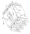
- an exemplary circuit breaker 10 includes an insulating support base 12, and cover 13.
- the mechanical frame is shown in Figure 2.
- the mechanical frame of a breaker includes the operating mechanism which is used to close the breaker contacts and a trip latch which, when activated, quickly opens the breaker contacts.
- the mechanical frame 210 includes a mounting tab 212 having a U-shaped opening 214 into which the blind rivet (shown in Figure 5) is inserted to attach the mechanical frame 210 to the circuit breaker base 12.
- the opening 214 is formed by two legs 218 and 220, each of which includes a lateral groove 216.
- the blind rivet is upset, its deformable portion expands into the lateral grooves 216 to grasp the mechanical frame 210 and exert a downward pressure on the frame causing it to be pulled into the base 12.
- Figure 3 is an isometric drawing of the base 12 with the cover 13 removed.
- the base 12 includes three chambers 310a, 310b and 310c.
- the mechanical frame 210 is inserted only into the center chamber 310b.
- the exemplary mechanical frame 210 is attached to the base 12 using two blind rivets.
- the tabs 212 of the mechanical frame (shown in Figure 2) are inserted into slots 312 (only one of which is shown in Figure 3).
- the blind rivet is inserted from the bottom side of the base 12 and upset to secure the tabs 212 into the slots 312.
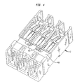
- Figure 4 is an isometric drawing showing the bottom of the base 12.
- the base includes two counterbore holes 410 into which the blind rivets are inserted in order to fasten the mechanical frame 210 to the base 12.
- Figure 5 is an exploded isometric drawing of the blind rivet 500, base 12 and mechanical frame tab 212 cutaway along the line 5-5 shown in Figure 1, which illustrates the manner in which the mechanical frame 210 is secured to the base 12.
- Figure 5 shows the initial insertion of tab 212 into the slot 312 of the base 12.
- the blind rivet 500 includes a tubular shell having a head 506, a shank 508 and a mandrel 507.
- the head, shank and mandrel are generally cylindrical in shape.
- the diameter of the mandrel is less than the diameter of the shank which is less than the diameter of the head.
- the mandrel is fixedly attached to a plug 512 which closes off the top of the shank 508. When the mandrel is pulled, it exerts a force, through the plug 512, on the shank 508, causing at least a portion of the shank to deform.
- the shank 508 of the blind rivet 500 is inserted into a cylindrical opening 518 in the slot 310 which extends through the bottom wall 400 of the circuit breaker base 12.
- the head is sized to fit within the counterbore hole 410 (shown in Figure 4) but not within the cylindrical opening 518.
- the tab 212 of the mechanical frame 210 fits into the slot 310 such that the legs 218 and 220 of the tab are on either side of the shank 508.
- the blind rivet is upset by pulling the mandrel, the shank 508 deforms and expands into the opening 216 in the tab 212 and into the lateral grooves 216 on the legs 218 and 220.
- the deforming shank is moving toward the bottom wall 400 of the base 12. As the deforming shank expands and makes contact with the tab 212, it pulls the tab deeper into the slot 312 to securely fasten the mechanical frame 210 to the base 12.
- each tab 212 of the mechanical frame 210 includes two legs, 218 and 220 which define a U-shaped opening.
- the interior edges of each leg are separated from one another by a distance which is wider than the shank 508 of the blind rivet 500 and one of the legs may include a lateral groove 216 on its inside edge.
- one leg (218) has a tang 222 extending from the outer edge of the leg, at the base of the tab.
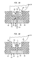
- Figures 6A and 6B are cut away drawings on the line 6 - 6 shown in Figure 5.
- Figure 6A shows the combination of the mechanical frame 210, base 12 and blind rivet 500 when the blind rivet is first inserted into the opening 518 and
- Figure 6B shows the same combination after the blind rivet is upset.
- Figure 6A shows the head 506 of the blind rivet 500 inserted into the counterbore 410 on the underside of the bottom wall 400 of the breaker base 12 such that the shank portion of the rivet 500 extends through the opening 518 and into the slot 312 between the legs 218 and 220 of the mounting tab 212.
- the shank portion 508 of the blind rivet 500 includes a weakened section 614.
- the weakened section 614 bends out, away from the mandrel, filling the space between the legs 218 and 220 of the mounting tab and filling lateral grooves 216 in the legs, as shown in Figure 6B.
- the expanding shank pushes the legs 218 and 220 apart, forcing the tang 222 into the side of the slot 312.
- the shank is deformed, it pulls the mounting tab 120 into the slot 312 and, at the same time, pulls the head 506 of the blind rivet further into the counterbore 410.
- the blind rivet 500 holds the mounting tab 212 of the mechanical frame 220 tightly against the bottom of the slot 312. This ensures that the mechanical frame 210 is held in the proper position in the base 12 of the circuit breaker 10.
Landscapes
- Breakers (AREA)
- Connection Of Plates (AREA)
Claims (5)
- Vorrichtung zur sicheren Befestigung eines Gegenstands an einer Basis (12), wobei diese Vorrichtung Folgendes beinhaltet:wobei die Basis eine in der Regel kreisförmige Öffnung (518), die einen Durchmesser hat, der ungefähr dem festgelegten Abstand entspricht, wobei sich der Körperanteil der Blindniet (500) - wenn die Blindniet (500) durch die Öffnung in der Basis (12) in die U-förmige Öffnung (214) im Vorsprung eingeführt und mechanisch gestaucht wird - in die seitliche Nut (216) im Vorsprung ausdehnt und den Gegenstand zur Basis heranzieht.einen flachen, in der Regel rechteckigen Vorsprung, der mechanisch an dem Gegenstand befestigt ist, wobei der Vorsprung (212) ein erstes und ein zweites Bein (218, 220) hat, die sich von dem Gegen-stand aus erstrecken, wobei dieses erste Bein und zweite Bein eine in der Regel U-förmige Öffnung (214) in dem Vorsprung definieren und wobei jedes Bein eine Innenkante und eine Außenkante hat, wobei die Innenkanten der Beine voneinander durch einen festgelegten Abstand getrennt sind; undeine Blindniet (500), die einen ersten Anteil (506) und einen Körperanteil hat, wobei der Kopfanteil in der Regel kreisförmig ist und einen Durchmesser hat, der größer als der festgelegte Abstand ist, wobei der Körperanteil in der Regel zylinderförmig ist und einen Durchmesser hat, der kleiner als der festgelegte Abstand ist;
- Vorrichtung nach Anspruch 1, bei der die Innenkante von mindestens einem Bein (218, 220) des Vorsprungs weiterhin eine seitliche Nut (216) beinhaltet, in die sich der Körperanteil der Blindniet (500) ausdehnt, wenn die Blindniet mechanisch so gestaucht wird, dass die Blindniet eine Zugkraft auf die seitliche Nut des Vorsprungs ausübt, während die Blindniet gestaucht wird, um den Vorsprung zur Basis (12) hin zu ziehen.
- Vorrichtung nach Anspruch 2, bei der:die Basis (12) weiterhin einen Schlitz (312) beinhaltet, in den der Vorsprung (212) eingeführt wird, wobei die kreisförmige Öffnung (518) in der Basis so mit dem Schlitz gefluchtet ist, dass sie zwischen den beiden Beinen (218, 220) des Vorsprungs ist, wenn der Vorsprung in den Schlitz eingeführt wird; unddie Außenkante von mindestens einem Bein des Vorsprungs einen Zapfen (222) beinhaltet, wobei - wenn die Blindniet gestaucht wird - der sich ausdehnende Körperanteil der Blindniet eine Kraft gegen die Innenkanten der Beine des Vorsprungs ausübt und den Zapfen gegen eine Seite des Schlitzes in der Basis zieht.
- Vorrichtung nach Anspruch 1, bei der die Basis eine Innenfläche und eine Außenfläche hat, wobei der Gegenstand an der Innenfläche der Basis zu befestigen ist und bei der die Vorrichtung weiterhin Folgendes beinhaltet: einen in der Regel rechteckigen Schlitz (310), der sich von der Innenfläche der Basis in die Basis hinein, jedoch nicht in die Außenfläche der Basis erstreckt, wobei der Schlitz einen in der Regel zylinderförmigen Hohlraum (518) mit einem festgelegten Durchmesser beinhaltet, wobei dieser Hohlraum im Schlitz zentriert ist und sich von der Außenfläche der Basis zur Innenfläche der Basis erstreckt; wobei mindestens ein Bein des Vorsprungs einen Zapfen an der Außenkante beinhaltet; und wobei die Blindniet (500) durch den Hohlraum (518) von der Außenfläche der Basis aus und der Vorsprung (212) in den Schlitz eingeführt werden, und zwar von der Innenseite der Basis (12) aus und dann in die U-förmige Öffnung (214) im Vorsprung, so dass sich der Körperanteil der Blindniet - wenn die Blindniet mechanisch gestaucht wird - in die seitliche Nut im Vorsprung ausdehnt, den Gegenstand zur Basis heranzieht und den Zapfen in eine Seite des Schlitzes drückt.
- Vorrichtung nach Anspruch 4, bei der der Gegenstand ein mechanischer Rahmen und die Basis die Basis eines Leistungsschalters ist.
Applications Claiming Priority (2)
| Application Number | Priority Date | Filing Date | Title |
|---|---|---|---|
| US08/988,415 US5906462A (en) | 1997-12-10 | 1997-12-10 | Use of a blind rivet to retain a mechanical frame into a plastic base |
| US988415 | 1997-12-10 |
Publications (3)
| Publication Number | Publication Date |
|---|---|
| EP0922865A2 EP0922865A2 (de) | 1999-06-16 |
| EP0922865A3 EP0922865A3 (de) | 2001-03-21 |
| EP0922865B1 true EP0922865B1 (de) | 2004-10-13 |
Family
ID=25534090
Family Applications (1)
| Application Number | Title | Priority Date | Filing Date |
|---|---|---|---|
| EP98122748A Expired - Lifetime EP0922865B1 (de) | 1997-12-10 | 1998-11-30 | Blindniet für die Befestigung eines Gestells auf einer Kunststoffplatte |
Country Status (3)
| Country | Link |
|---|---|
| US (1) | US5906462A (de) |
| EP (1) | EP0922865B1 (de) |
| DE (1) | DE69826968T2 (de) |
Families Citing this family (2)
| Publication number | Priority date | Publication date | Assignee | Title |
|---|---|---|---|---|
| US8284542B2 (en) * | 2010-03-09 | 2012-10-09 | Schneider Electric USA, Inc. | Circuit breaker with improved tie-down accessory |
| CN114776681B (zh) * | 2021-01-22 | 2024-03-22 | 宾科精密部件(中国)有限公司 | 铆接方法及铆接结构 |
Family Cites Families (10)
| Publication number | Priority date | Publication date | Assignee | Title |
|---|---|---|---|---|
| US2921320A (en) * | 1957-06-05 | 1960-01-19 | O A Feldon | Fixture mounting means |
| US4003107A (en) * | 1975-10-22 | 1977-01-18 | General Electric Company | One piece plastic pin fastener |
| US4245652A (en) * | 1978-10-10 | 1981-01-20 | Hamelly International, Inc. | Device and method for preventing foreign substance migration through an opening in living animal tissue |
| GB2136075B (en) * | 1983-03-07 | 1986-11-05 | Avdel Ltd | Rivet |
| US4603312A (en) * | 1985-03-21 | 1986-07-29 | Westinghouse Electric Corp. | Circuit breaker with adjustable trip unit |
| US4647264A (en) * | 1985-07-22 | 1987-03-03 | Russell, Burdsall & Ward Corporation | Sealing cap tubular rivet head and assembly |
| US4882456A (en) * | 1985-11-04 | 1989-11-21 | Cooper Industries, Inc. | Locking device for electrical switch or circuit breaker handle |
| JPS62229631A (ja) * | 1986-03-28 | 1987-10-08 | 三菱電機株式会社 | 回路しや断器 |
| US4835501A (en) * | 1987-09-11 | 1989-05-30 | Cooper Industries, Inc. | Current limiting assembly for circuit breakers |
| US4859108A (en) * | 1988-03-17 | 1989-08-22 | The B.F. Goodrich Company | Blind fastener |
-
1997
- 1997-12-10 US US08/988,415 patent/US5906462A/en not_active Expired - Lifetime
-
1998
- 1998-11-30 EP EP98122748A patent/EP0922865B1/de not_active Expired - Lifetime
- 1998-11-30 DE DE69826968T patent/DE69826968T2/de not_active Expired - Lifetime
Also Published As
| Publication number | Publication date |
|---|---|
| EP0922865A3 (de) | 2001-03-21 |
| US5906462A (en) | 1999-05-25 |
| DE69826968T2 (de) | 2005-03-10 |
| EP0922865A2 (de) | 1999-06-16 |
| DE69826968D1 (de) | 2004-11-18 |
Similar Documents
| Publication | Publication Date | Title |
|---|---|---|
| US6896460B2 (en) | Fastener | |
| US6514023B2 (en) | Removable and reusable fastener | |
| US7237314B2 (en) | Method of securing a nut plate to a wall defined by an aperture through a workpiece | |
| US8793860B2 (en) | Method for mounting a metal collar reasons for allowance | |
| US4556351A (en) | Expansion rivet assembly | |
| US5476350A (en) | Slotted push-in rivet and method of riveting | |
| EP0344005B1 (de) | Blindniet | |
| EP0958456B1 (de) | Blindniet und verfahren zu seiner herstellung | |
| US5006024A (en) | Dual-lock blind fastener | |
| US4842237A (en) | One-piece wire retainer clip mountable on threaded stud | |
| US7046207B2 (en) | Antenna mounting structure | |
| EP0725221B1 (de) | Verfahren zum Befestigen von Bauteilen einer Zusammenstellung | |
| US10738811B2 (en) | Clamping clinch fastener | |
| JPH0285510A (ja) | 自己閉塞盲締着具 | |
| CA2073724A1 (en) | Stud end pierce nut | |
| EP0515026B1 (de) | Blindbefestiger | |
| EP0922865B1 (de) | Blindniet für die Befestigung eines Gestells auf einer Kunststoffplatte | |
| US4002099A (en) | Rivet | |
| US4177710A (en) | Blind fastener | |
| EP0537967A1 (de) | Mit Kopf versehener Zapfen | |
| EP0653570A2 (de) | Blindniet mit Hülse | |
| CN113226592B (zh) | 紧固元件 | |
| JP2003172331A (ja) | ナットプレート | |
| EP1653091A1 (de) | Selbstsichernde Hohlschraubnieten | |
| JP4364978B2 (ja) | 下孔開け機構付き締結具 |
Legal Events
| Date | Code | Title | Description |
|---|---|---|---|
| PUAI | Public reference made under article 153(3) epc to a published international application that has entered the european phase |
Free format text: ORIGINAL CODE: 0009012 |
|
| AK | Designated contracting states |
Kind code of ref document: A2 Designated state(s): DE ES FR GB IT |
|
| AX | Request for extension of the european patent |
Free format text: AL;LT;LV;MK;RO;SI |
|
| 17P | Request for examination filed |
Effective date: 19991109 |
|
| PUAL | Search report despatched |
Free format text: ORIGINAL CODE: 0009013 |
|
| AK | Designated contracting states |
Kind code of ref document: A3 Designated state(s): AT BE CH CY DE DK ES FI FR GB GR IE IT LI LU MC NL PT SE |
|
| AX | Request for extension of the european patent |
Free format text: AL;LT;LV;MK;RO;SI |
|
| AKX | Designation fees paid |
Free format text: DE ES FR GB IT |
|
| 17Q | First examination report despatched |
Effective date: 20040113 |
|
| GRAP | Despatch of communication of intention to grant a patent |
Free format text: ORIGINAL CODE: EPIDOSNIGR1 |
|
| GRAS | Grant fee paid |
Free format text: ORIGINAL CODE: EPIDOSNIGR3 |
|
| GRAA | (expected) grant |
Free format text: ORIGINAL CODE: 0009210 |
|
| AK | Designated contracting states |
Kind code of ref document: B1 Designated state(s): DE ES FR GB IT |
|
| PG25 | Lapsed in a contracting state [announced via postgrant information from national office to epo] |
Ref country code: IT Free format text: LAPSE BECAUSE OF FAILURE TO SUBMIT A TRANSLATION OF THE DESCRIPTION OR TO PAY THE FEE WITHIN THE PRESCRIBED TIME-LIMIT;WARNING: LAPSES OF ITALIAN PATENTS WITH EFFECTIVE DATE BEFORE 2007 MAY HAVE OCCURRED AT ANY TIME BEFORE 2007. THE CORRECT EFFECTIVE DATE MAY BE DIFFERENT FROM THE ONE RECORDED. Effective date: 20041013 Ref country code: FR Free format text: LAPSE BECAUSE OF FAILURE TO SUBMIT A TRANSLATION OF THE DESCRIPTION OR TO PAY THE FEE WITHIN THE PRESCRIBED TIME-LIMIT Effective date: 20041013 |
|
| REG | Reference to a national code |
Ref country code: GB Ref legal event code: FG4D |
|
| REF | Corresponds to: |
Ref document number: 69826968 Country of ref document: DE Date of ref document: 20041118 Kind code of ref document: P |
|
| PG25 | Lapsed in a contracting state [announced via postgrant information from national office to epo] |
Ref country code: GB Free format text: LAPSE BECAUSE OF NON-PAYMENT OF DUE FEES Effective date: 20050113 |
|
| PG25 | Lapsed in a contracting state [announced via postgrant information from national office to epo] |
Ref country code: ES Free format text: LAPSE BECAUSE OF FAILURE TO SUBMIT A TRANSLATION OF THE DESCRIPTION OR TO PAY THE FEE WITHIN THE PRESCRIBED TIME-LIMIT Effective date: 20050124 |
|
| PLBE | No opposition filed within time limit |
Free format text: ORIGINAL CODE: 0009261 |
|
| STAA | Information on the status of an ep patent application or granted ep patent |
Free format text: STATUS: NO OPPOSITION FILED WITHIN TIME LIMIT |
|
| GBPC | Gb: european patent ceased through non-payment of renewal fee |
Effective date: 20050113 |
|
| 26N | No opposition filed |
Effective date: 20050714 |
|
| EN | Fr: translation not filed | ||
| PGFP | Annual fee paid to national office [announced via postgrant information from national office to epo] |
Ref country code: DE Payment date: 20170120 Year of fee payment: 19 |
|
| REG | Reference to a national code |
Ref country code: DE Ref legal event code: R119 Ref document number: 69826968 Country of ref document: DE |
|
| PG25 | Lapsed in a contracting state [announced via postgrant information from national office to epo] |
Ref country code: DE Free format text: LAPSE BECAUSE OF NON-PAYMENT OF DUE FEES Effective date: 20180602 |