EP0922872B1 - Schalteinrichtung für Schaltgetriebe - Google Patents
Schalteinrichtung für Schaltgetriebe Download PDFInfo
- Publication number
- EP0922872B1 EP0922872B1 EP98121630A EP98121630A EP0922872B1 EP 0922872 B1 EP0922872 B1 EP 0922872B1 EP 98121630 A EP98121630 A EP 98121630A EP 98121630 A EP98121630 A EP 98121630A EP 0922872 B1 EP0922872 B1 EP 0922872B1
- Authority
- EP
- European Patent Office
- Prior art keywords
- shaft
- pinion
- pinions
- sleeve
- shift means
- Prior art date
- Legal status (The legal status is an assumption and is not a legal conclusion. Google has not performed a legal analysis and makes no representation as to the accuracy of the status listed.)
- Expired - Lifetime
Links
Images
Classifications
-
- F—MECHANICAL ENGINEERING; LIGHTING; HEATING; WEAPONS; BLASTING
- F16—ENGINEERING ELEMENTS AND UNITS; GENERAL MEASURES FOR PRODUCING AND MAINTAINING EFFECTIVE FUNCTIONING OF MACHINES OR INSTALLATIONS; THERMAL INSULATION IN GENERAL
- F16D—COUPLINGS FOR TRANSMITTING ROTATION; CLUTCHES; BRAKES
- F16D28/00—Electrically-actuated clutches
-
- F—MECHANICAL ENGINEERING; LIGHTING; HEATING; WEAPONS; BLASTING
- F16—ENGINEERING ELEMENTS AND UNITS; GENERAL MEASURES FOR PRODUCING AND MAINTAINING EFFECTIVE FUNCTIONING OF MACHINES OR INSTALLATIONS; THERMAL INSULATION IN GENERAL
- F16D—COUPLINGS FOR TRANSMITTING ROTATION; CLUTCHES; BRAKES
- F16D21/00—Systems comprising a plurality of actuated clutches
- F16D21/02—Systems comprising a plurality of actuated clutches for interconnecting three or more shafts or other transmission members in different ways
- F16D21/04—Systems comprising a plurality of actuated clutches for interconnecting three or more shafts or other transmission members in different ways with a shaft carrying a number of rotatable transmission members, e.g. gears, each of which can be connected to the shaft by a clutching member or members between the shaft and the hub of the transmission member
Definitions
- the invention relates to a switching device for manual transmissions, comprising a first shaft on which several sprockets of different diameters are rotatably mounted, which mesh with pinions, on a second shaft are arranged in a rotationally fixed manner, and coupling elements, with which either one of the rotatable pinion is rotatably coupled to the first shaft, each of the rotatable pinion is assigned a deformable coupling element, so is dimensioned so that depending on the state of deformation unhindered rotation of the corresponding pinion in relation to the shaft allowed or connects this pinion to the shaft in a friction-locked manner.
- a switching device is already known in which the coupling element as Drawing wedge is formed.
- This switching device is therefore also called a wedge-type circuit designated.
- the pull wedge that is axially displaceable in the shaft can be positively engaged with one of the rotatably mounted pinions to connect this pinion to the shaft in a rotationally fixed manner.
- Such one Conventional gear with wedge-type gearshifting has several disadvantages afflicted. A relatively small transmissible torque is one large overall length opposite. Another disadvantage is the loud noise that arises when the pulling wedge when shifting with the desired pinion Intervention. Through this positive connection of the drawing wedge with the desired pinion is also the security of the Switching process affected.
- JP 09 014299 A is already a piezoelectric shaft coupling known comprising one or more piezoelectric elements, the on Arranged inner circumference of a hollow hub connected to a first shaft and after applying a voltage with the outer circumference one to one second shaft attached disc frictionally connect, wherein a coaxial state of the two shafts is maintained.
- the invention has for its object a generic switching device to create, with a small overall length by a large one distinguishable transmissible moment and the almost noiseless Switching process with great switching reliability.
- each coupling element a piezoelectric material, which is when applying a electric field that each coupling element extends between one outer peripheral surface of the first shaft and an inner peripheral surface of the assigned pinion arranged sleeve and / or a between a Ring shoulder of the shaft and one side surface of the assigned pinion arranged ring, and that optionally on one of the coupling elements Voltage can be applied.
- the invention takes advantage of the fact that the dielectric constant non-conductive substances from their density, i.e. from the pressure under which they are is dependent.
- the dielectric constant can increase or decrease with density. Those Substances with which it increases draw when an electrical one is put on Field together, while they expand in the other case. This as electrostriction designated phenomenon is generally the square of the field strength proportional, i.e. independent of the field direction. Materials where the Electrostriction is particularly pronounced, usually called piezoelectric Referred to materials.
- Switching device is a ceramic material as the piezoelectric material for the Coupling element particularly suitable.
- the coupling element consisting of a piezoelectric material expands in the corresponding stress state, then it exercises on the shaft and the pinion to be coupled with a clamping force so that it becomes a non-positive connection comes. Because of this positive connection can transmit a large torque with a relatively small overall length become. This positive connection can be practically noiseless and with great security can be brought about.
- the non-positive connection between the shaft and the desired one Pinion can by a radial or by an axial extension of the coupling element or by a combination thereof.
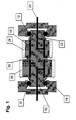
- the switching device for manual transmission shown in Fig. 1 comprises a shaft 10, which is rotatably supported by ball bearings 12 in a housing 14.
- two sleeves 18 are arranged in a rotationally fixed manner.
- the two sleeves 18 lie on the inside a radially projecting collar 20 of the shaft.
- a locking ring 22 which shrinks onto the shaft 10 is.
- the retaining ring 22 can also be connected to the shaft 10 in another way be connected, it is only important that he against axial displacement is secured.
- In the center of the shaft 10 are two power supplies 24, the each with a sleeve 18 and connected to the positive pole of a battery (not shown) are.
- the two sleeves 18 there are two pinions 26, 28 with different ones Diameter rotatably supported.
- the two pinions 26, 28 are through the collar 20 of the shaft 10 and secured by the two locking rings 22 in their axial position.
- Each of the two pinions 26, 28 meshes with an associated one (not shown) Pinion, which is non-rotatably arranged on a shaft (also not shown), which can be a driving or driving shaft.
- the two Sleeves 18 are made of a piezoelectric ceramic material that is expands when applying an electrical field. In the normal state of the sleeve 18, that is, if no electric field is applied, the assigned pinion can Turn 26 or 28 freely on the sleeve 18.
- the pinions (not shown) meshing with the two pinions 26, 28 are via the assigned shaft and the housing 14 with the negative pole of a (not shown) Battery connected.
- an electrical field is applied to the associated sleeve 18. More specifically a switch is actuated to the sleeve 18 belonging to the pinion 26 via the To connect power supply 24 to the positive pole of the battery. Under the influence of the electric field, the sleeve 18 expands radially, so that a non-positive Connection of the pinion 26 with the shaft 10 occurs. Because of the radial expansion the clamping force caused by the sleeve 18 is sufficient to produce a large torque to transmit between the shaft 10 and the pinion 26.
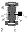
- FIG. 2 differs from that in FIG. 1 Embodiment shown essentially in that the two pinions 26, 28th are rotatably mounted directly on the shaft 10 and that between each pinion and the central collar 20 of the shaft 10, a ring 30 made of a piezoelectric Material is arranged. Like the sleeve 18, the ring 30 can be made of one Ceramic material exist that expands when an electric field is applied. Each of the two rings 30 is assigned its own sliding contact 32 which connected via a power supply 34 to the positive pole of a battery (not shown) can be. Similar to the first embodiment is in each power supply 34 a switch arranged to connect to the positive pole of the Manufacture or interrupt the battery.
- the two power supply lines 34 assigned switches can forcibly be coupled so that one of them is opened when the other is closed.
- Each of the two rings has 30 such a width that it prevents the rotation of the associated pinion 26 or 28 not obstructed relative to the shaft 10 when it is in the non-activated state located. If, however, by closing the corresponding switch on the Power supply 34 and the sliding contact 32 to one of the two rings 30 one Voltage is applied, then it expands axially. The associated pinion 26 or 28 is therefore between the axially expanded ring 30 and the opposite one Circlip 22 held frictionally. The clamping force achieved is sufficient to handle even higher torques between the shaft and the pinion transferred to.
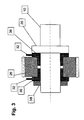
- the third embodiment shown in FIG. 3 represents a kind of Combination of the first and the broad embodiment. That assigned to each pinion Coupling element comprises two collar rings 36 arranged in mirror image L-shaped cross section. The two collar rings 36 made of a piezoelectric Material is between the central collar 20 of the shaft 10 and a locking ring 38 arranged. A sliding contact 32 is assigned to each collar ring 36. The As in the second embodiment, two sliding contacts 32 can have one Switch (not shown) can be connected to the positive pole of a battery. If this switch closed and consequently one on the two collar rings 36 Voltage is applied, then they stretch in both radial and axial Direction out.
- the associated pinion 26 is therefore both in radial and in axially clamped with the shaft 10 in a form-fitting manner. Between the pinion 26 and therefore an even greater torque can be transmitted to the shaft 10. It can be seen that in the same way a non-positive connection between the other pinion not shown in FIG. 3 and the shaft 10 can be achieved can.
- the selected pinion becomes 26 or 28 not abruptly rotatably coupled to the shaft 10, but it comes as a result of frictional connection to a slip.
- the switching process can therefore be smooth and be carried out silently.
- the resulting from the initial hatch Frictional heat can easily be dissipated because of such switching devices usually run in an oil bath.
Landscapes
- Engineering & Computer Science (AREA)
- General Engineering & Computer Science (AREA)
- Mechanical Engineering (AREA)
- Physics & Mathematics (AREA)
- Electromagnetism (AREA)
- Mechanical Operated Clutches (AREA)
- Gear-Shifting Mechanisms (AREA)
- Structure Of Transmissions (AREA)
- Arrangement Of Transmissions (AREA)
Description
- 10
- Welle
- 12
- Kugellager
- 14
- Gehäuse
- 18
- Hülse
- 20
- Bund
- 22
- Sicherungsring
- 24
- Stromzuführung
- 26
- Ritzel
- 28
- Ritzel
- 30
- Ring
- 32
- Schleifkontakt
- 34
- Stromzuführung
- 36
- Bundringe
- 38
- Sicherungsring
Claims (6)
- Schalteinrichtung für Schaltgetriebe, umfassend eine erste Welle, auf der mehrere Ritzel von unterschiedlichem Durchmesser drehbar gelagert sind, die mit Ritzeln kämmen, die auf einer zweiten Welle drehfest angeordnet sind, und Koppelelemente, mit denen wahlweise eines der drehbaren Ritzel mit der ersten Welle drehfest kuppelbar ist, wobei jedem der drehbaren Ritzel (26, 28) ein verformbares Koppelelement (18; 30; 36) zugeordnet ist, das so bemessen ist, dass es in Abhängigkeit vom Verformungszustand eine ungehinderte Verdrehung des entsprechenden Ritzels (26, 28) gegenüber der Welle (10) erlaubt oder dieses Ritzel mit der Welle kraftschlüssig verbindet, dadurch gekennzeichnet, dass jedes Koppelelement (18; 30; 36) aus einem piezoelektrischen Material besteht, das sich beim Anlegen eines elektrischen Feldes ausdehnt, dass jedes Koppelelement eine zwischen einer äußeren Umfangsfläche der ersten Welle (10) und einer inneren Umfangsfläche des zugeordneten Ritzels (26, 28) angeordnete Hülse (18) und/oder ein zwischen einer Ringschulter (20) der Welle (10) und einer Seitenfläche des zugeordneten Ritzels (26, 28) angeordneter Ring (30) ist, und dass wahlweise an eines der Koppelelemente (18; 30; 36) eine Spannung anlegbar ist.
- Schalteinrichtung nach Anspruch 1, dadurch gekennzeichnet, dass die Hülse (18) und/oder der Ring (30) auf der Welle (10) drehfest angeordnet ist.
- Schalteinrichtung nach Anspruch 1 oder 2, dadurch gekennzeichnet, dass die Hülse (18) über eine in der Welle (10) angeordnete Stromzuführung (24) mit dem Pluspol einer Batterie verbindbar ist, und dass die Ritzel (26, 28) mit dem Minuspol der Batterie in Verbindung stehen.
- Schalteinrichtung nach Anspruch 2, dadurch gekennzeichnet, dass der Ring (30) über einen Schleifkontakt (32) mit dem Pluspol einer Batterie verbindbar ist, und dass die Ritzel (26, 28) mit dem Minuspol der Batterie in Verbindung stehen.
- Schalteinrichtung nach einem der Ansprüche 1 bis 4, dadurch gekennzeichnet, dass das piezoelektrische Material ein Keramikmaterial ist.
- Schalteinrichtung nach einem der Ansprüche 1 bis 5, dadurch gekennzeichnet, dass beide Kontakte am piezoelektrischen Material angreifen.
Applications Claiming Priority (2)
| Application Number | Priority Date | Filing Date | Title |
|---|---|---|---|
| DE19754966 | 1997-12-11 | ||
| DE19754966A DE19754966A1 (de) | 1997-12-11 | 1997-12-11 | Schalteinrichtung für Schaltgetriebe |
Publications (3)
| Publication Number | Publication Date |
|---|---|
| EP0922872A2 EP0922872A2 (de) | 1999-06-16 |
| EP0922872A3 EP0922872A3 (de) | 2000-04-19 |
| EP0922872B1 true EP0922872B1 (de) | 2001-08-29 |
Family
ID=7851490
Family Applications (1)
| Application Number | Title | Priority Date | Filing Date |
|---|---|---|---|
| EP98121630A Expired - Lifetime EP0922872B1 (de) | 1997-12-11 | 1998-11-12 | Schalteinrichtung für Schaltgetriebe |
Country Status (3)
| Country | Link |
|---|---|
| EP (1) | EP0922872B1 (de) |
| JP (1) | JPH11264424A (de) |
| DE (2) | DE19754966A1 (de) |
Families Citing this family (4)
| Publication number | Priority date | Publication date | Assignee | Title |
|---|---|---|---|---|
| US6384518B1 (en) * | 2000-09-18 | 2002-05-07 | Jean A. Van Poppel | Piezoelectric coupler for variably coupling two bodies and joint incorporating the coupler |
| DE10103426A1 (de) * | 2001-01-26 | 2002-08-01 | Hydraulik Ring Gmbh | Ansteuereinrichtung für hydraulische und/oder mechanische Komponenten |
| DE10135253B4 (de) * | 2001-07-19 | 2004-07-22 | Stabilus Gmbh | Feststeller zwischen zwei relativ zueinander beweglichen Baugruppen |
| DE102004040586A1 (de) * | 2004-08-21 | 2006-02-23 | Zf Friedrichshafen Ag | Aktuator für den Antriebsstrang eines Kraftfahrzeuges |
Family Cites Families (12)
| Publication number | Priority date | Publication date | Assignee | Title |
|---|---|---|---|---|
| US4636679A (en) * | 1986-01-15 | 1987-01-13 | The United States Of America As Represented By The Secretary Of The Air Force | Piezoelectrically driven fast response high-torque clutch unit |
| DE3805710A1 (de) * | 1988-02-24 | 1989-09-07 | Achenbach Buschhuetten Gmbh | Schaltgetriebe |
| GB2223544B (en) * | 1988-03-14 | 1993-04-07 | Okuma Machinery Works Ltd | Feed-screw support structure |
| EP0342264A3 (de) * | 1988-05-07 | 1990-11-28 | Warner France | Elektrische Kupplungs- oder Bremsvorrichtung |
| DE3842397A1 (de) * | 1988-12-16 | 1990-06-21 | Audi Ag | Vorrichtung zum unterbrechen des kraftschlusses zwischen zwei bauteilen |
| RU2031280C1 (ru) * | 1991-05-28 | 1995-03-20 | Валерий Владимирович Дюдин | Коробка передач |
| DE4445606B4 (de) * | 1994-01-05 | 2004-02-12 | Luk Lamellen Und Kupplungsbau Beteiligungs Kg | Betätigungsvorrichtung |
| JP2914165B2 (ja) * | 1994-03-11 | 1999-06-28 | 日産自動車株式会社 | 電気制御運動伝達方法および運動伝達装置 |
| DE19512642A1 (de) * | 1995-04-05 | 1996-10-10 | Bayerische Motoren Werke Ag | Schaltgetriebe |
| JPH0914299A (ja) * | 1995-07-05 | 1997-01-14 | Ricoh Co Ltd | 圧電クラッチ |
| DE19538978C1 (de) * | 1995-10-19 | 1996-11-21 | Univ Magdeburg Tech | Antriebseinheit zur Erzeugung vorzugsweise rotatorischer Abtriebsbewegungen, insbesondere mittels piezoelektrischer Aktoren |
| DE19627145C2 (de) * | 1996-07-05 | 2003-05-28 | Andreas Hilker | Kupplung |
-
1997
- 1997-12-11 DE DE19754966A patent/DE19754966A1/de not_active Withdrawn
-
1998
- 1998-11-12 EP EP98121630A patent/EP0922872B1/de not_active Expired - Lifetime
- 1998-11-12 DE DE59801301T patent/DE59801301D1/de not_active Expired - Fee Related
- 1998-12-10 JP JP10351592A patent/JPH11264424A/ja active Pending
Also Published As
| Publication number | Publication date |
|---|---|
| DE19754966A1 (de) | 1999-09-09 |
| EP0922872A3 (de) | 2000-04-19 |
| EP0922872A2 (de) | 1999-06-16 |
| JPH11264424A (ja) | 1999-09-28 |
| DE59801301D1 (de) | 2001-10-04 |
Similar Documents
| Publication | Publication Date | Title |
|---|---|---|
| DE4314887C2 (de) | Kegelrad-Differenzialgetriebe | |
| DE69903385T2 (de) | Synchronisierte Schaltvorrichtung für ein Verteilergetriebe | |
| DE69710554T2 (de) | Synchronisierte Bereichsschalteinrichtung für zweistufiges Verteilergetriebe | |
| EP1257752B1 (de) | Elektromagnetische schalteinrichtung | |
| DE69107008T2 (de) | Drehantrieb mit innenverzahntem Planetenrad-Untersetzungsgetriebe und Freilaufeinrichtung. | |
| DE4343048A1 (de) | Differential mit begrenztem Schlupf | |
| DE10335193A1 (de) | Selektiv sperrbare Differentialbaugruppe für ein Kraftfahrzeug | |
| WO2007076795A1 (de) | Schaltkupplung für prothesen | |
| DE3626822A1 (de) | Gangschaltungs- und kupplungsvorrichtung | |
| DE10141862A1 (de) | Differential mit Schlupfbegrenzung | |
| DE10147969B4 (de) | Ausgleichsgetriebevorrichtung vom Planetengetriebetyp | |
| EP0922872B1 (de) | Schalteinrichtung für Schaltgetriebe | |
| EP0521268A2 (de) | Rutschkupplung | |
| DE102007014831B4 (de) | Kupplungsaktuatorik mit einer Unterstützungseinrichtung und Kupplung mit einer solchen Kupplungsaktuatorik | |
| EP1582758B1 (de) | Kupplungsvorrichtung mit Klemmkörpern | |
| WO2012072394A1 (de) | Aktuator | |
| DE202005017525U1 (de) | Reibungskupplung | |
| CH689005A5 (de) | Antriebseinheit mit einer Fliehkraftkupplung. | |
| EP2018493A1 (de) | Getriebevorrichtung zum verteilen eines antriebsmomentes auf wenigstens zwei abtriebswellen | |
| DE2353983C3 (de) | Schaltbare Reibungskupplung mit drehmomentabhängiger Anpreflkraft | |
| AT401282B (de) | Schaltgetriebe | |
| DE69800362T2 (de) | Flüssigkeitsreibungsbetätigte Kugel-Rampen-Kupplung | |
| DE69801031T2 (de) | Synchronisiereinrichtung | |
| DE102019124150A1 (de) | Mechanische Stellanzeige und elektrischer Stellantrieb | |
| EP3405692B1 (de) | Getriebewelle, bauteilpaarung und verfahren zum betrieb einer getriebewelle |
Legal Events
| Date | Code | Title | Description |
|---|---|---|---|
| PUAI | Public reference made under article 153(3) epc to a published international application that has entered the european phase |
Free format text: ORIGINAL CODE: 0009012 |
|
| AK | Designated contracting states |
Kind code of ref document: A2 Designated state(s): DE FR IT |
|
| AX | Request for extension of the european patent |
Free format text: AL;LT;LV;MK;RO;SI |
|
| PUAL | Search report despatched |
Free format text: ORIGINAL CODE: 0009013 |
|
| AK | Designated contracting states |
Kind code of ref document: A3 Designated state(s): AT BE CH CY DE DK ES FI FR GB GR IE IT LI LU MC NL PT SE |
|
| AX | Request for extension of the european patent |
Free format text: AL;LT;LV;MK;RO;SI |
|
| 17P | Request for examination filed |
Effective date: 20000316 |
|
| 17Q | First examination report despatched |
Effective date: 20001023 |
|
| AKX | Designation fees paid |
Free format text: DE FR IT |
|
| GRAG | Despatch of communication of intention to grant |
Free format text: ORIGINAL CODE: EPIDOS AGRA |
|
| GRAG | Despatch of communication of intention to grant |
Free format text: ORIGINAL CODE: EPIDOS AGRA |
|
| GRAG | Despatch of communication of intention to grant |
Free format text: ORIGINAL CODE: EPIDOS AGRA |
|
| GRAH | Despatch of communication of intention to grant a patent |
Free format text: ORIGINAL CODE: EPIDOS IGRA |
|
| GRAH | Despatch of communication of intention to grant a patent |
Free format text: ORIGINAL CODE: EPIDOS IGRA |
|
| GRAA | (expected) grant |
Free format text: ORIGINAL CODE: 0009210 |
|
| AK | Designated contracting states |
Kind code of ref document: B1 Designated state(s): DE FR IT |
|
| REF | Corresponds to: |
Ref document number: 59801301 Country of ref document: DE Date of ref document: 20011004 |
|
| ET | Fr: translation filed | ||
| PLBE | No opposition filed within time limit |
Free format text: ORIGINAL CODE: 0009261 |
|
| STAA | Information on the status of an ep patent application or granted ep patent |
Free format text: STATUS: NO OPPOSITION FILED WITHIN TIME LIMIT |
|
| 26N | No opposition filed | ||
| PGFP | Annual fee paid to national office [announced via postgrant information from national office to epo] |
Ref country code: DE Payment date: 20031210 Year of fee payment: 6 |
|
| PGFP | Annual fee paid to national office [announced via postgrant information from national office to epo] |
Ref country code: FR Payment date: 20041129 Year of fee payment: 7 |
|
| PG25 | Lapsed in a contracting state [announced via postgrant information from national office to epo] |
Ref country code: DE Free format text: LAPSE BECAUSE OF NON-PAYMENT OF DUE FEES Effective date: 20050601 |
|
| PG25 | Lapsed in a contracting state [announced via postgrant information from national office to epo] |
Ref country code: IT Free format text: LAPSE BECAUSE OF NON-PAYMENT OF DUE FEES Effective date: 20051112 |
|
| PG25 | Lapsed in a contracting state [announced via postgrant information from national office to epo] |
Ref country code: FR Free format text: LAPSE BECAUSE OF NON-PAYMENT OF DUE FEES Effective date: 20060731 |
|
| REG | Reference to a national code |
Ref country code: FR Ref legal event code: ST Effective date: 20060731 |