EP0922897A2 - Dispositif d'étanchéité pour brides et connexions de tuyaux - Google Patents
Dispositif d'étanchéité pour brides et connexions de tuyaux Download PDFInfo
- Publication number
- EP0922897A2 EP0922897A2 EP98123578A EP98123578A EP0922897A2 EP 0922897 A2 EP0922897 A2 EP 0922897A2 EP 98123578 A EP98123578 A EP 98123578A EP 98123578 A EP98123578 A EP 98123578A EP 0922897 A2 EP0922897 A2 EP 0922897A2
- Authority
- EP
- European Patent Office
- Prior art keywords
- force shunt
- sealing
- support groove
- flange
- shunt seal
- Prior art date
- Legal status (The legal status is an assumption and is not a legal conclusion. Google has not performed a legal analysis and makes no representation as to the accuracy of the status listed.)
- Granted
Links
Images

Classifications
-
- F—MECHANICAL ENGINEERING; LIGHTING; HEATING; WEAPONS; BLASTING
- F16—ENGINEERING ELEMENTS AND UNITS; GENERAL MEASURES FOR PRODUCING AND MAINTAINING EFFECTIVE FUNCTIONING OF MACHINES OR INSTALLATIONS; THERMAL INSULATION IN GENERAL
- F16J—PISTONS; CYLINDERS; SEALINGS
- F16J15/00—Sealings
- F16J15/02—Sealings between relatively-stationary surfaces
- F16J15/06—Sealings between relatively-stationary surfaces with solid packing compressed between sealing surfaces
- F16J15/10—Sealings between relatively-stationary surfaces with solid packing compressed between sealing surfaces with non-metallic packing
- F16J15/12—Sealings between relatively-stationary surfaces with solid packing compressed between sealing surfaces with non-metallic packing with metal reinforcement or covering
- F16J15/121—Sealings between relatively-stationary surfaces with solid packing compressed between sealing surfaces with non-metallic packing with metal reinforcement or covering with metal reinforcement
- F16J15/127—Sealings between relatively-stationary surfaces with solid packing compressed between sealing surfaces with non-metallic packing with metal reinforcement or covering with metal reinforcement the reinforcement being a compression stopper
-
- F—MECHANICAL ENGINEERING; LIGHTING; HEATING; WEAPONS; BLASTING
- F16—ENGINEERING ELEMENTS AND UNITS; GENERAL MEASURES FOR PRODUCING AND MAINTAINING EFFECTIVE FUNCTIONING OF MACHINES OR INSTALLATIONS; THERMAL INSULATION IN GENERAL
- F16L—PIPES; JOINTS OR FITTINGS FOR PIPES; SUPPORTS FOR PIPES, CABLES OR PROTECTIVE TUBING; MEANS FOR THERMAL INSULATION IN GENERAL
- F16L23/00—Flanged joints
- F16L23/16—Flanged joints characterised by the sealing means
- F16L23/18—Flanged joints characterised by the sealing means the sealing means being rings
Definitions
- the invention relates to a force shunt seal for sealing flange or pipe connections, with a hard material profile, the cross section of the Sealing strips facing the flange or pipe connection Sealing surfaces each have a support groove, and Sealant pads, one in each slot of the hard material profile is included.
- the force shunt seal In order to assemble the force shunt seal and Flange or pipe connection for their sealing the force shunt seal is intended to ensure that a at a defined thickness of the sealing material maximum compression of the sealing material is achieved, when unscrewing the support grooves in the hard material profile strived for maximum tolerances. This is a minor one Flow of the sealing material, especially when used as a sealing material Graphite material is used, rather approved, as a non-optimal compression of the sealing material.
- the invention has for its object the above to further develop the force shunt seal that any flow of the sealing material when creating the flange or with the force shunt seal.
- each cutting groove formed a cutting edge is by means of the assembly of the flange or pipe connection excess with the force shunt seal Material of the sealing material pad is removable and a receiving channel on the side facing away from the support groove is assigned in which the separated excess Material of the sealing material pad is receivable.
- the height of the triangular protrusions is lower than the depth the support groove; this prevents the tips of the triangular protrusions in contact with the respective one Sealing strip on the flange.
- the cutting edges can be triangular projections be formed, the height of which is approximately the depth of the support groove to ensure in any case that any excess sealing material from the actual sealing material support is separated.
- the forming the bottom surface of the support groove or the cutting triangular projections can be an isosceles, have rectangular cross-section, the right Angle arranged at the free tip of the triangular projection should be.
- the width of the support groove or the sealing material support less than 50% of the width of the force shunt seal is. This can be used for the sealing pressure the flange or pipe connection required Bolting force can be reduced to an extent that the lower screw quality allows.
- each sealing material layer before installing the flange or pipe connection as far as protrudes from the support groove, that after installing the flange or pipe connection is completely arranged in the support groove and has full resilience and each Sealing strip of the flange or pipe connection on Hard material profile is applied.
- the flange thus reaches in Support immediately after installation its sealing strip on the hard material profile of the force shunt seal, whereby a so-called block position is achieved becomes.
- the sealing material support is chambered in the support groove and is only used to implement the tightness function the force shunt seal.
- Force shunt seal is the hard material profile made of stainless steel, whereby 1.4571-, 1.4828- and 1.4876 stainless steel can be used.
- the maximum allowable Surface pressure of the force shunt seal according to the invention is determined by the strength values of the hard material profile constituting material determined there, as above mentioned that the actual sealing material pad Sealing material is chambered and thus in the force shunt lies.
- the sealing material layer of the Force shunt seal As a suitable material for the sealing material layer of the Force shunt seal according to the invention has graphite proven, due to the use of this material temperature resistance up to 500 degrees C, high Media resistance, e.g. against water and steam, and one high assembly reliability can be achieved.
- the pressure resistance properties are also good because of this material highly compressible and with good spring-back properties is compressible, whereby 17% of the initial thickness can be realized appear.
- the graphite When used in nuclear plants, the graphite should be a Purity of at least 99.8% with a maximum ash content 0.2%, a maximum chloride content of 20 ppm and one Total proportion of chlorine and fluorine of a maximum of 100 ppm exhibit. For other applications, a purity of approx. 98% with an ash content of approx. 2% and a chloride content of a maximum of 50 ppm is sufficient.
- the initial bulk density of the graphite should be approx. 1.0 g / cm3.
- rubber-bonded materials can be used as fiber composite materials asbestos-free fiber composite materials are used coming, e.g. Aramid fiber-NBR-bound, synthetic fiber-NBR-bound, Carbon fiber NBR-bound or glass fiber NBR-bound.
- the material mixture mentioned is based on mica can be used, with a mineral content of at least 90 % and have a maximum binder content of 10% should.
- This material has a high temperature resistance up to 1000 degrees C, is absolutely non-flammable, has one high modulus of elasticity, good compressibility and compressibility as well as good resilience; he is resistant to chemicals and has a high arc and corona resistance. In cooperation with a heat stable It is therefore a binder for hot gas components suitable. It is also resistant to hydrolysis. It is also an asbestos-free natural product.
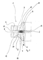
- a flange or pipe connection shown in principle in Figure 1 1 is with an inventive Force shunt seal 2 provided between a upper flange 3 or its sealing strip 4 and a lower Flange 5 or its sealing strip 6 of the flange or pipe connection is arranged in the press fit.
- the force shunt seal 2 has a hard material profile 9, which is made of stainless steel.
- the hard material profile 9 has in the upper sealing surface 10 in Figure 1, which in Pressure system on the sealing strip 4 of the upper flange 3, an upper support groove 11 and accordingly in the sealing strip 6 of the lower flange 5 associated lower sealing surface 12 a lower support groove 13.
- Both in the upper support groove 11 and in the lower Support groove 13 of the hard material profile 9 of the force shunt seal 2 is a sealing material support 14 or 15 arranged.
- the two sealing material supports are in the assembled state 14, 15 within the upper 11 and lower support groove 13 chambered, since the sealing strips 4, 6 of the flanges 3, 5 each rest on the hard material profile 9.
- the two sealing material supports 14, 15 exclusively the sealing functions of the Force shunt seal 2 meet.
- the two sealing material pads 14, 15 before Assembly of the force shunt seal according to the invention so far protrude from the upper 11 or the lower support groove 13, that after installing the flange or pipe connection 1 are maximally compressed.
- Graphite can be used as the material for the sealing material supports 14, 15 with a purity of approx. 98% and an ash content of approx. 2% and a maximum chloride content of 50 ppm, whose initial bulk density is approximately 1.0 g / cm3. It initial densities of up to 1.6 g / cm3 are also possible.
- an asbestos-free, rubber-bonded fiber composite material can be used, e.g. for aramid fiber NBR bonded Synthetic fiber NBR-bound, carbon fiber NBR-bound or can act fiber-NBR bound; also as Steel reinforcement or the like trained modifications of aramid, Synthetic, carbon or glass fibers can be used as the material.
- PTFE materials e.g. FEP, for whom Production of the sealing material pads 14, 15 for use come.
- the sealing material pads 14, 15 from a Mixture of mica-based materials can be produced a mineral content of at least 90% and a binder content of a maximum of 10%.
- the force shunt seal 2 according to the invention can, as in Figure 4 shown to be round, but there are others Circumferential shapes, e.g. Rectangle or the like, possible.
- FIG 2 is an embodiment of the invention in cross section Force shunt seal 2 before assembly the flange or pipe connection 1 shown.
- the Bottom surface of the upper support groove 11 of the hard material profile 9 has triangular projections 18, which during assembly the force shunt seal 2, as in principle in Figure 3 is shown, penetrate into the upper sealing material pad 14.
- FIGS. 2 and 3 only the upper sealing material support 14 is shown; corresponding processes also take place in context with the lower sealing material pad 15 instead, which is only shown in Figure 1.
- the upper sealant pad 14 By penetrating the triangular projections 18 in the upper sealant pad 14 becomes the upper sealant pad 14 firmly positioned within the upper support groove 11 or fixed. To avoid the triangular Projections 18 when installing the force shunt seal 2 or in the following operation the upper sealing material support 14 penetrate is the height of the triangular protrusions 18 less than the depth of the upper support groove 11.
- the cutting edges 21, 22 are also by means of triangular projections 25, 26, the cutting edges 21 and 22 respectively approximately in the plane of the sealing surfaces 10, 12 of the hard material profile 9 are arranged.
- the force shunt seal 2 according to the invention has this or whose hard material profile 9 has a centering edge 27, the Outside diameter the distance between two diametrically opposite screw openings 7 of the flange or pipe connection 1 corresponds. This is at an eccentric arrangement of the force shunt seal 2 no assembly of the flange or pipe connection 1 possible because the centering edge 27 then in some screw holes 7 minutes.
- the width of the sealing material pads 14, 15 in relation to the total width of the hard material profile 9 of the force shunt seal 2 can with comparatively large seals approx. 31.25 and approx. 30 for comparatively small seals %. This makes the use comparatively less Screw grades in the manufacture of the flange or Pipe connection 1 enables.
Landscapes
- Engineering & Computer Science (AREA)
- General Engineering & Computer Science (AREA)
- Mechanical Engineering (AREA)
- Gasket Seals (AREA)
- Flanged Joints, Insulating Joints, And Other Joints (AREA)
Applications Claiming Priority (2)
| Application Number | Priority Date | Filing Date | Title |
|---|---|---|---|
| DE19755318 | 1997-12-12 | ||
| DE1997155318 DE19755318B4 (de) | 1997-12-12 | 1997-12-12 | Kraftnebenschlußdichtung zur Abdichtung von Flansch- bzw. Rohrleitungsverbindungen |
Publications (3)
| Publication Number | Publication Date |
|---|---|
| EP0922897A2 true EP0922897A2 (fr) | 1999-06-16 |
| EP0922897A3 EP0922897A3 (fr) | 2000-08-09 |
| EP0922897B1 EP0922897B1 (fr) | 2003-05-14 |
Family
ID=7851726
Family Applications (1)
| Application Number | Title | Priority Date | Filing Date |
|---|---|---|---|
| EP19980123578 Expired - Lifetime EP0922897B1 (fr) | 1997-12-12 | 1998-12-10 | Dispositif d'étanchéité pour brides et connexions de tuyaux |
Country Status (2)
| Country | Link |
|---|---|
| EP (1) | EP0922897B1 (fr) |
| DE (2) | DE19758563A1 (fr) |
Cited By (6)
| Publication number | Priority date | Publication date | Assignee | Title |
|---|---|---|---|---|
| WO2010006561A1 (fr) | 2008-07-16 | 2010-01-21 | Mico, Spol. S.R.O. | Joint d'étanchéité combiné recouvert des deux côtés pour l'étanchéité de raccords à brides démontables |
| RU2554128C1 (ru) * | 2013-12-05 | 2015-06-27 | Общество с ограниченной ответственностью "ИЛЬМА" | Фланцевая металлическая прокладка |
| CZ306510B6 (cs) * | 2009-02-18 | 2017-02-22 | Mico, Spol. S R.O. | Plošné z vnější strany oboustranně obložené hřebenové těsnění přírubových spojů |
| RU2641987C1 (ru) * | 2016-10-03 | 2018-01-23 | Олег Юрьевич Исаев | Волновая прокладка |
| DE102018104793A1 (de) | 2018-03-02 | 2019-09-05 | Lannewehr + Thomsen Gmbh & Co. Kg | Dichtungsring zur Abdichtung von Flanschverbindungen |
| CN110792858A (zh) * | 2019-11-25 | 2020-02-14 | 苏州宝骅密封科技股份有限公司 | 一种密封装置 |
Families Citing this family (5)
| Publication number | Priority date | Publication date | Assignee | Title |
|---|---|---|---|---|
| DE102006010430A1 (de) * | 2006-03-03 | 2007-09-06 | Scholtz & Jeckel Gmbh & Co. Kg | Ringdichtung |
| DE102013003401A1 (de) | 2013-02-28 | 2014-08-28 | Klinger Ag | Flachdichtung für Flanschverbindungen |
| US10145498B2 (en) * | 2013-05-31 | 2018-12-04 | Kyowa Industry Co., Ltd. | Flange joining structure and seal body used therein |
| GB201814134D0 (en) | 2018-08-30 | 2018-10-17 | Flexitallic Invest Inc | A gasket |
| GB202003996D0 (en) | 2020-03-19 | 2020-05-06 | Flexitallic Invest Inc | A gasket |
Family Cites Families (8)
| Publication number | Priority date | Publication date | Assignee | Title |
|---|---|---|---|---|
| DE2514281A1 (de) * | 1975-04-02 | 1976-10-14 | Kempchen & Co Gmbh | Ringdichtung fuer flanschverbindungen |
| DE3320665A1 (de) * | 1983-06-08 | 1984-12-13 | Cyril Xavier Georges Saint-Cloud Latty | Dichtungsaufbau |
| DE3601773A1 (de) * | 1985-01-28 | 1986-07-31 | Fawcett Engineering Ltd., Bromborough, Wirral | Dichtung und dichtungseinrichtungen |
| DE3643283A1 (de) * | 1986-09-09 | 1988-03-17 | Ibk Wiesehahn Gmbh & Co Kg | Dichtung zum abdichten ruhender flaechen |
| DE9100438U1 (de) * | 1990-11-30 | 1991-04-04 | Jung, Alfred H., 8000 München | Dichtungsanordnung für eine Flanschverbindung |
| DE9304123U1 (de) * | 1993-03-19 | 1993-08-19 | Jung, Alfred H., 81677 München | Dichtungsanordnung für Flanschverbindung gegen äußere Einflüsse |
| DE9317130U1 (de) * | 1993-11-09 | 1994-03-17 | Jung, Alfred H., 81677 München | Zentriereinrichtung für statische Dichtungen |
| DE59610155D1 (de) * | 1995-03-15 | 2003-03-27 | Alfred H Jung | Dichtungsanordnung für eine flache flanschverbindung |
-
1997
- 1997-12-12 DE DE19758563A patent/DE19758563A1/de not_active Ceased
- 1997-12-12 DE DE1997155318 patent/DE19755318B4/de not_active Expired - Fee Related
-
1998
- 1998-12-10 EP EP19980123578 patent/EP0922897B1/fr not_active Expired - Lifetime
Cited By (9)
| Publication number | Priority date | Publication date | Assignee | Title |
|---|---|---|---|---|
| WO2010006561A1 (fr) | 2008-07-16 | 2010-01-21 | Mico, Spol. S.R.O. | Joint d'étanchéité combiné recouvert des deux côtés pour l'étanchéité de raccords à brides démontables |
| RU2482362C2 (ru) * | 2008-07-16 | 2013-05-20 | Мицо, Спол. С.Р.О. | Плоская гребенчатая уплотнительная прокладка с двусторонними накладками для герметизации разъемных фланцевых соединений |
| US8684363B2 (en) | 2008-07-16 | 2014-04-01 | Mico, Spol., S.R.O | Comby two-sided overlain gasket for sealing of dismountable flanged joints |
| CZ306510B6 (cs) * | 2009-02-18 | 2017-02-22 | Mico, Spol. S R.O. | Plošné z vnější strany oboustranně obložené hřebenové těsnění přírubových spojů |
| RU2554128C1 (ru) * | 2013-12-05 | 2015-06-27 | Общество с ограниченной ответственностью "ИЛЬМА" | Фланцевая металлическая прокладка |
| RU2641987C1 (ru) * | 2016-10-03 | 2018-01-23 | Олег Юрьевич Исаев | Волновая прокладка |
| DE102018104793A1 (de) | 2018-03-02 | 2019-09-05 | Lannewehr + Thomsen Gmbh & Co. Kg | Dichtungsring zur Abdichtung von Flanschverbindungen |
| CN110792858A (zh) * | 2019-11-25 | 2020-02-14 | 苏州宝骅密封科技股份有限公司 | 一种密封装置 |
| CN110792858B (zh) * | 2019-11-25 | 2024-05-28 | 苏州宝骅密封科技股份有限公司 | 一种密封装置 |
Also Published As
| Publication number | Publication date |
|---|---|
| DE19758563A1 (de) | 2001-09-20 |
| DE19755318B4 (de) | 2006-02-09 |
| EP0922897A3 (fr) | 2000-08-09 |
| EP0922897B1 (fr) | 2003-05-14 |
| DE19755318A1 (de) | 1999-07-01 |
Similar Documents
| Publication | Publication Date | Title |
|---|---|---|
| DE10019567A1 (de) | Dichtung | |
| DE2647235A1 (de) | Distanzhalter fuer durch schutzrohre hindurchgefuehrte rohre | |
| DE3217329A1 (de) | Zylinderkopfdichtung fuer hubkolben-brennkraftmaschinen | |
| EP0922897B1 (fr) | Dispositif d'étanchéité pour brides et connexions de tuyaux | |
| DE19608706A1 (de) | Saugverbinder für eine Pumpe | |
| DE69205061T2 (de) | Geteilte Abdichtung. | |
| DE60207595T2 (de) | Stopfbuchsendichtung und dieselbe aufweisende Dichtungsvorrichtung | |
| DE4309088A1 (de) | Ortsfest einbaubare Scheibe für Kraftfahrzeuge | |
| EP0053089A1 (fr) | Bride d'attache | |
| DE69401399T2 (de) | Rohrschelle | |
| WO2022117821A1 (fr) | Segment de piston pour compresseur à piston | |
| EP0057373A1 (fr) | Manchon de serrage pour tuyaux | |
| DE2600816A1 (de) | Verbindung | |
| EP0846906B1 (fr) | Collier de serrage plat en une pièce | |
| DE29723073U1 (de) | Dichtungsvorrichtung zum abdichtenden Durchführen mindestens einer Leitung | |
| DE8513179U1 (de) | Dichtungsanordnung | |
| DE102013015895A1 (de) | Pressfitting und Verbindungsanordnung mit einem solchen Pressfitting | |
| DE20019051U1 (de) | Glimmer für Auspuff | |
| WO2001018362A1 (fr) | Combinaison d'une unite principale et d'au moins une unite fonctionnelle surajoutee | |
| DE2630499C2 (de) | Dichtungsanordnung für einen in eine Deckelaufnahme eingesetzten Deckel | |
| DE3248072A1 (de) | Durch kaltverformung an ihren laengs- oder querraendern mit nachbarplatten verbindbare platte | |
| DE2607128C3 (de) | Elastische Profildichtung für axial schließende, symmetrische Kupplungen | |
| DE102006007270B4 (de) | Flachdichtung | |
| DE20102642U1 (de) | Abdichtsystem sowie Zentrierhilfe für einlagige Zylinderkopfdichtungen | |
| DE6610293U (de) | Dichtungsanordnung zwischen zwei koaxialen gegeneinander in axialrichtung verschiebbaren oberflaechen. |
Legal Events
| Date | Code | Title | Description |
|---|---|---|---|
| PUAI | Public reference made under article 153(3) epc to a published international application that has entered the european phase |
Free format text: ORIGINAL CODE: 0009012 |
|
| AK | Designated contracting states |
Kind code of ref document: A2 Designated state(s): BE CH FR LI LU NL |
|
| AX | Request for extension of the european patent |
Free format text: AL;LT;LV;MK;RO;SI |
|
| PUAL | Search report despatched |
Free format text: ORIGINAL CODE: 0009013 |
|
| AK | Designated contracting states |
Kind code of ref document: A3 Designated state(s): AT BE CH CY DE DK ES FI FR GB GR IE IT LI LU MC NL PT SE |
|
| AX | Request for extension of the european patent |
Free format text: AL;LT;LV;MK;RO;SI |
|
| 17P | Request for examination filed |
Effective date: 20001102 |
|
| AKX | Designation fees paid |
Free format text: BE CH FR LI LU NL |
|
| 17Q | First examination report despatched |
Effective date: 20020605 |
|
| REG | Reference to a national code |
Ref country code: DE Ref legal event code: 8566 |
|
| GRAH | Despatch of communication of intention to grant a patent |
Free format text: ORIGINAL CODE: EPIDOS IGRA |
|
| GRAH | Despatch of communication of intention to grant a patent |
Free format text: ORIGINAL CODE: EPIDOS IGRA |
|
| GRAA | (expected) grant |
Free format text: ORIGINAL CODE: 0009210 |
|
| AK | Designated contracting states |
Designated state(s): BE CH FR LI LU NL |
|
| REG | Reference to a national code |
Ref country code: CH Ref legal event code: EP |
|
| REG | Reference to a national code |
Ref country code: CH Ref legal event code: NV Representative=s name: E. BLUM & CO. PATENTANWAELTE |
|
| ET | Fr: translation filed | ||
| PLBE | No opposition filed within time limit |
Free format text: ORIGINAL CODE: 0009261 |
|
| STAA | Information on the status of an ep patent application or granted ep patent |
Free format text: STATUS: NO OPPOSITION FILED WITHIN TIME LIMIT |
|
| 26N | No opposition filed |
Effective date: 20040217 |
|
| REG | Reference to a national code |
Ref country code: CH Ref legal event code: PFA Owner name: IBK WIESEHAHN GMBH Free format text: IBK WIESEHAHN GMBH#RAIFFEISENSTRASSE 5#46244 BOTTROP (DE) -TRANSFER TO- IBK WIESEHAHN GMBH#RAIFFEISENSTRASSE 5#46244 BOTTROP (DE) |
|
| PGFP | Annual fee paid to national office [announced via postgrant information from national office to epo] |
Ref country code: NL Payment date: 20071031 Year of fee payment: 10 Ref country code: LU Payment date: 20071220 Year of fee payment: 10 |
|
| PGFP | Annual fee paid to national office [announced via postgrant information from national office to epo] |
Ref country code: CH Payment date: 20071112 Year of fee payment: 10 |
|
| PGFP | Annual fee paid to national office [announced via postgrant information from national office to epo] |
Ref country code: BE Payment date: 20071122 Year of fee payment: 10 |
|
| PGFP | Annual fee paid to national office [announced via postgrant information from national office to epo] |
Ref country code: FR Payment date: 20071017 Year of fee payment: 10 |
|
| BERE | Be: lapsed |
Owner name: *IBK WIESEHAHN G.M.B.H. Effective date: 20081231 |
|
| REG | Reference to a national code |
Ref country code: CH Ref legal event code: PL |
|
| NLV4 | Nl: lapsed or anulled due to non-payment of the annual fee |
Effective date: 20090701 |
|
| PG25 | Lapsed in a contracting state [announced via postgrant information from national office to epo] |
Ref country code: BE Free format text: LAPSE BECAUSE OF NON-PAYMENT OF DUE FEES Effective date: 20081231 |
|
| REG | Reference to a national code |
Ref country code: FR Ref legal event code: ST Effective date: 20090831 |
|
| PG25 | Lapsed in a contracting state [announced via postgrant information from national office to epo] |
Ref country code: LI Free format text: LAPSE BECAUSE OF NON-PAYMENT OF DUE FEES Effective date: 20081231 Ref country code: CH Free format text: LAPSE BECAUSE OF NON-PAYMENT OF DUE FEES Effective date: 20081231 |
|
| PG25 | Lapsed in a contracting state [announced via postgrant information from national office to epo] |
Ref country code: NL Free format text: LAPSE BECAUSE OF NON-PAYMENT OF DUE FEES Effective date: 20090701 |
|
| PG25 | Lapsed in a contracting state [announced via postgrant information from national office to epo] |
Ref country code: FR Free format text: LAPSE BECAUSE OF NON-PAYMENT OF DUE FEES Effective date: 20081231 |
|
| PG25 | Lapsed in a contracting state [announced via postgrant information from national office to epo] |
Ref country code: LU Free format text: LAPSE BECAUSE OF NON-PAYMENT OF DUE FEES Effective date: 20081210 |